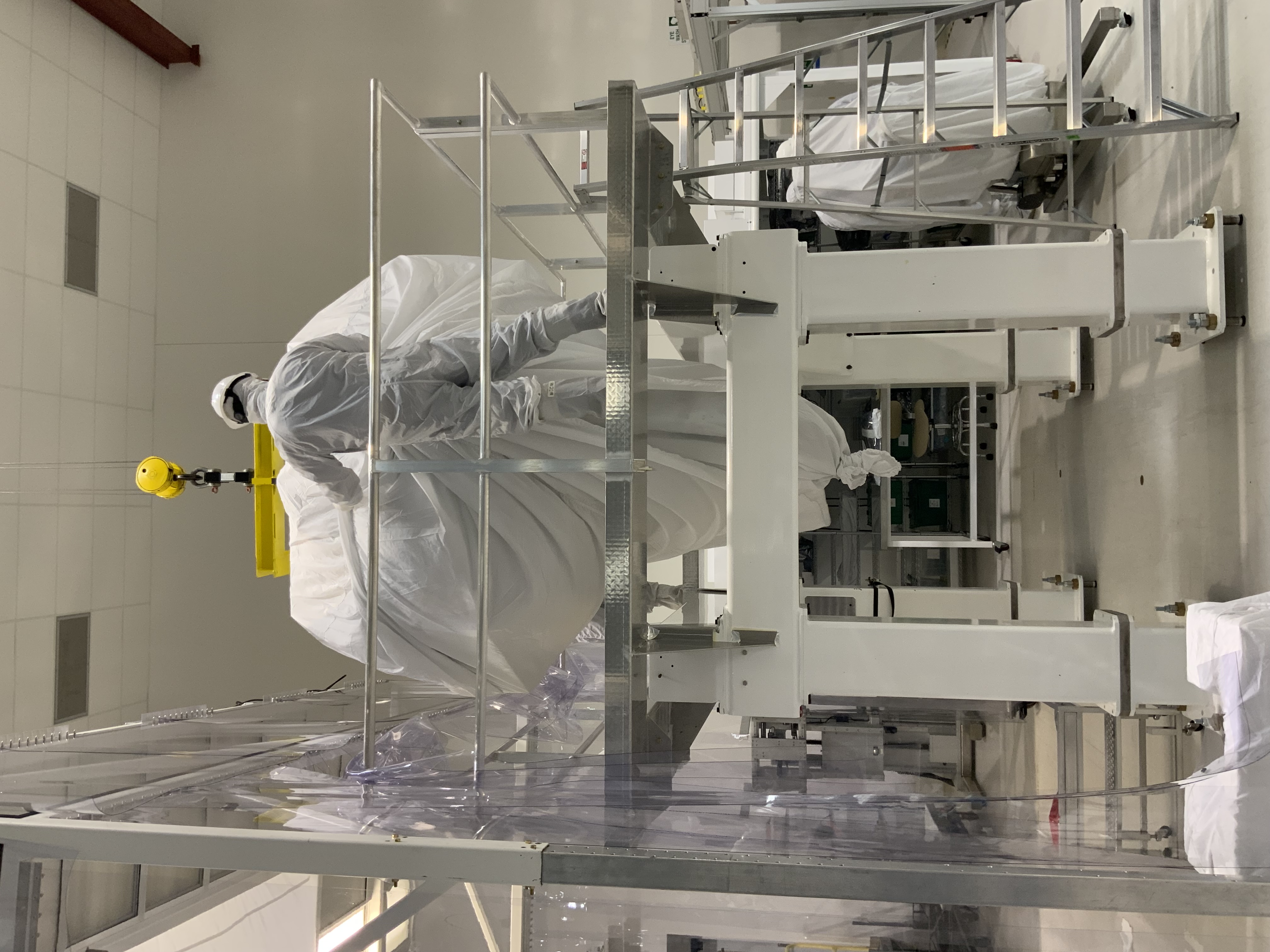
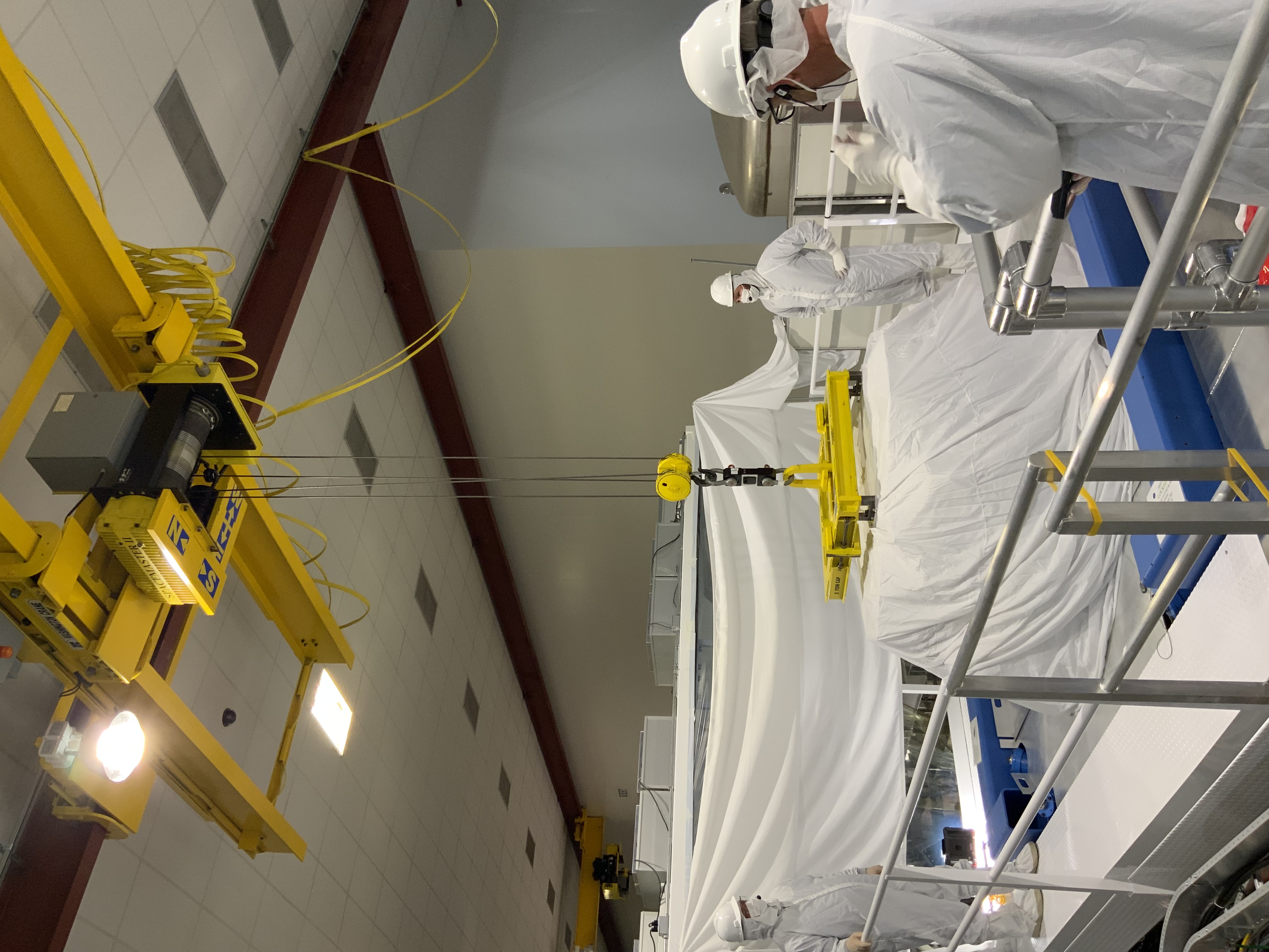
Displaying reports 761-780 of 83119.Go to page Start 35 36 37 38 39 40 41 42 43 End
Reports until 16:13, Wednesday 04 June 2025
H1 ISC
matthewrichard.todd@LIGO.ORG - posted 16:13, Wednesday 04 June 2025 (84797)
Looking at LSC-REFL_A_RIN at different thermal states

M. Todd, C. Cahillane


We are looking at the RIN in LSC-REFL_A to try and understand if there are some cavity dynamics that can give an estimate of the power recycling cavity mode-matching to the arms (for some more background, see Daniel's alog 70985)

I've made a plot that shows some interesting changes in the REFL_RIN asd as a function of thermal state. In particular I've looked at the asd at 4 different times as we thermalize after locking and stabilize the ISS.

There's some very interesting dynamics around 5-50 Hz. For the HF dynamics, I've also plotted the shot-noise limit based on that time's DC REFL_A_LF power; which I think is the limit in that frequency regime.

I've put both the dtt plot as well as my own plot that used quick_psd.


Next, I would like to model what RIN we would expect in that frequency band and compare to these measurements, specifically if this is intensity noise coupling changes due to mode mismatch changes during thermalization.

Images attached to this report
Non-image files attached to this report
H1 AOS
craig.cahillane@LIGO.ORG - posted 16:00, Wednesday 04 June 2025 - last comment - 17:39, Wednesday 04 June 2025(84796)
IM4 and MC2 TRANS now
Looking at IM4 and MC2 trans, we see that the amount of power on MC2_TRANS and IM4_TRANS has decreased by around 1%.
The plot shows a time in March 12, 2025, with white dashed lines where those values are now on June 04, 2025.
The IM4_TRANS calibration was fixed after the HAM1 work in alog 82260.

The PRG is around 3% higher now, going from 52.2 to 53.9.
The PRG calculation already incorporates this apparent 1% fall in IM4_TRANS.
Matt Todd checked the PRG at 2W in alog 84668.

As far as alignment, MC2_TRANS is servoed to zero by the input PZT using IMC ASC DOF3, so that is "unchanged".
IM4_TRANS has drifted only a small amount, from 0.1 to 0.2 in PITCH, and -0.04 to -0.10 in YAW.

This is all loosely consistent with the small changes in input pointing we've seen in the ISS array pointing seen in alog 84728.
Keita noticed that the SEG3 on the ISS QPD is totally saturated at -32768 cts due to the misalignment onto that PD, so it becomes even harder to trust the ISS QPD reference.

We have not yet closed the ISS secondloop as a part of the locking sequence, so we don't know if the beam jitter coupling to DARM problem will get worse when we close this loop.
I reckon there is a very high likelihood that it will.

Keita had more suggestions, including
1) injecting into the IMC and checking coherence between IMC WFS and the ISS array and DARM (Mr. Todd has already started this analysis alog 84775).
2) moving the input pointing into the array in PITCH and YAW and checking the PHASE between each individual array diode, maybe via line injection, to see if there is any cancellation happening, or if some diodes are more susceptible to misalignments
3) far future: change around plugs for INNER and OUTER so that the INNER diodes are the most stable, best-aligned ones.  This could improve our overall beam jitter coupling, if we think it's coupling via the intensity loop.
Images attached to this report
Non-image files attached to this report
Comments related to this report
elenna.capote@LIGO.ORG - 16:26, Wednesday 04 June 2025 (84803)

Trending back to a recent 2W lock, our PRG is a bit too high, nearing 60 when Matt has recently measured it to be 55.6. I added a gain correction factor to the PRG bank of 0.93 to account for this, in FM4. This makes our current 60 W locked PRG about 50!

craig.cahillane@LIGO.ORG - 17:39, Wednesday 04 June 2025 (84805)
I checked out the individual diodes on the array to see if they have different responses to beam jitter.
It seems like Keita's intuition was correct.

ISS array PDs 2, 3, 5, and 7 have significantly higher intensity noise at 3.5 Hz, 2.0 Hz, 1.1 Hz, and 0.15 Hz.
These frequencies correspond to some HSTS suspension resonances for YAW in particular.
Most likely is we are clipping somewhere on the path to the ISS array for only a few of these diodes.

There is also some improvement in the diode noise at around 330 Hz, 380 Hz, and 960 Hz.  

PDs 1, 4, 6, and 8 are better performing.  Out of those, we still see some beam jitter, just significantly reduced.
PDs 1, 4, 6, and 8 are better for both low and high frequency motion, which is consistent with clipping.

Jennie Wright will post a picture of the ISS array itself, but she believes the diodes are arrayed like

5 6 7 8
-   - 
1 2 3 4
  - - 
 
when looking from the back of the array where the cables are coming out.
The underlined diodes are the "bad" diodes.  
Seems to not be totally sensible as an overall DC YAW adjustment, which is consistent with our attempts to align onto this array. 

To reproduce this PSD plot, run
quick_psd H1:PSL-ISS_SECONDLOOP_PD?_OUT_DQ -t1 1433112446 -d 3600 -b 0.01 

on a CDS machine.
Non-image files attached to this comment
H1 CDS
david.barker@LIGO.ORG - posted 12:15, Wednesday 04 June 2025 (84792)
EX HWWD is showing signs of activity

WP12583

At 15:54 Tue 03jun2025 PDT the EX HWWD showed activity. This was repeated later in the day between 18:40 - 19:10. This could mean I don't need to go to EX to perform a cable-out test.

Attached 10 week trend shows when the various HWWDs went quiet and later resumed activity.

Images attached to this report
H1 CDS
david.barker@LIGO.ORG - posted 10:47, Wednesday 04 June 2025 (84791)
ISC_LOCK ADJUST_POWER state number reduced to stop false lock reporting

TJ, Dave:

The ADJUST_POWER state of the ISC_LOCK guardian node has been exercised recently during locking, with the unexpected consequence of various CDS system mis-interpreting this as entering/leaving nominal-low-noise. This is because this state's number is 1000, greater than NLN=600. For example, attachment shows CDS overview screen mistakingly showing models' SDF diffs in RED. Yesterday TJ reduced this state's number to 521, a number which wasn't available when this state was first created but has since become available (graph snippet shown).

Images attached to this report
LHO VE
david.barker@LIGO.ORG - posted 10:15, Wednesday 04 June 2025 (84790)
Wed CP1 Fill

Wed Jun 04 10:10:09 2025 INFO: Fill completed in 10min 5secs

Gerardo confirmed a good fill curbside.

Images attached to this report
LHO General
ibrahim.abouelfettouh@LIGO.ORG - posted 07:32, Wednesday 04 June 2025 - last comment - 10:11, Wednesday 04 June 2025(84786)
OPS Day Shift Start

TITLE: 06/04 Day Shift: 1430-2330 UTC (0730-1630 PST), all times posted in UTC
STATE of H1: Planned Engineering
OUTGOING OPERATOR: TJ
CURRENT ENVIRONMENT:
    SEI_ENV state: CALM
    Wind: 11mph Gusts, 6mph 3min avg
    Primary useism: 0.02 μm/s
    Secondary useism: 0.15 μm/s
QUICK SUMMARY:

IFO is in DOWN and PLANNED ENGINEERING

Plan today is to continue lock acquisition. Might attempt an initial alignment whilst the comissioners arrive.

Comments related to this report
ibrahim.abouelfettouh@LIGO.ORG - 09:08, Wednesday 04 June 2025 (84788)

HAM1 ISI WD has been tripped since yesterday morning. This seems to be related to lock stability issues in the last DAY and EVE.

camilla.compton@LIGO.ORG - 10:11, Wednesday 04 June 2025 (84789)

Sheila, Ibrahim, Julia

We lost lock after 6 minutes at LOWNOISE_ASC, this wasn't clearly a CSOFT/DSOFT ringup and appears ~equally in PIT and YAW. Adjusting DSOFT gains didn't help. We are suspicious of a 1Hz instability in DC1 centering loop, plot attached.

We initially thought the 1Hz was due to HAM1 bring tripped but it didn't completely go away in the DC1 spectrum after HAM1 untripped. See attached spectra: references are with HAM1 tripped, live traces are HAM1 damped, red trace is DC1 with large 1Hz artifact.

Images attached to this comment
H1 General
oli.patane@LIGO.ORG - posted 22:21, Tuesday 03 June 2025 (84784)
Ops Eve Shift End

TITLE: 06/04 Eve Shift: 2330-0500 UTC (1630-2200 PST), all times posted in UTC
STATE of H1: Planned Engineering
INCOMING OPERATOR: None
SHIFT SUMMARY:

Just put the detector in DOWN for the night (and for Matt's IM test tonight). Elenna and I have been unable to fully lock DRMI for the past hour:

State of today's tasks (posted in my shift start alog, here are their updates):

LOG:

22:55UTC Lockloss from LOWNOISE_LENGTH_CONTROL due to commissioner error
23:30 Lockloss from ENGAGE_DRMMI_ASC
02:37 Lockloss during LASER_NOISE_SUPPRESSION
    - ran a manual initial alignment
03:48 Lockloss from ACQUIRE_DRMI_1F due to the limit for DC6 being set to 0 and ISC_DRMI thinking that DC6 was railed (84782)
03:52 Lockloss from FIND_IR
04:00 Lockloss from ENGAGE_DRMI_ASC due to fast oscillation (same as 84769)
04:21 Lockloss from ACQUIRE_DRMI_1F due to fast oscillation (same as 84769)
04:36 Lockloss from ACQUIRE_DRMI_1F
04:43 Lockloss from ACQUIRE_DRMI_1F

H1 ISC
elenna.capote@LIGO.ORG - posted 21:02, Tuesday 03 June 2025 (84782)
False WFS DC railed Warning

Oli, Elenna

Oli and I were just baffled as we were stuck in the DRMI acquisition with ISC_DRMI throwing a warning that "WFS DC centering railed", but of course, nothing looked railed at all. We eventually lost lock just sitting there.

I found that ISC_DRMI runs:

DRMI_WFS_CENTERING = ISC_GEN_STATES.gen_WFS_DC_CENTERING('DRMI','REFL_AS_POP')
which checks
WFS_DC_centering_servos_OK(port)
and the check is:
for py in ['P', 'Y']:
for servo in servos:
if (abs(ezca['ASC-DC%s_%s_OUTPUT' % (servo, py)]) >= ezca['ASC-DC%s_%s_LIMIT' % (servo, py)]):
okayFlag = False
but then I checked DC6 and the limit is zero, so of course this function will report that the centering is railed even when it is not. It appears that the DC 1 and 2 centering loops have limits of 555, and since PM1 the same suspension type as the RMs, I have updated DC6 to have these same limits.
Images attached to this report
H1 SQZ
victoriaa.xu@LIGO.ORG - posted 20:01, Tuesday 03 June 2025 (84780)
Recovered FDS ~4.5dB in first pass almost totally automated after re-aligning FC

Kevin, Vicky

FDS basically recovered on its own with just selected "FREQ_DEP_SQZ", all we had to really do was align FC1/2 to get the filter cavity IR lock to work. Squeezer ASCs could basically walk alignment back on its own, last screenshot.

We manually turned SQZ IFO AS42 ASC on and stepped up the gain to converge it, adjusted squeezing angle, and FIS realigned itself. We then went to NO SQUEEZING and reset the AS42 "no sqz" offsets; see the offset script and accepted in SDF. For FDS, we had to manually align the filter cavity in order to transition to the IR lock because the FC REFL beam had kinda fallen off the FC WFS, so the handoff wasn't working at first. We realigned with the filter cavity locked in green, and walking FC1/2 (mostly in pitch) to maximize the FC green trans signal. This also walked the beam back onto the FC REFL WFS. Then we brought it back to FDS and manually turned on SQZ ASC gain, then turned on the FC ASC gain, and it all "just worked" getting up to about 4.5 dB.

Resolved our SDFs, and we turned the SQZ + FC ASC flags back to "True" in the guardian. Other settings were left as they were after O4b: FC beam spot control False, OPO_TRANS 95uW, and SQZ ANGLE ADF servo False/DOWN.

Note: running SQZ ASC means the homodyne now needs to be re-aligned, or else we need to set the optics (FC1 + ZMs) back to the homodyne settings (could use the "SET ZM HD" button if/after we offload asc to sliders).

Images attached to this report
H1 ISC
elenna.capote@LIGO.ORG - posted 19:42, Tuesday 03 June 2025 (84779)
Lockloss at Laser Noise Suppression- REFL B bad?

Oli, Elenna

We tried running Laser Noise Suppression, with the risk being that REFL B settings may not be right for the CARM control. Indeed, Oli and I watched the guardian log and it appears that the lockloss was exactly concurrent with the ramping on of REFL B as a second CARM sensor.

Georgia has previously checked the phasing, so I am not certain what the issue could be. If we get a chance to go through this state again tonight, I'll try stepping through everything but the CARM sensor change to confirm that is the issue.

H1 ISC
elenna.capote@LIGO.ORG - posted 19:34, Tuesday 03 June 2025 - last comment - 13:51, Thursday 05 June 2025(84778)
ASC Problems may be related to bad DC centering loops

Oli, Georgia, Elenna

While we were taking care of several LSC items, Georgia pointed out that we are seeing the 0.8 Hz buzzing in INP1 yaw again, and to a lesser degree CHARD Y. While we did several useless things to debug, I noticed that the DC centering loops were also buzzing with the same frequency oscillation. I decided to try changing the DC centering loop gain (since I had raised the loop gain significantly last week), and noticed that NONE of the DC6 pitch or yaw filters were engaged, but a gain of 1 was engaged, essentially feeding the input signal right back to PM1. Bad!!

Searchingh DC6 in the guardian shows that in PREP_ASC_FOR_FULL_IFO, I found these lines of code:

ezca.get_LIGOFilter('ASC-DC6_P').only_on('INPUT','OUTPUT','DECIMATION')
ezca.get_LIGOFilter('ASC-DC6_Y').only_on('INPUT','OUTPUT','DECIMATION')

Not good! Since the gain of DC6 is set on, this effectively keeps the gain on but turns off all the filters and just feeds back the pure error signal to the suspension.

I commented those lines out of the guardian and loaded, and then reengaged all the proper filters. A large 28 Hz line that had been present in DARM disappeared at this point, likely because the DC centering loops require a 28 Hz notch to avoid some suspension mode.

After this, I then tried turning down the DC1 and DC2 pitch and yaw gains to -1. This seemed to help the buzzing in CHARD and INP1. Georgia and I were able to engage all the low noise ASC settings without any issues (CHARD P had been held in high bandwidth to avoid a ring up and the soft loops had high gain for the same reason).

We need to monitor for a while longer and also try relocking, but these changes may fix many of our ASC issues.

I have SDFed these gain changes.

Comments related to this report
georgia.mansell@LIGO.ORG - 23:30, Tuesday 03 June 2025 (84785)

While locking this arvo, we stepped through lownoise_asc slowly by hand trying to catch which step was causing the 1Hz ring up that caused locklosses yesterday.

One time we reduced the DSOFT_Y gain down, thought we saw something ring up, but when we gradually decreased it the ring up did not come back.

The CHARD_P filter and gain changes in this state seemed to cause some oscillations in the PRG, so we left CHARD_P in a high noise state for a while. This left a lot of noise in DARM (first screenshot). We later ran the lownoise_asc steps for CHARD_P, after Craig and pals phased the LSC-POP diode, and this seemed to fine (second screenshot).

Hopefully the reduced gain in DC1 and 2 and the existance of filters in the DC6 loops will improve the ASC. But if we still see ringups in lownoise_asc the next best thing to try is undoing the steps for CHARD_P.

Images attached to this comment
elenna.capote@LIGO.ORG - 13:27, Wednesday 04 June 2025 (84793)

We now have confirmation that the DC centering loops have been having a significant effect on the ASC and causing many of our problems.

The DC loops appeared to have a large amount of gain peaking at low power around 0.8 Hz (I turned up the gain too high and didn't check the gain peaking). After we powered up I measured CHARD Y, which is a loop whose gain we have not been able to raise until reaching high power during the past few days. Attached is a comparison of the CHARD Y OLG both with the DC centering loop gain high and low (cut by half).

We were able to turn up and turn down the DC centering gain to confirm that it is causing the right half plane zero in CHARD Y. We only measured CHARD Y so we don't know the effect on other loops, but it appears that other loops are also more stable with less gain in the DC centering.

Images attached to this comment
elenna.capote@LIGO.ORG - 13:51, Thursday 05 June 2025 (84822)

I have turned up the CHARD Y gain at engage ASC with no problems, this is now saved in the guardian.

H1 ISC (ISC)
craig.cahillane@LIGO.ORG - posted 19:10, Tuesday 03 June 2025 - last comment - 20:48, Tuesday 03 June 2025(84776)
LSC sensing matrix - June 03, 2025
I initially tried rephasing POP 9 by hand, but moving the POP A phase by 5 degrees while we're locked using it was way too much and immediately caused a lockloss.
The next lock, we found Gabriele's old LSC sensing matrix measuring software in 
/ligo/gitcommon/labutils/lsc_sensing_matrix/lsc_sensing_matrix.py
It works great still.
The 250 Hz line is injected using awg, and the FM5 EBS250 notch filters are still in the right location. 
The excitation amplitudes were 10x too strong, so we lowered them and it stopped the saturations.

The resulting phases found initially are posted as the first PDF.
We were pretty far off in POP 9, by 20 degrees, and by -11 degrees in POP 45.

To rephase, I wrote the script to rotate the phase of POP very slowly while in lock:

step_size = 11
steps = 100000
total_time = 110
init_value = ezca["LSC-POP_A_RF45_PHASE_R"]
for ii in range(1,steps):
    small_step_size = step_size * ii / steps
    small_time = total_time / steps
    print(f"{ii}: {small_step_size}")
    time.sleep(small_time)
    ezca["LSC-POP_A_RF45_PHASE_R"] = init_value + small_step_size

This one worked, with only very small glitches visible in DARM.
PDF 2 shows the resulting fixed LSC matrix measurement, at 60 W input power.

Next, we adjusted the LSC sensing matrix according to Jenne's old instructions: alog 68547.
We turned on SRCL2 and MICH2 FM5 EBS250 notch filters, and started a 250 Hz line in PRCL again.

We then plotted SRCL1 and PRCL1 error signals while adjusting the POP 9 I -> SRCL intrix value by 0.005 steps, looking to minimize the appearance of the 250 Hz PRCL line sensed in SRCL.
We didn't move LSC-PD_DOF_MTRX_SETTING_5_1 much: only by 0.02 from 0.10408 to 0.085, but got significant improvement, maybe a factor of 3 better.
Makes some sense we'd have to adjust this after rephasing the POP diodes.
The resulting LSC sensing matrix is posted as the PNG.
Images attached to this report
Non-image files attached to this report
Comments related to this report
elenna.capote@LIGO.ORG - 20:48, Tuesday 03 June 2025 (84781)

These were not SDFed but I trended and figured out what the new values are. Screenshot attached.

Images attached to this comment
H1 GRD
georgia.mansell@LIGO.ORG - posted 18:19, Tuesday 03 June 2025 - last comment - 18:41, Tuesday 03 June 2025(84774)
Low key guardian changes today

ISC_LOCK LOWNOISE_ASC

ISC_DRMI

CAMERA_SERVO


Comments related to this report
oli.patane@LIGO.ORG - 18:41, Tuesday 03 June 2025 (84777)

WRT the ISC_DRMI guardian changes, I also implemented the use_DRMI_ASC dictionary into DRMI_LOCKED_CHECK_ASC and OFFLOAD_DRMI_ASC in ISC_LOCK.

Now if we ever need to turn the convergence checker loops off for only some loops, we'll only need to edit lscparams instead of multiple different states inside two different guardians.

H1 ISC
elenna.capote@LIGO.ORG - posted 17:00, Tuesday 03 June 2025 - last comment - 21:12, Tuesday 03 June 2025(84769)
Strange Oscillation during DRMI ASC

Elenna, Georgia, Craig, Stefan, Oli

We saw a very strange oscillation that appears to be beamsplitter related during the engagement of DRMI ASC. I tried turning down various DRMI ASC gains: SRC1, SRC2, MICH P, and it made no difference. We were getting BS saturation warnings. Finally, I just moved from"engage drmi asc" to "turn on BS stage 2" and the oscillations appeared to reduced. We saw large peaks with harmonics in the corner LSC signals starting near 18 Hz. We are wondering if it's an errant beamsplitter bounce mode?

Comments related to this report
craig.cahillane@LIGO.ORG - 17:24, Tuesday 03 June 2025 (84770)
Seems to be the SRCL1 offset change from 800 cts to zero counts.
The ringup frequency is 16.2 Hz and is seen in every loop very strongly, especially MICH.  

I thought the MICH2 BR0604 filters might have something to do with this, but those are focused more along 17.8 Hz.

Elenna points out that the 16.2 Hz ringing is present in all LSC prior to to the SRLC1 offset change.  
It is clear that the SRCL1 offset change makes things 100 times worse over a period of around 5 seconds.

We could consider slowing down the offset change, as it currently happens in only one second.  
We could also investigate these bounce roll notches to ensure they are at the correct frequency for the BS.
We could check the DRMI LSC OLGs at acquisition as well, as one may be on the edge of stability during a messy acquisition.
Images attached to this comment
elenna.capote@LIGO.ORG - 21:12, Tuesday 03 June 2025 (84783)

This has caused another DRMI lockloss but it was too fast to determine where it was coming from.

We haven't been able to lock DRMI since this particular lockloss, so we haven't had a chance to measure OLGs to see if it's a loop instability.

H1 SQZ (CDS, ISC)
victoriaa.xu@LIGO.ORG - posted 13:28, Tuesday 03 June 2025 - last comment - 18:59, Friday 06 June 2025(84755)
Model changes for faster ADF demodulation in the 64kHz OMC-PI model ready to go (h1ioplsc0, h1omcpi)

Daniel, Kevin, (Erik, Dave), Vicky

Kevin is interested in taking ADF sweeps around the second higher order mode arm resonance near 10.4 kHz.

We (Daniel) made model changes in h1ioplsc0 and h1omcpi that should enable higher freq ADF demods. Daniel built the models successfully. Then Dave also built these models successfully for the custom RCG running on h1omcpi for the variable duotone. We put in a WP to boot in these changes to h1ioplsc0 and h1omcpi next Tuesday 6/10.

From h1ioplsc0, we added 2 new PCIe channels to write the digital ADF LO oscillator out to PCIe. These are H1:IOP-PCI_ADF_VCXO_{COS,SIN} in screenshot 1. We also changed a rogue limiter such that the ADF should be able to scan +/-1 MHz according to the PLL.

In h1omcpi, we use the fast 64 kHz OMC PI user model to do a fast digital demodulation of the OMC_DCPD_SUM signal using the above ADF-LO PCIe channels. This is beating the fast dcpd output signal (H1:OMC-PI_DCPD_64KHZ_AHF), against the ADF LO's cosine and sine components from PCIe (H1:IOP-PCI_ADF_VCXO_{COS,SIN}), to get the demodulated ADF I/Q signals. The demod signals will have names like H1:OMC-PI_ADF_DEMOD_{I,Q}. Screenshots 2-4.

Operationally nothing should change for the ADF or for OMC-based fast PI damping. We are just using PCI to send 2 IPC channels from an IOP model to a user model on a different computer at ~65kHz, and doing the demod in a 64kHz user model (but the demod does not go anywhere, it is just used for squeezer diagnostics).

Images attached to this report
Comments related to this report
david.barker@LIGO.ORG - 07:39, Wednesday 04 June 2025 (84787)

Model change summary:

h1ioplsc0

+2 IPC senders to H1.ipc

+2 slow channels to DAQ

h1omcpi

(+2 IPC receivers)

+33 slow channels to DAQ

victoriaa.xu@LIGO.ORG - 18:59, Friday 06 June 2025 (84881)

Model changes today seem relatively successful. No way to verify in hardware (yet), but the ADF PLL claims it successfully locks at -11kHz from carrier, so at least the limiter fix in h1ioplsc0 seems to work; in principle the ADF sweep limiter is now set at +/- 1 MHz.

I added a quick ADF demod of the 64kHz OMC DCPD SUM channel into the normal ADF screen, screenshot attached, see the very bottom. New filter banks initialized with values and filters as in the other adf demod chains. Also tried to clean it up in SDF: channels are initialized, gains and phase are monitored, and saved into sdf (h1omcpi model).

Images attached to this comment
Displaying reports 761-780 of 83119.Go to page Start 35 36 37 38 39 40 41 42 43 End