We could not retreive data for the transfer functions that ran overnight on ITMX.
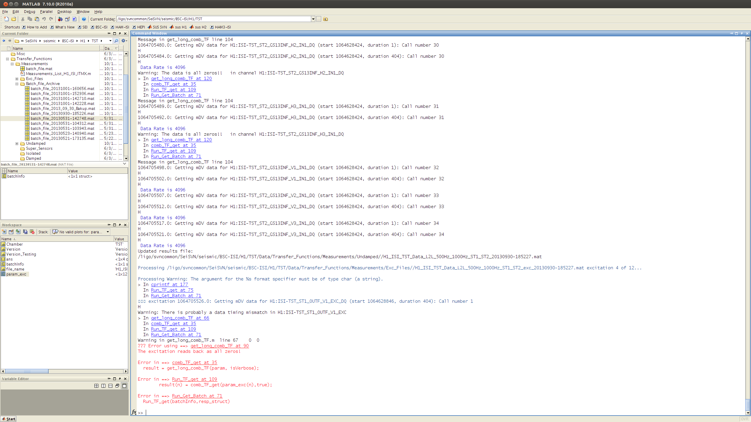
Run_Get_Batch.m, the generic script that the seismic team uses to get data from the frames, would systematically crash when collecting data for Stage1-V1 excitation, in the 500Hz-1000Hz frequency range (see attachement #1). It would also crash when trying to collect data for the other frequency bins.
We looked at the data stored in the frames (DaveB, and ArnaudP helped), and compared it with what was in the slow channels.
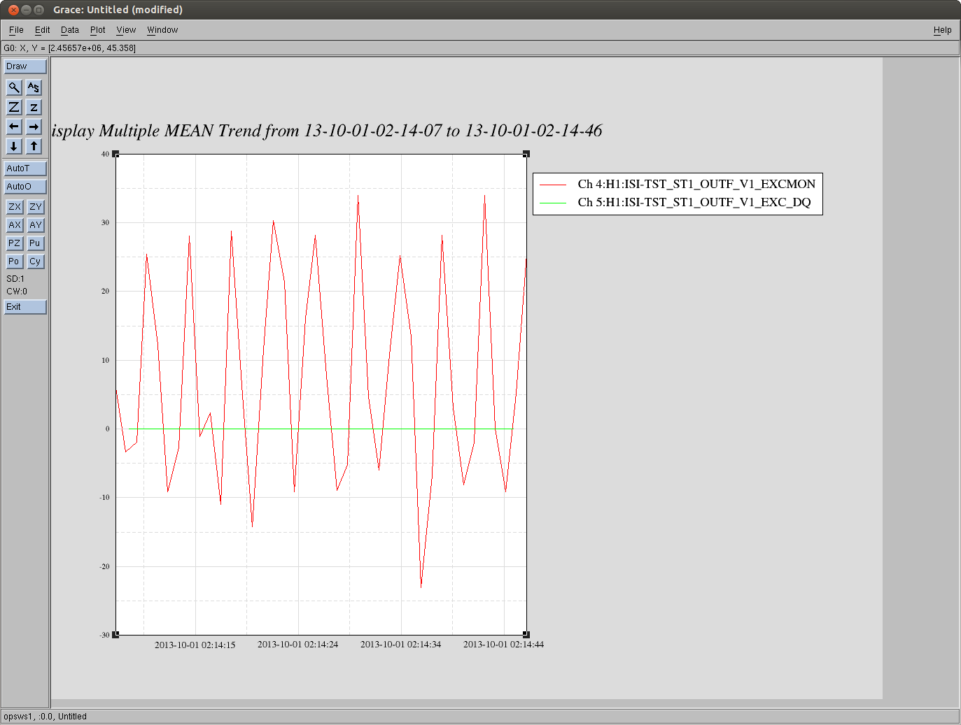
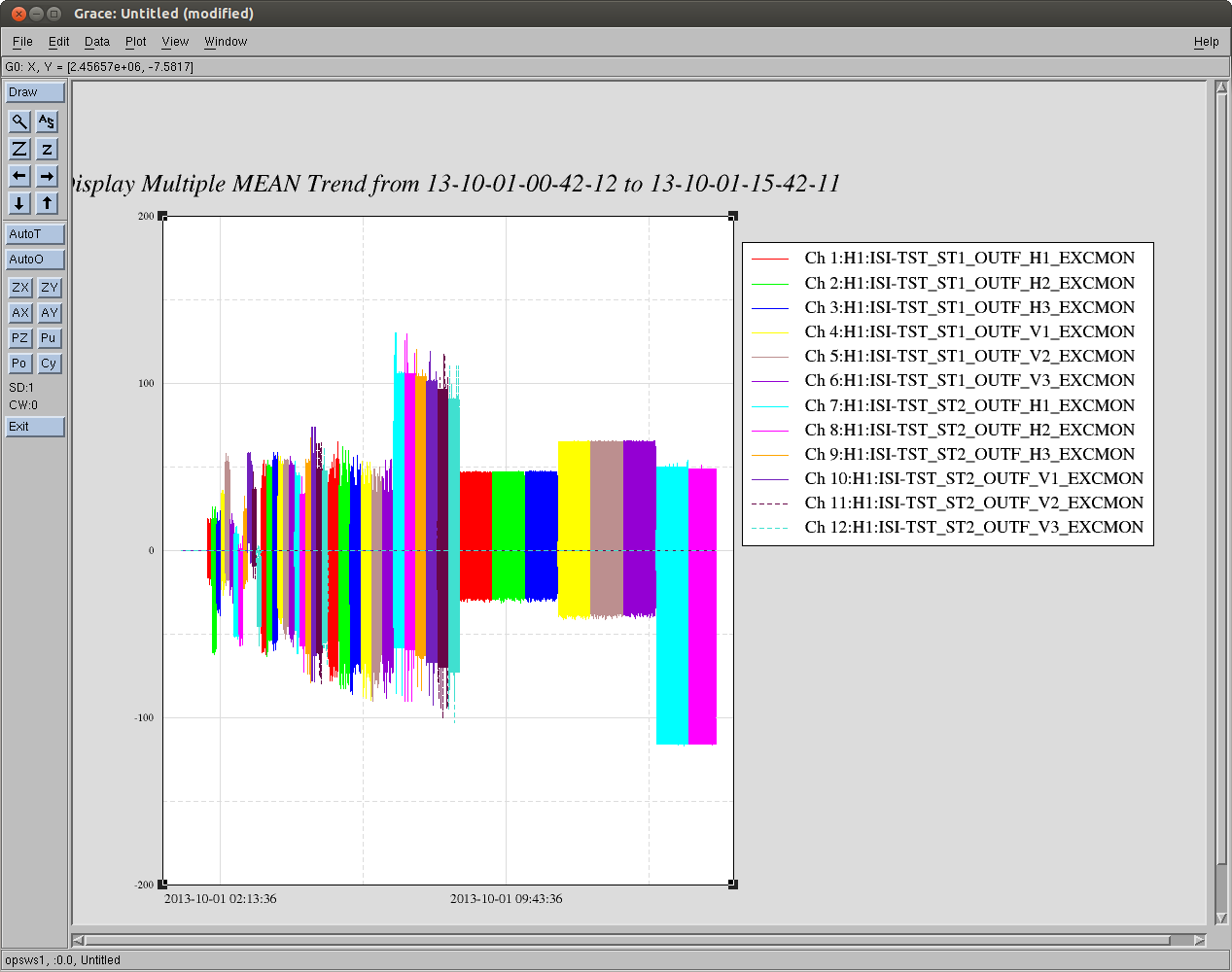
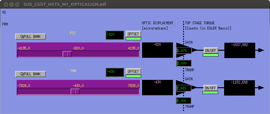
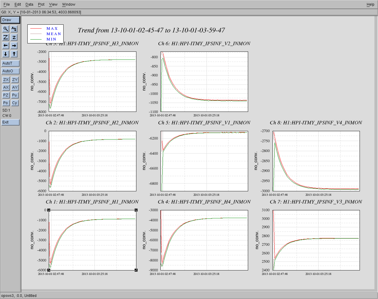
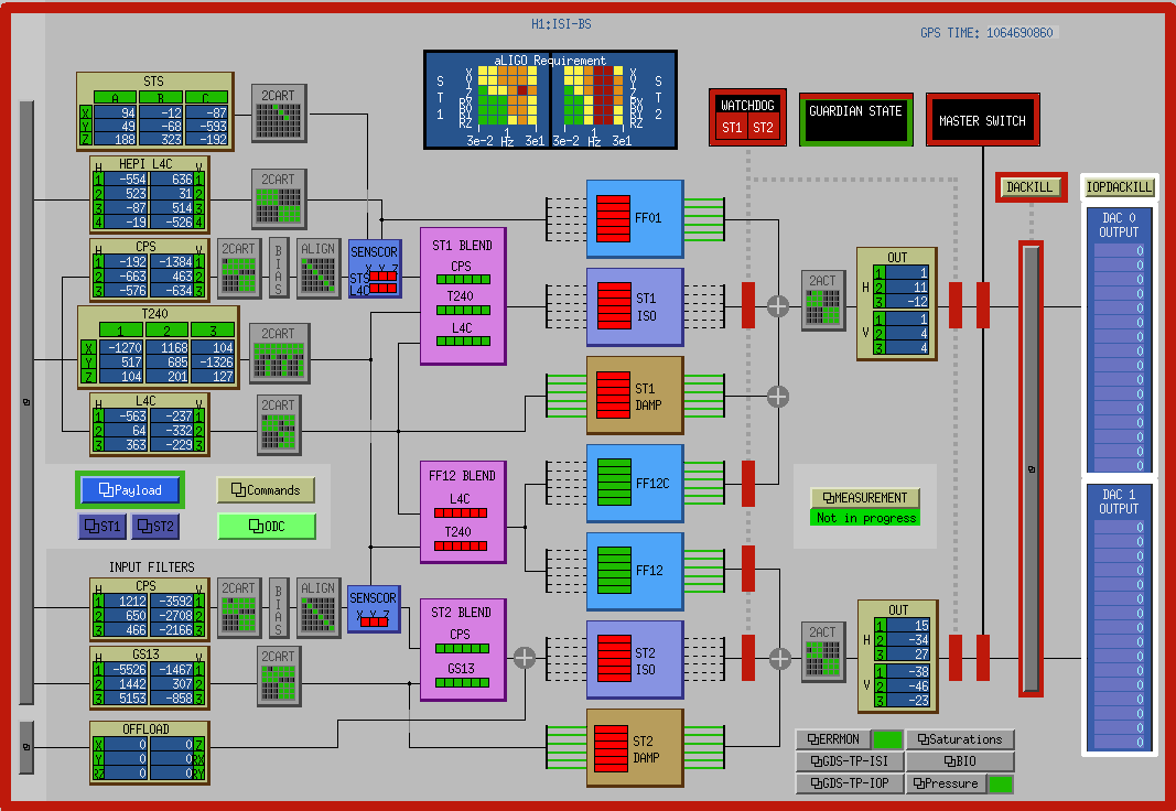
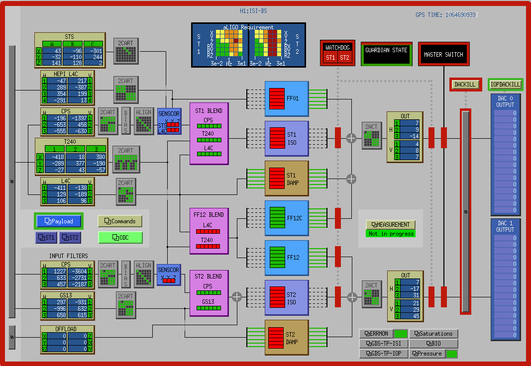
- The actuation signals were sent to the correct channels and witnessed by the related slow channels (see attahchement #2)
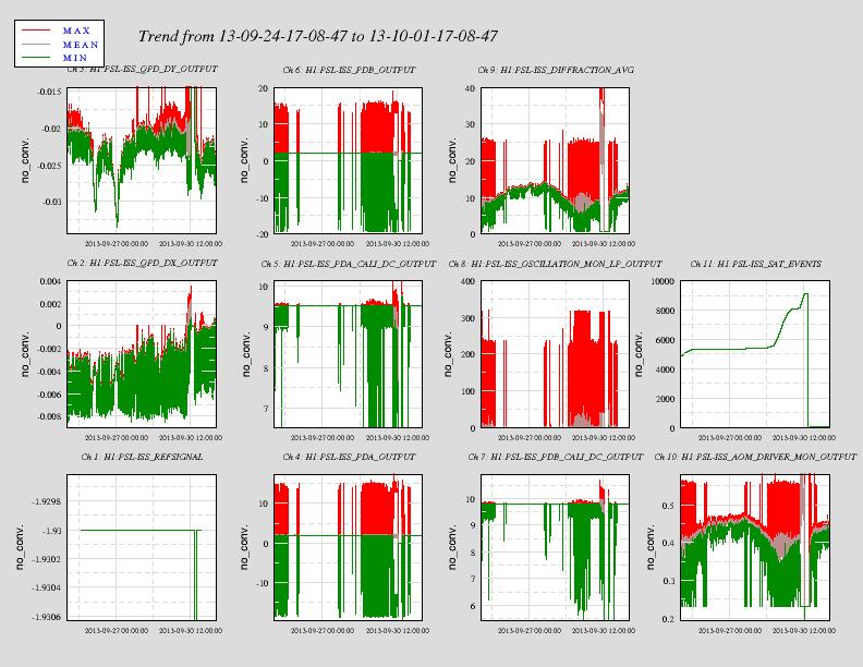
- However, the daq channel for the excitation along Stage1-V1 does not recall any excitation (see attachement #3), while one was recorded by its slow channel twin (see preious comment).
New channels were added to the master model, and h1isitst.mdl was not restarted since. When JimW and I restarted the TST model yesterday night, those channels were added to the .ini file. JimW and I did not dare restarting the DAQ without CDS people around. This is likely to be the reason why the data in the frame was corrupted.
A couple DAQ restarts were performed as part of the maintenance day today. Last one was around 3pm. We then started to run a quick set of high frequency transfer functions, and made sure that the data collection process went well. It did.
Transfer functions will be running ovenight on ITMX (currently on the test stand, using TST model)


