Dave, Hugo,
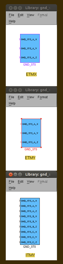
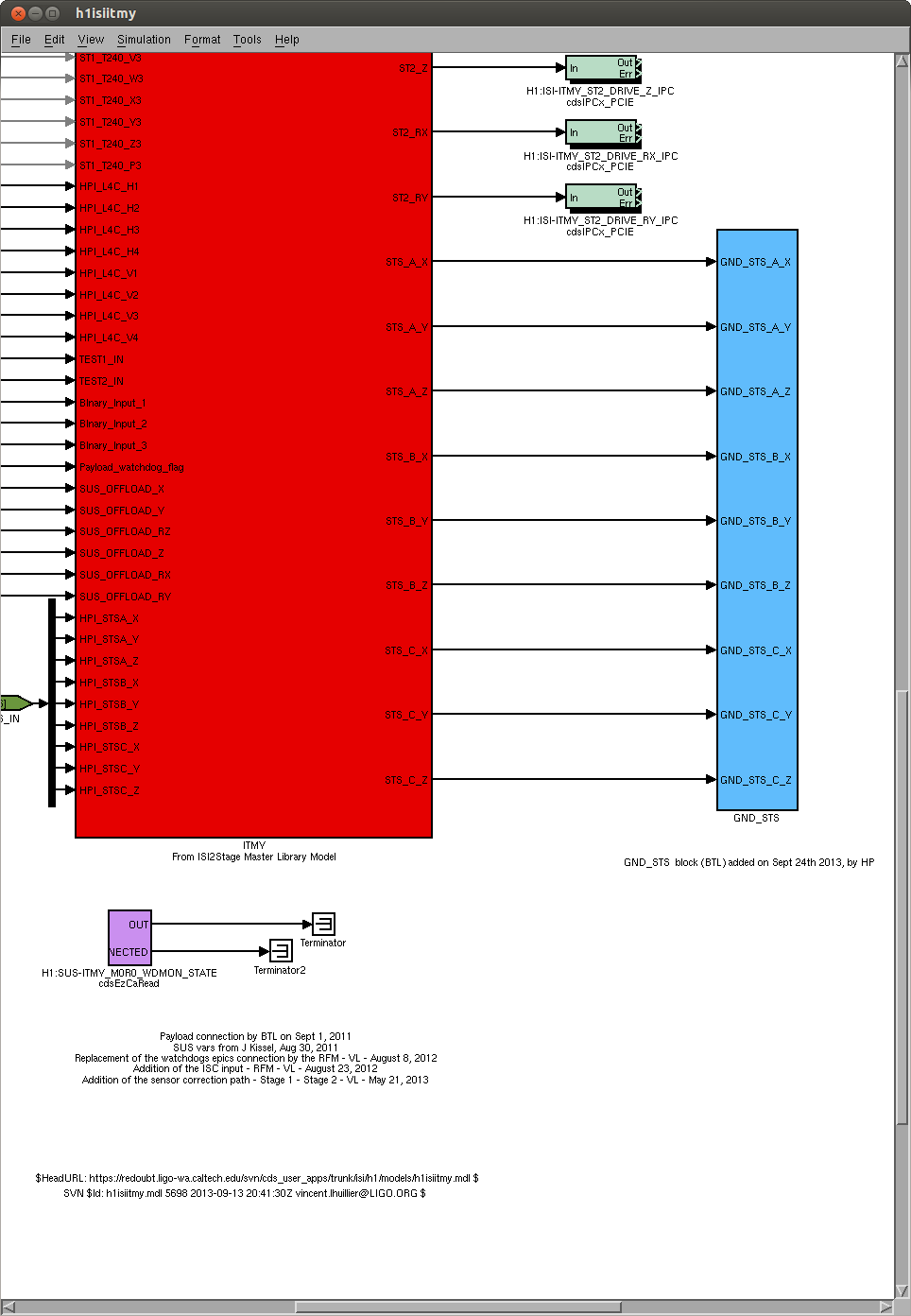
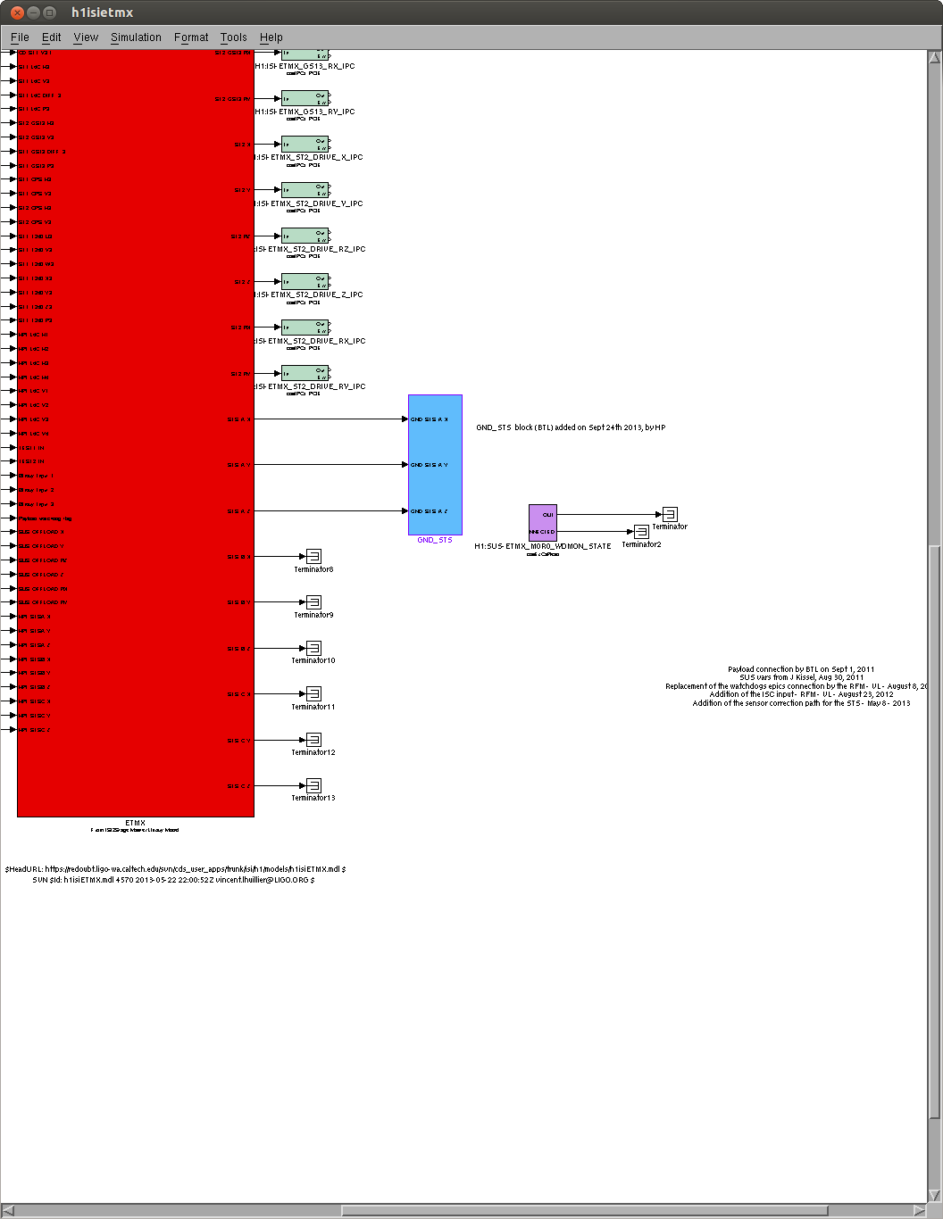
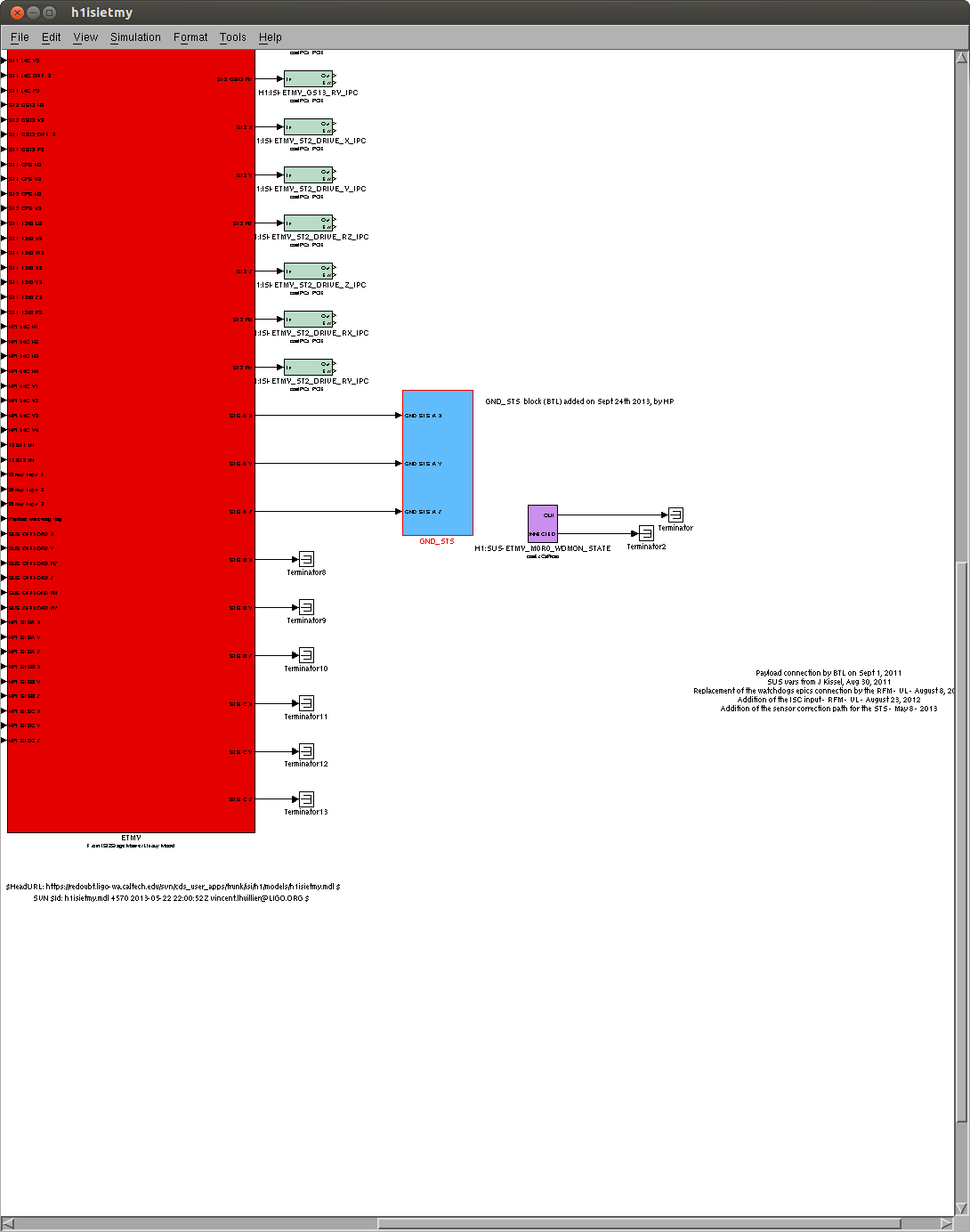
New channels were added to the science frame yesterday (LHO aLog #7849). Those channels are defined in a simmulink block called GND_STS. The GND_STS block was copied from gnd_sts_library.mdl and pasted in the BSC-ISI top level models of ITMY, ETMY, and ETMX, as intended. The gnd_sts_library.mdl contained one GND_STS block for ITMY, one for ETMX, and one for ETMY. Those three blocks carried the same name, with different content. Yesterday's work indicated that the RCG got confused by the multiplicity of names, and picked the wrong GND_STS block from the library, to generate the .ini file, which lists the channels to be recorded in the science frame.
Yesterday's solution was to rename each of these GND_STS block, within gnd-sts_library.mdl, so they would have distinct names. Doing so, impacted the names of the channes saved in the science frame:
GND_STS blocks were renamed as follow:
- GND_STS_IY, for the one to be pasted in h1isiitmy.mdl
- GND_STS_EX, for the one to be pasted in h1isietmx.mdl
- GND_STS_EY, for the one to be pasted in h1isietmy.mdl
GND_STS channels in the Science Frame were then (in red, the diffence whith what was intended by T1300742):
name: H1:ISI-GND_STS_HAM2_X_MON
name: H1:ISI-GND_STS_HAM2_X_MON
name: H1:ISI-GND_STS_HAM2_Y_MON
name: H1:ISI-GND_STS_HAM2_Y_MON
name: H1:ISI-GND_STS_HAM2_Z_MON
name: H1:ISI-GND_STS_HAM2_Z_MON
name: H1:ISI-GND_STS_HAM5_X_MON
name: H1:ISI-GND_STS_HAM5_X_MON
name: H1:ISI-GND_STS_HAM5_Y_MON
name: H1:ISI-GND_STS_HAM5_Y_MON
name: H1:ISI-GND_STS_HAM5_Z_MON
name: H1:ISI-GND_STS_HAM5_Z_MON
name: H1:ISI-GND_STS_ITMY_X_MON
name: H1:ISI-GND_STS_ITMY_X_MON
name: H1:ISI-GND_STS_ITMY_Y_MON
name: H1:ISI-GND_STS_ITMY_Y_MON
name: H1:ISI-GND_STS_ITMY_Z_MON
name: H1:ISI-GND_STS_ITMY_Z_MON
name: H1:ISI-GND_STS_IY_HAM2_X_MON
name: H1:ISI-GND_STS_IY_HAM2_Y_MON
name: H1:ISI-GND_STS_IY_HAM2_Z_MON
name: H1:ISI-GND_STS_IY_HAM5_X_MON
name: H1:ISI-GND_STS_IY_HAM5_Y_MON
name: H1:ISI-GND_STS_IY_HAM5_Z_MON
name: H1:ISI-GND_STS_IY_ITMY_X_MON
name: H1:ISI-GND_STS_IY_ITMY_Y_MON
name: H1:ISI-GND_STS_IY_ITMY_Z_MON
name: H1:ISI-GND_STS_EX_ETMX_X_MON
name: H1:ISI-GND_STS_EX_ETMX_Y_MON
name: H1:ISI-GND_STS_EX_ETMX_Z_MON
name: H1:ISI-GND_STS_ETMY_X_MON
name: H1:ISI-GND_STS_ETMY_X_MON
name: H1:ISI-GND_STS_ETMY_Y_MON
name: H1:ISI-GND_STS_ETMY_Y_MON
name: H1:ISI-GND_STS_ETMY_Z_MON
name: H1:ISI-GND_STS_ETMY_Z_MON
name: H1:ISI-GND_STS_EY_ETMY_X_MON
name: H1:ISI-GND_STS_EY_ETMY_Y_MON
name: H1:ISI-GND_STS_EY_ETMY_Z_MON
We found a workaround this morning, so the ground STS channels would be named correctly in the science frame:
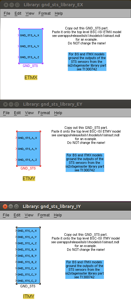
- We split gnd_sts_library.mdl into 3 distinct libraries:
- gnd_sts_library_IY.mdl (which contains the GND_STS block for ITMY)
- gnd_sts_library_EX.mdl (which contains the GND_STS block for ETMX)
- gnd_sts_library_EY.mdl (which contains the GND_STS block for ETMY)
- The GND_STS blocks were copied, and connected, into the relevant models ( h1isiitmy.mdl, h1isietmx.mdl, h1isietmy.mdl)
- We checked that the GND_STS blocks we pasted were linked to the correct simmulink libraties (gnd_sts_library_IY.mdl, gnd_sts_library_EX. mdl,gnd_sts_library_EY.mdl)
- BSC-ISI models were recompiled for ITMY, ETMX and ETMY.
- GND channel names were checked in the science frame. They are now correct (see below)
name: H1:ISI-GND_STS_HAM2_X_MON
name: H1:ISI-GND_STS_HAM2_Y_MON
name: H1:ISI-GND_STS_HAM2_Z_MON
name: H1:ISI-GND_STS_HAM5_X_MON
name: H1:ISI-GND_STS_HAM5_Y_MON
name: H1:ISI-GND_STS_HAM5_Z_MON
name: H1:ISI-GND_STS_ITMY_X_MON
name: H1:ISI-GND_STS_ITMY_Y_MON
name: H1:ISI-GND_STS_ITMY_Z_MON
name: H1:ISI-GND_STS_ETMX_X_MON
name: H1:ISI-GND_STS_ETMX_Y_MON
name: H1:ISI-GND_STS_ETMX_Z_MON
name: H1:ISI-GND_STS_ETMY_X_MON
name: H1:ISI-GND_STS_ETMY_Y_MON
name: H1:ISI-GND_STS_ETMY_Z_MON
Bottom line:
1. One should not expect RCG to pick the right simuling block, if this block has clones (same name) within the library it comes from.
2. The Seismic GND_STS (Ground streckeisen seimometers) channels are now recorded with the correct name in the science frame.


This measurement is now archived in DCC:
https://dcc.ligo.org/LIGO-E040512.