kyle.ryan@LIGO.ORG - posted 15:58, Friday 20 September 2013 (7821)
Replaced BSC2's annulus ion pump
Utilized snorkel Genie lift and Main Crane
Utilized snorkel Genie lift and Main Crane
I've made some changes to the CDS wireless access points, they will now only allow a certain list of known CDS computers to connect (this is in addition to the authentication already in place). If you come across a *CDS* computer that is not working and you think it should be, let me know. In addition, 802.11n data rates are enabled on all of the access points now that all the old OS X installs that caused issues with these data rates have been removed. This should make things a little faster for wireless clients on the network.
Yesterday I was asked by Keita to measure the reflectivity of a beam splitter which will be installed in HAM1 next week. This is called M14 in D1000313. I measured it at the OSB optics lab.
According to my measurement :
R = 99.4 +/- 0.1 % for S-polarizing beam at 1064 nm 45 deg.
R = 94.8 +/- 0.9 % for P-polarizing beam at 1064 nm 45 deg.
After some communication with Cheryl, I put away the items left in the staging area of the small cleanroom by HAM1 so that Apollo could move it for next week's entry. There were four bins of items. Cheryl and I will sort through it next week.
The installer came to finish the trim today. He was able to finish the side trim. Unfortunately, he did not bring the trim needed for the end so he'll be back one more time...
Attached are plots of dust counts requested from 4 PM September 18 to 4 PM September 19.

Pablo says the spike in counts at dust monitor 8 may be due to the removal of the clean room from over it. This would have been the small clean room between HAM2 and HAM3. I have not been out to check if that is the case.
Still investigating on tilt correction.
I started a measurement for the night. Should be done by tomorrow morning.
*** HPI ***
Undamped
*** ISI ***
750mHz blend on all the DOFs (ST1 & ST2)
Control lvl1 engaged
*** SUS ***
Damped
Jim, Sebastien
We made good progress on the ISI-ETMX testing today. All the sensors have been tested and react properly. Actuator side, we noticed an unwanted ouput voltage coming out of the corner 3 coil driver. We should be able to fix this issue with Richard tomorrow. Except corner 3, all the actuators behave properly.
I've started a set of L2L measurements for corner 1 and 2 tonight. If everything goes well, I'll complete this set tomorrow night.
Tonight measurement should be done by 6am tomorrow morning.
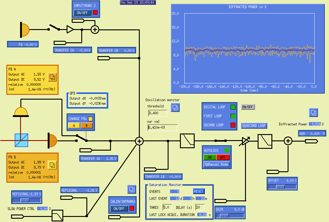
RickS and DougC

After prompting from ChristinaB during this morning's PSL group telecon, we enabled the ISS loop which has been switched off for the past week or two, reportedly due to instability operating it with the FSS loop.

We first adjusted the refsignal from -1.98 to -1.91 which increased the diffracted power percentage from about 2 to 8-10.  Then, when we closed the loop the diffracted light power went to about 12%, so we set the refsignal back to -1.93 such that the diffracted percentage is now at about 10%.

The loop seems to be working properly (see attached screenshot), so we will leave it engaged.
pablo
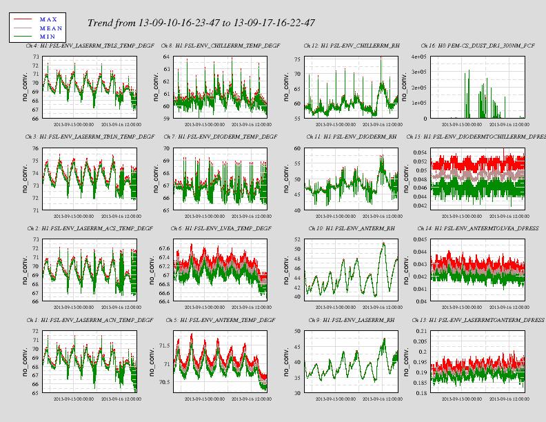
DougC and RickS

On Tuesday, we measured the minute trends of the environmental channels over the past week (see attached figure).  Ch. 16 is (supposedly) the particle counter in the H1 Diode Room.  Either the dust monitor is malfunctioning, or we are having a lot of dust events at the 100,000 count level.
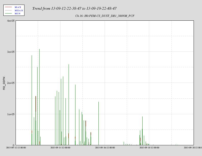
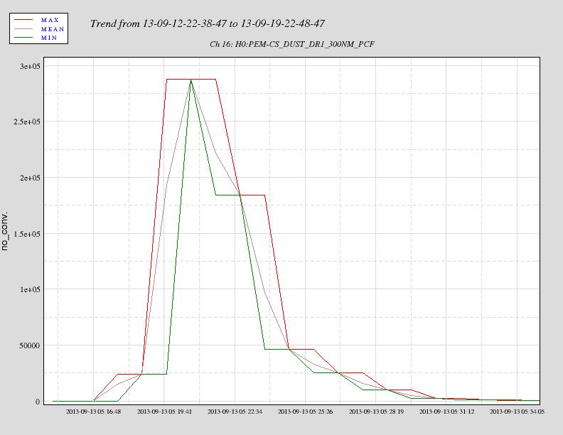
Bugzilla ID 413 has been opened to address this apparent H1 Diode Room dust glitch issue.
Attached are two plots, the first the trend of the particle counter (supposedly in the H1 Diode Room) over the past week and the second a detail of one of the glitches.
Did anyone enter the diode room and look at this dust monitor?
Filiberto, Frank, Thomas

This morning we tested the continuity and shined a flashlight on each of the PDs to get a response.

PD forward voltage:
Pin3&4:      0.415V
Pin7&6:      0.418V
Pin10&9:     0.417V
Pin13&12:    0.417V

We tested response of each PD:
Pin3&4:      64mV to 270mv PD4
Pin7&6:      87mV to 320mV PD3
Pin10&9:     66mV to 220mV PD2
Pin13&12:    57mV to 240mV PD1

The PDs are not calibrated, and for their purposes, maybe they don't need to be but they work.
Just started a low frequency measurement on ISI-ITMY for the night.
*** HPI ***
Undamped
*** ISI ***
750mHz blend on all the DOFs (ST1 & ST2)
Control lvl1 engaged
*** SUS ***
Damped
The goal of this measurement is to collect data in order to implement some tilt correction on the ISI. Tilt correction should improve our performance at low frequencies.
This test should be done by tomorrow morning.
Just started TFs measurement for the night on BSC-ISI ETMX. The ISI is undamped, the quad and the TMS are locked.
This test should be done by 6am tomorrow morning.
Attached are plots of dust counts requested from 4 PM September 17 to 4 PM September 18.
Attached are plots of dust counts requested from 4 PM September 16 to 4 PM September 17.
I replaced the RAID card in cdsfs1 with a new one. While I had the chassis open, I took the opportunity to vacuum out all the bugs and check the interior cable connections. Even so, upon booting with the new card installed, was greeted by an I2c bus error from the RAID controller. So powered off the server and found a loose connection to the disk backplane, which I either missed earlier or knocked loose when addressing another loose cable earlier (it may also never have been connected properly, once reconnected the RAID controller showed temperature sensors previously not shown on the old controller). On reboot the RAID controller was now happy. But once the server booted the root drive mounted read only due to EXT4 filesystem journal errors. So rebooted once again, which forced a full fsck after which the root filesystem was happy. The RAID controller is now in the process of verifying the RAID; this is a slow process that will take at least a day. So far the system looks healthier, but the RAID verification process should provide a good burn in period.
The RAID verification process was complete when I arrived this morning.  I then unmounted the /raid filesystem* so I could force an fsck on it, to verify the integrity of the file structure itself.  The fsck passed, so I remounted /raid.  It should now be ready to run rsyncs/backups again.  I also started the battery backup test on the RAID controller, this takes 'up to 24 hours' to complete.  During this time, if the entire system loses power without a clean shutdown, the contents of any data in flight in the RAID cache will be lost; the system is on UPS power so this is a low risk.

* I had to modify /etc/exports first to remove /raid, then run exportfs -ra to update NFS; otherwise you get 'filesystem busy' messages.  Then the reverse of course when the fsck was finished.
The battery backup test passed with an estimated capacity of 255 hours; so the controller can maintain data in the cache for roughly 10 days without external power. I also checked the controller logs, and so far they are clean with no errors.

Some details :
I used the laser which was already setup for the reference cavity and squeezer experiment in the OSB lab. Conveniently there was a PBS already setup after a Faraday on the table and I used it for specifying the polarization of the beam. I put a pick off high reflector in both the transmitted and reflected sides of the PBS so that I don't destroy the existing setup. Then I directed these beams aside and put the BS that I wanted to measure. The incident angle of the beam should be pretty close to 45 deg with an accuracy of 1 deg or so. This was established by comparing the ray trace with the hole locations on the table. Also I put an ND1 attenuator to reduce the power to less than 100 mW so that my power meter can handle.
I measured the power of both reflected and transmitted light of the BS using the Ophir handy power meter. I assumed that loss is very small.
For S -polarization I obtained the following two numbers (also as shown in the attachment ):
R = 42.8 mW / 43.1 mW = 99.3 % and R = 1 - 213.1 uW / 43.1 mW = 99.5 %.Therefore a plausible reflectivity can be
R = (99.3 % + 99.5%) / 2 = 99.4 %.The estimated deviation of this mean value is
sqrt( (99.3 % - 99.4%)^2 + (99.5% - 99.4%)^2 ) / sqrt(2) = 0.1 %.In summary R at S-pol is
99.4 +/- 0.1 %I applied the same procedure for P-pol and obtained
94.8 +/- 0.9 %. This number is close to the specification which is "95 % P-pol".I have added this result in DCC as a supplimental document. See E1000871-v1.