(Cheryl, Corey, Jeff B., Lisa, Virginio)
EX TMS Lab
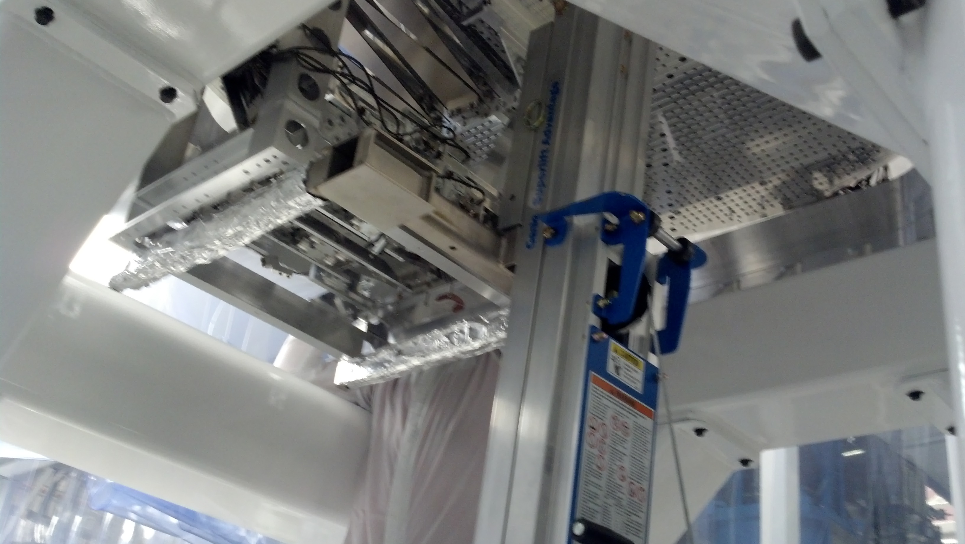
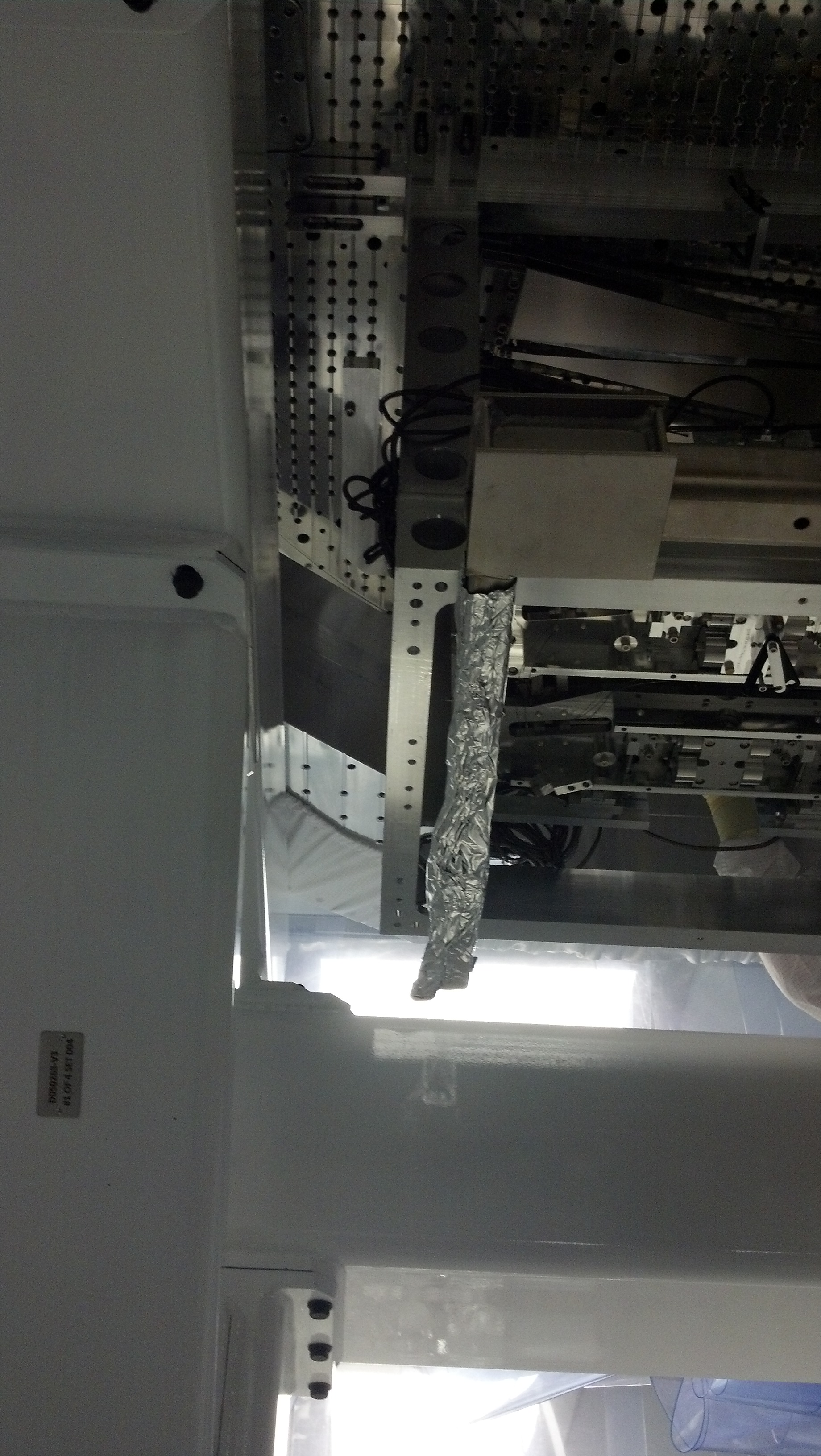
As of yesterday, this lab is now primed and ready to go. We are requiring full cleanroom suits to enter. The AC could be better (it's a little warm in there). We now have parts out and are begining to build TMS Sub-Assys. Pictures of the Lab are here.
All of this morning, Virginio and I unbagged parts and set up the lab for assembly.
TMS In-Vac Table Assy
Started building this Assy today. As I was building it, I noticed we did not have vented washers, so I called it a day and started a search---I think we should be fine. Want to get this assembly built ASAP so Lisa & Matt can layout optics on this Table (Lisa started cleaning small optics yesterday).
TMS Telescope Assy
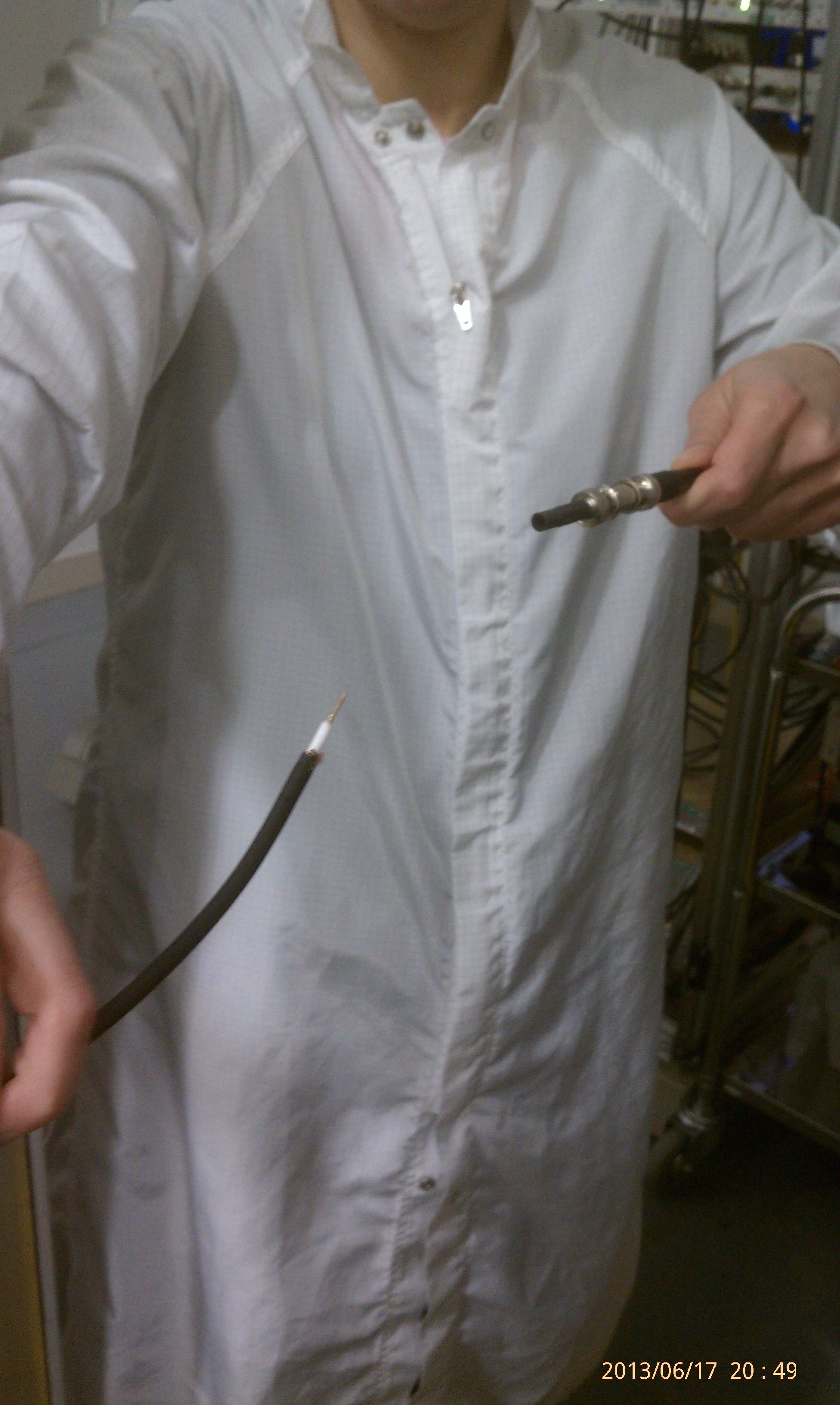
Virginio has started this assembly. Upon building, he noticed one of the Teletube Assys had spots of rust on it. We have India Tubes, so he swapped it with an extra one. (does rust on a part mean we do NOT want it in the vacuum system??). Pictures of the rusty Tube are here.
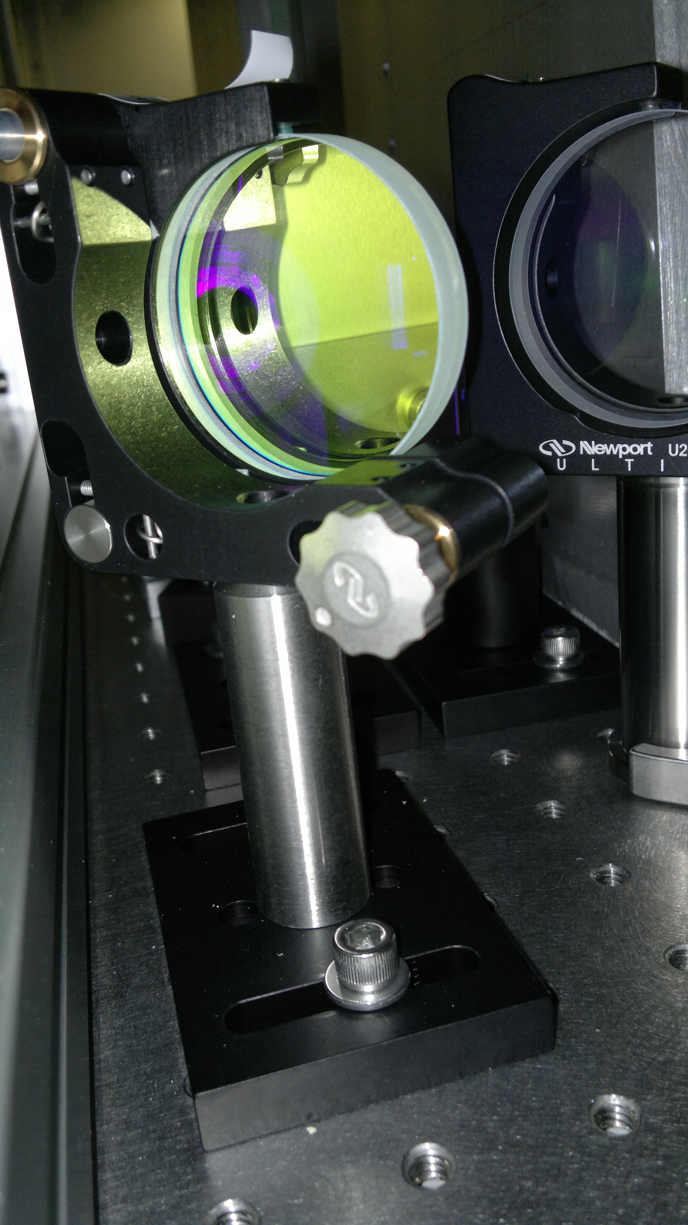
Damage to 9" Parabolic Telescope Mirror Container
Yesterday I received a box which had a Pelican box (internally-cushioned hard suit case) with all four of the Mirrors for the Telescope. Unfortunately, we discovered that the 9" Parabolic Mirror (the biggest one) was in a plastic container which failed. The container cracked and the mirror looks liked it bumped about in the container during its trip to LHO. There are noticeable particulates on all surfaces of the mirror. And there also looks to be a big scuff mark on the edge of the front surface from where the mirror rubbed against the container.
The plan is to move on and clean all four optics. Hopefully the big optic is useable.
Pictures of the optics are here.
Receiving Of TMS Parts
We've been deluged with TMS parts last week and this week, and between Cheryl, Jeff, and myself, we've beeing doing our best to keep the TMS wave at bay. :)