bubba.gateley@LIGO.ORG - posted 15:32, Friday 23 August 2013 (7523)
Apollo crew
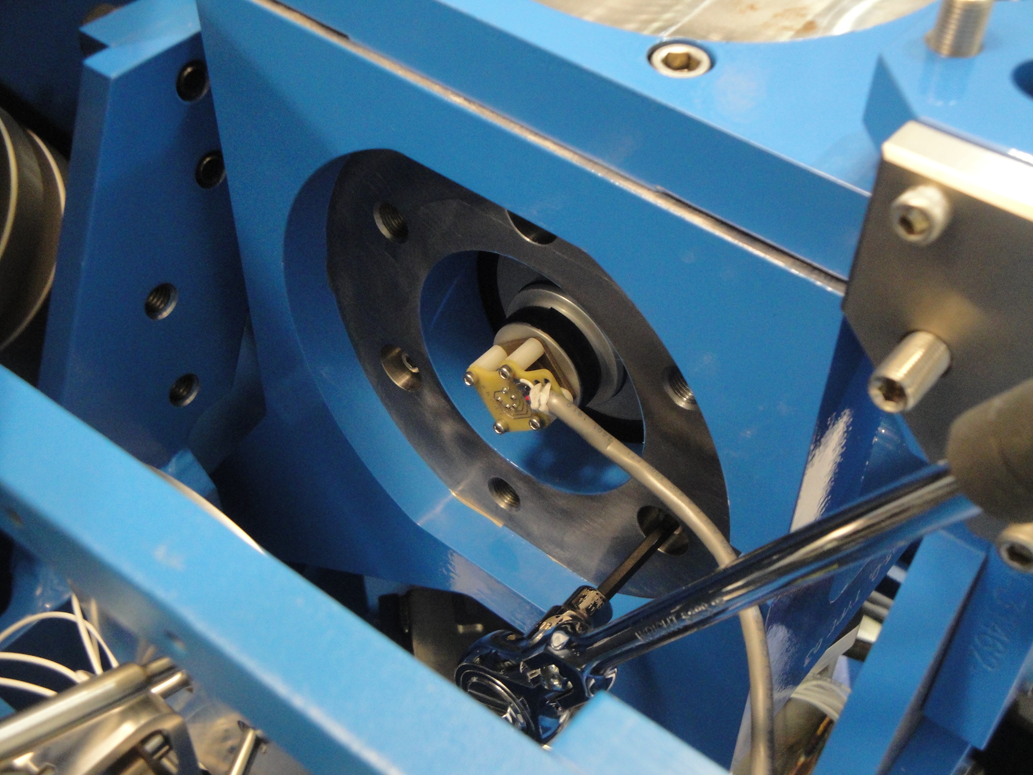
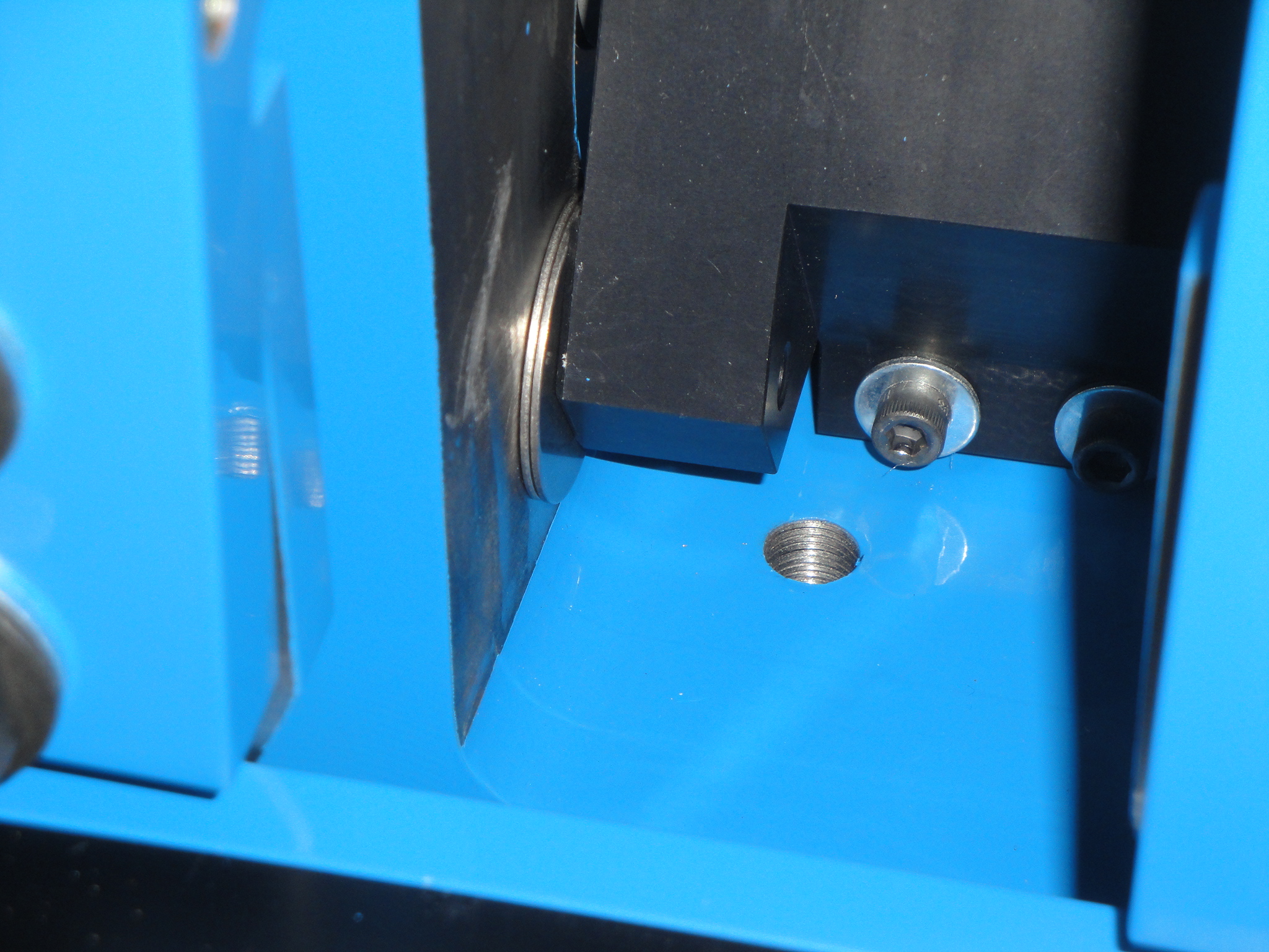
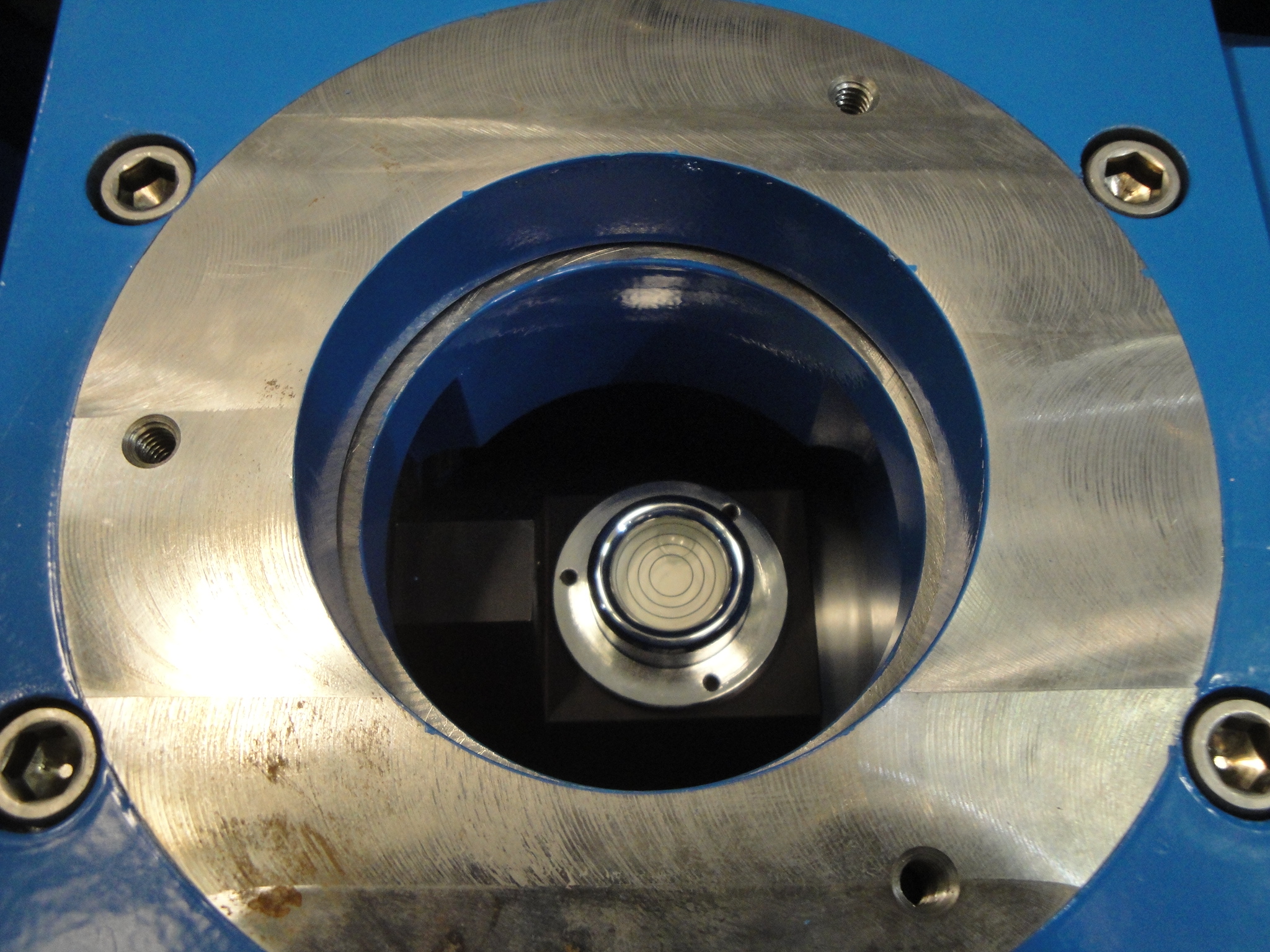
Today we finished disassembly of the work platform @ end y and transported to hi bay and after wipedown, transported into LVEA. Took measuremeants to verify placement of work platform and clean room. Will begin assembly Monday.
Tyler completed the modifications of the baffles for Thomas V and got them off to C&B.
Rick S and myself went to E Y to verify the breadboard placement on the leaner pier. We clamped the breadboard/jig in place and will possibly weld on Monday.