Over the past week or so after we first get locked, our range starts out a bit lower than previously, then as we thermalize it will climb back to our usual 155Mpc (example). Sheila has some scripts that can compare the range integrands of different points in time (alog76935). I ran the script comparing 30 min into the July 11 0550 UTC lock and 3.5 hours into the same lock after we have thermalized. These point 20-50Hz or so as the largest area of change during that thermalization time. This is roughly what we see with our DARM BLRMS as well. Based on this frequency range we are thinking that the PRCL FF and A2L could be improved to help this, the former getting updated today (alog79035), but the we lost lock before A2L could be ran.
Ibrahim, Rahul
BOSEM counts have been visibly drifting over the last few days since I centered them last week. Attached are two screenshots:
I think this can easily be explained by Temperature Driven Suspension Sag (TDSS - new acronym?) due to the blades. (Initially, Rahul suggested maybe the P-adjuster was loose and moving but I think the cyclic nature of the 8-day trend disproves this)
I tried to find a way to get the temp in the staging building but Richard said there's no active data being taken so I'll take one of the thermometer/temp sensors available and place it in the cleanroom when I'm in there next, just to have the available data.
On average, the OSEM counts for RT and LF, the vertical facing OSEMs have sagged by about 25 microns. F1, which is above the center of mass, is also seeing a long-term drift. Why?
More importantly, how does this validate/invalidate our OSEM results given that some were taken hours after others and that they were centered days before the TFs were taken?
Ibrahim
Taking new trends today shows that while the suspension sag "breathes" and comes back and forth as the temperature fluctuates on a daily basis, the F1 OSEM counts are continuing to trend downwards despite temperature not changing peak to peak over the last few days.
This F1 OSEM has gone down an additional 670 cts in the last 4 days (screenshot 1). Screenshot 2 shows the OSEM counts over the last 11 days. What does this tell us?
What I don't think it is:
What it still might be:
Next Steps:
TJ, Jennie W and I were preparing to test A2K decoupling at 12Hz, to compare to our results at 20-30Hz. For this reason we added a notch to ISCINF P and Y for all 4 quads at 12Hz. We had an unexplained lockloss while we were editing the notch filter, so we've loaded these in preparation for testing A2L decoupling next time we have a chance.
Lock loss 1404770064
Lost lock during commissioning time, but we were between measurements so it was caused by something else. Looking at the lock loss tool ndscopes, ETMX has that movement we've been seeing a lot of just before the lock loss.
We turned on the PRCL FF measured in 78940, the injection shows improvement (plot) and the range appears to have improved 1-2MPc.
In 78969 Sheila shows that PRCL noise was directly coupling to DARM rather than though SRCL/MICH.
Ibrahim, Rahul
This alog follows alog 79032 and is an in-depth investigation of the F3 OSEM's percieved instability.
From last alog:
"The nicest sounding conclusion here is that something is wrong with the F3 OSEM because it is the only OSEM and/or flag involved in L, P, Y (less coherent measurements) but not in the others; F3 fluctuates and reacts much more irratically than the others, and in Y, the F3 OSEM has the greatest proportion of actuation than P and a higher magnitude than L, so if there were something wrong with F3, we'd see it in Y the loudest. This is exactly where we see the loudest ring-up."
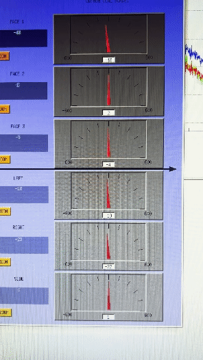
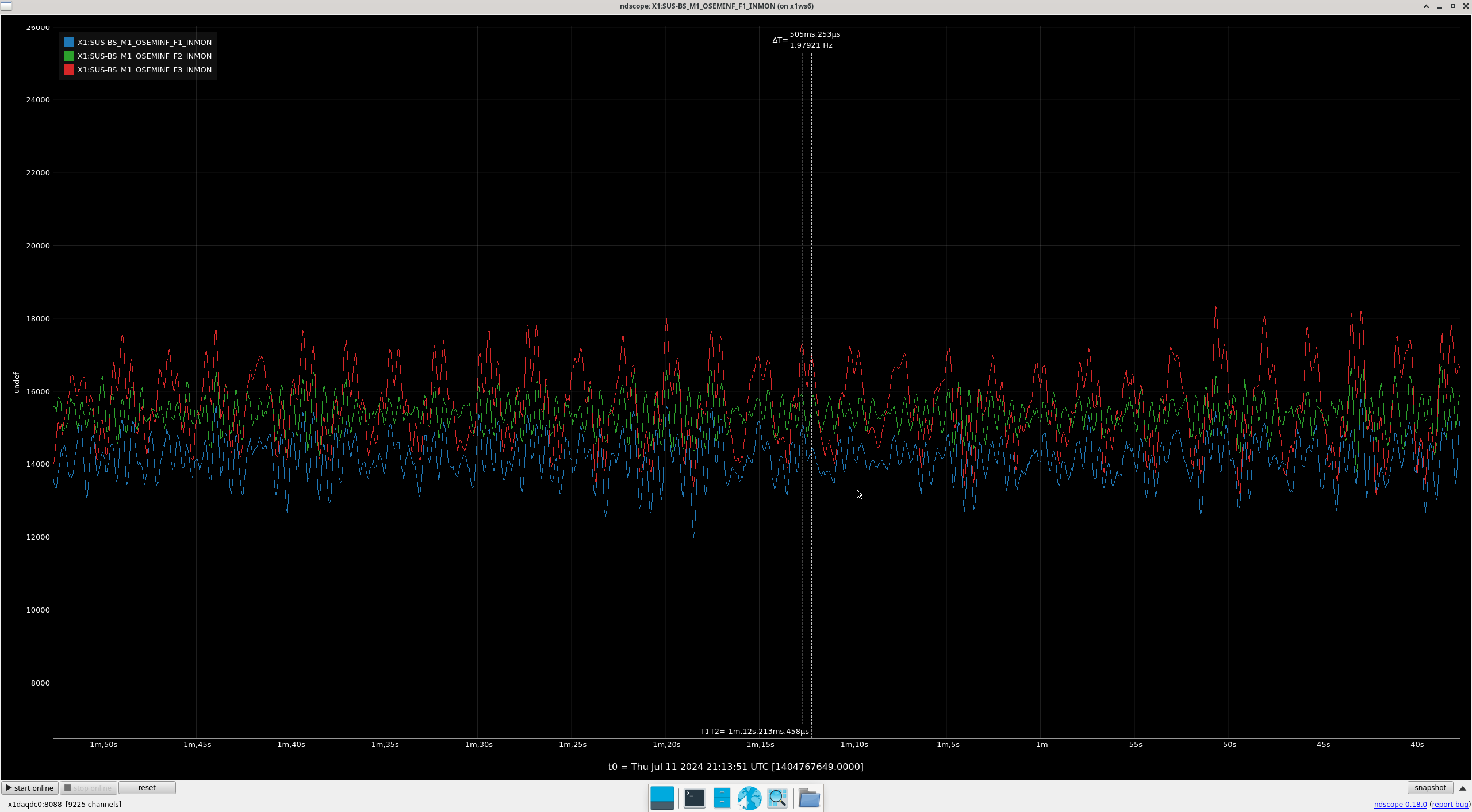
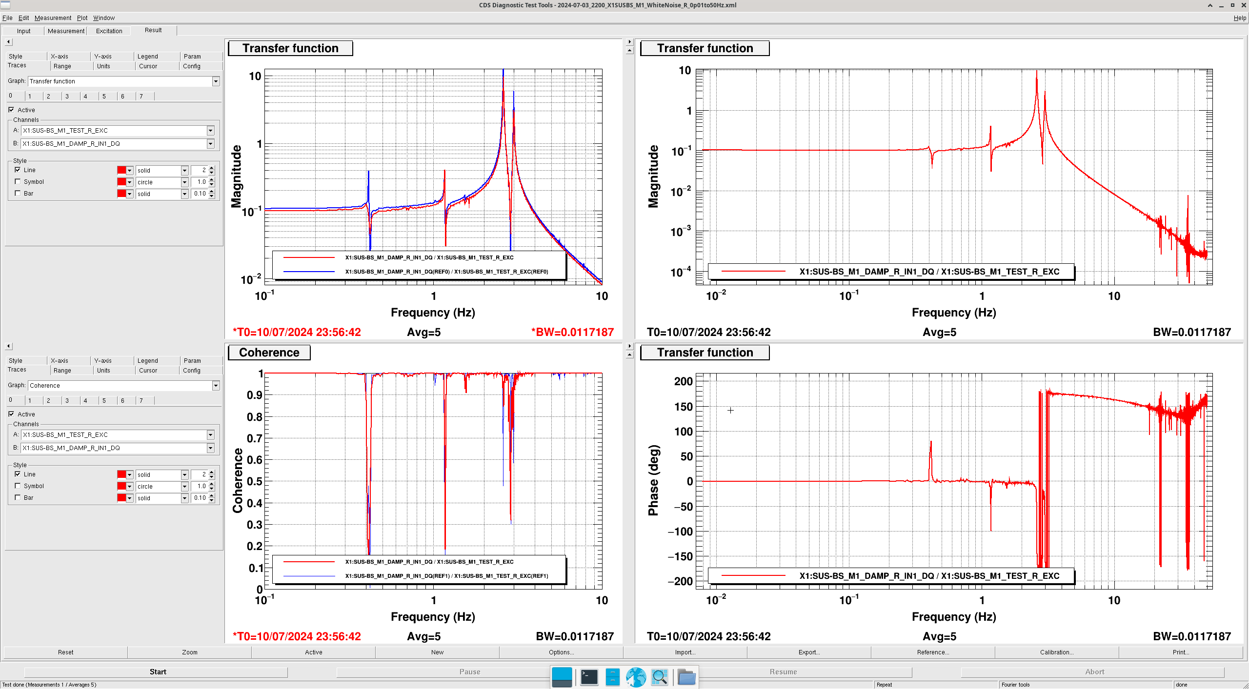
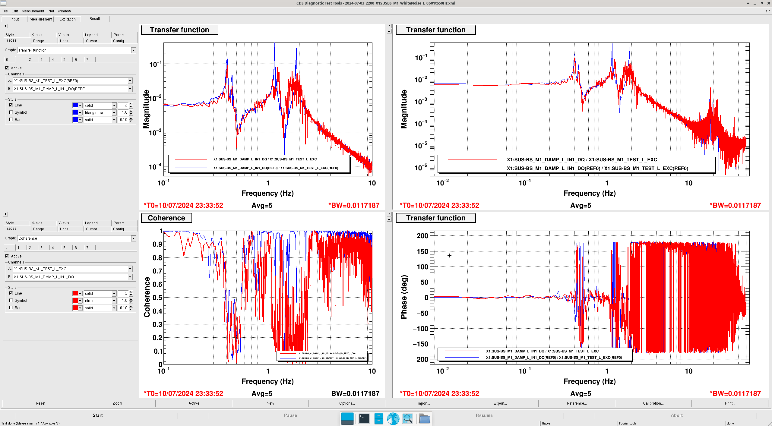
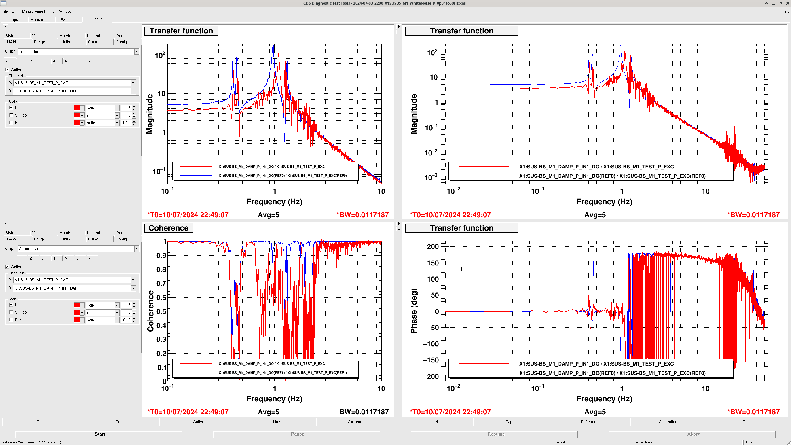
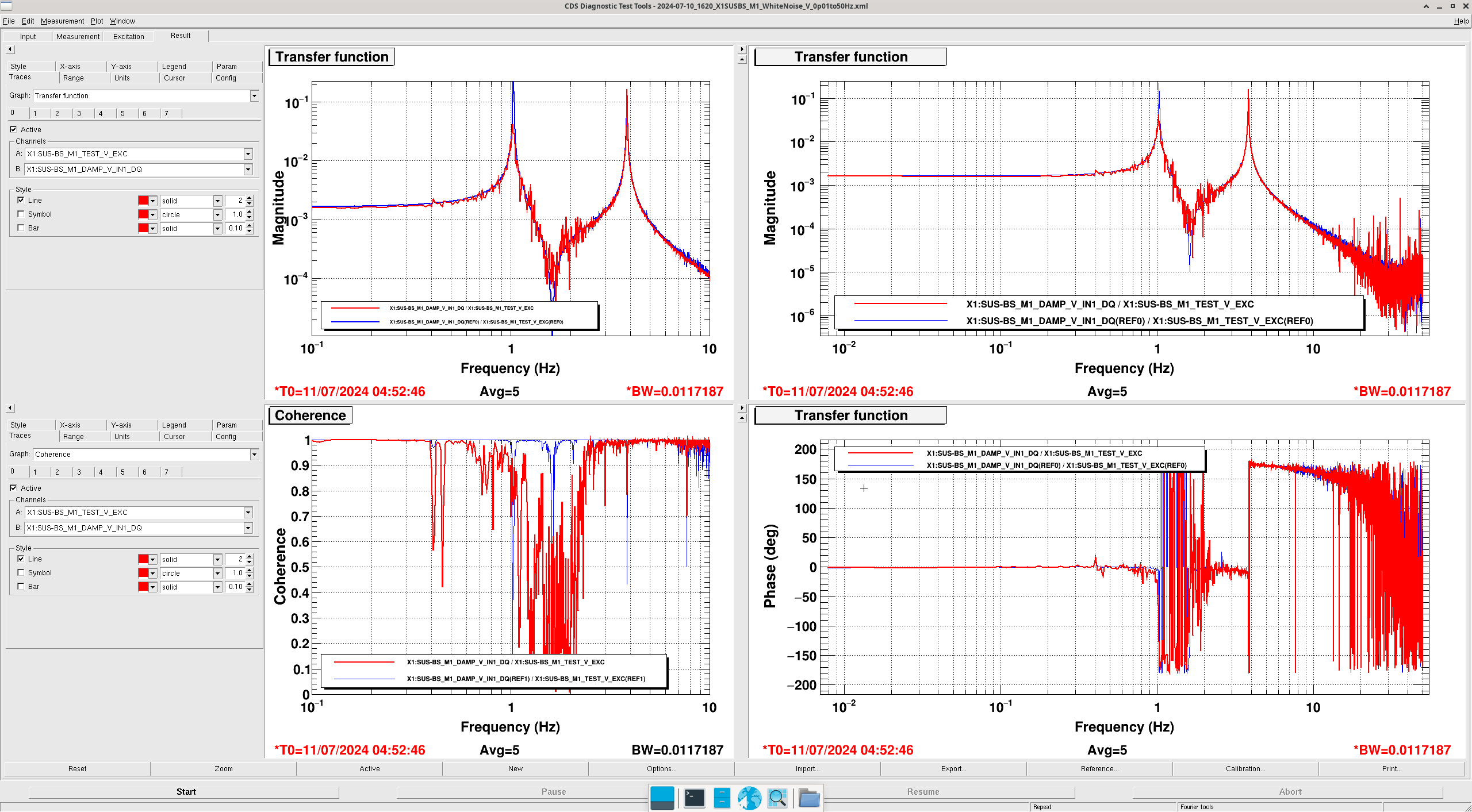
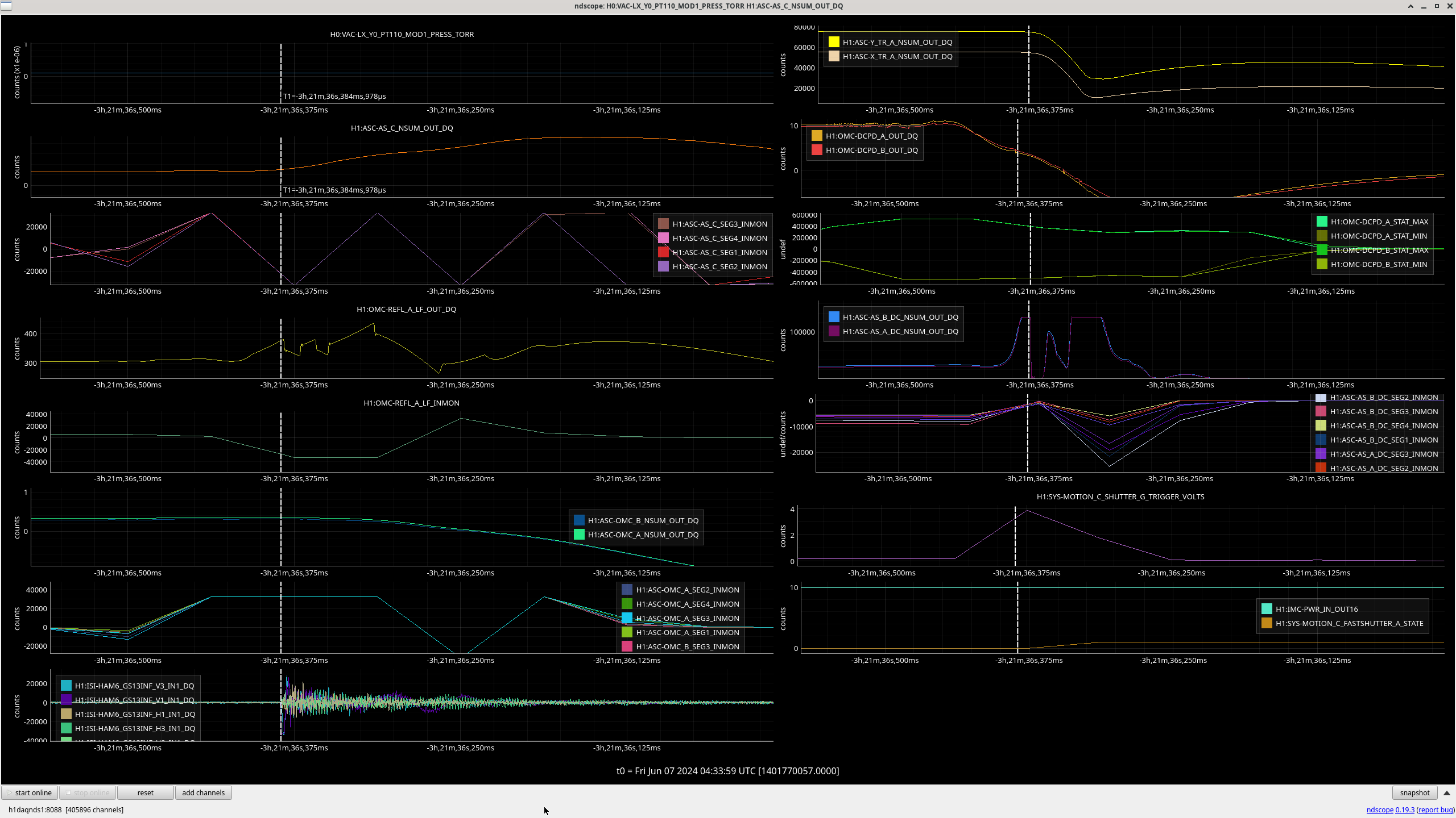
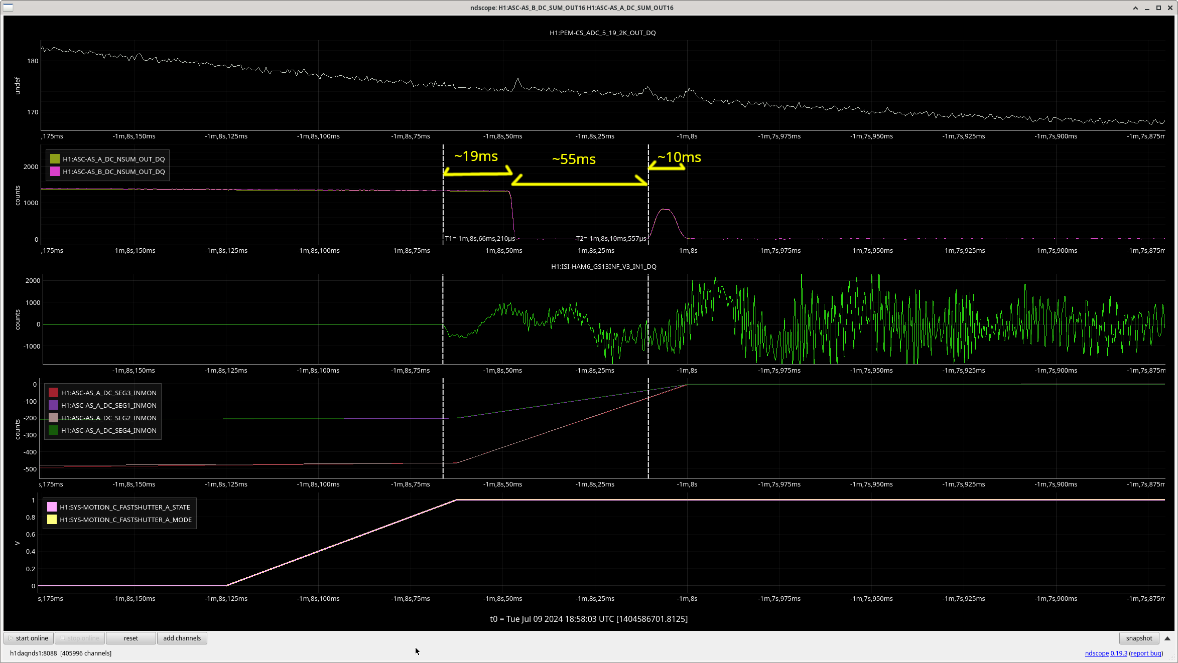
I have attached a gif which shows the free-hanging F3 OSEM moving much more than the others and percieveably so. I have also attahched an ndscope visualization of this movement, clearly showing that F3 is actuating harder/swinging wider than F1 and F3 (screenshot 1). This was percieved to a higher degree during the TF excitations and my current guess is that this is exactly what we're seeing in terms of the 1.5-6hz noisiness that is persistent in all of our TFs in varying degrees. Note that this does not need to be a sensor issue but could be a mechanical issue whereby an instability rings modes along this frequency and this OSEM is just showing us this in the modes that it rings up/actuates against the most. i.e. P, L and Y.
Investigation:
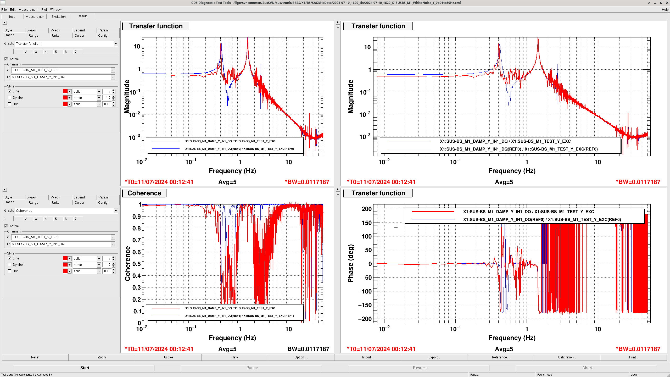
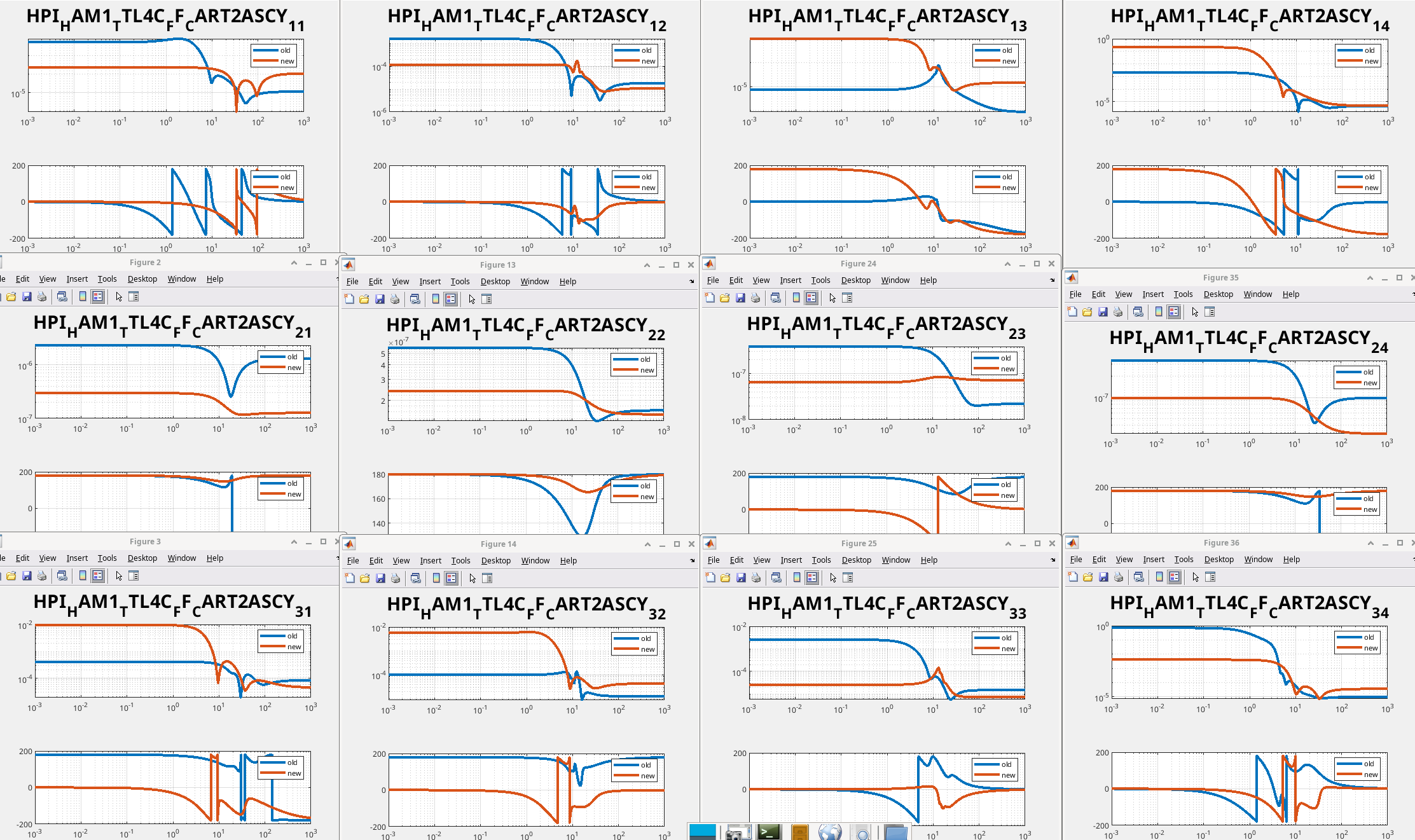
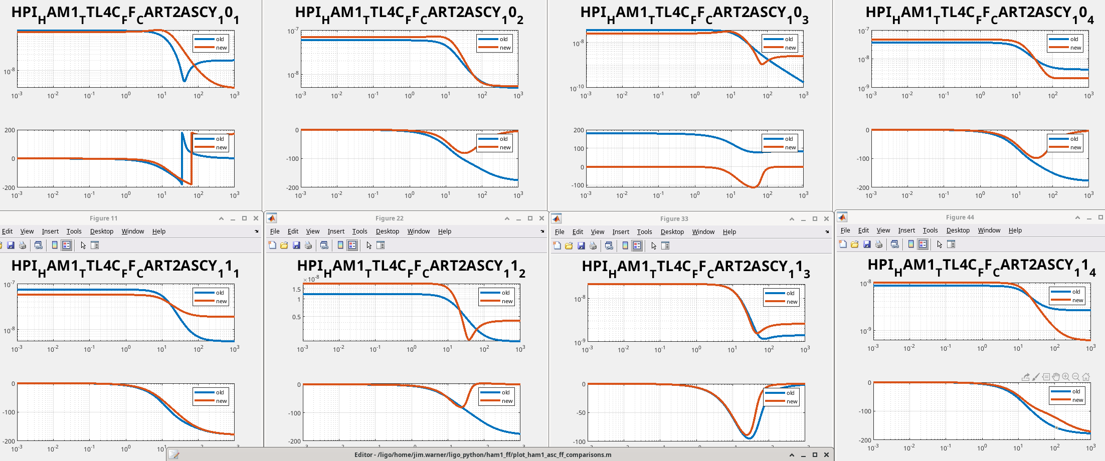
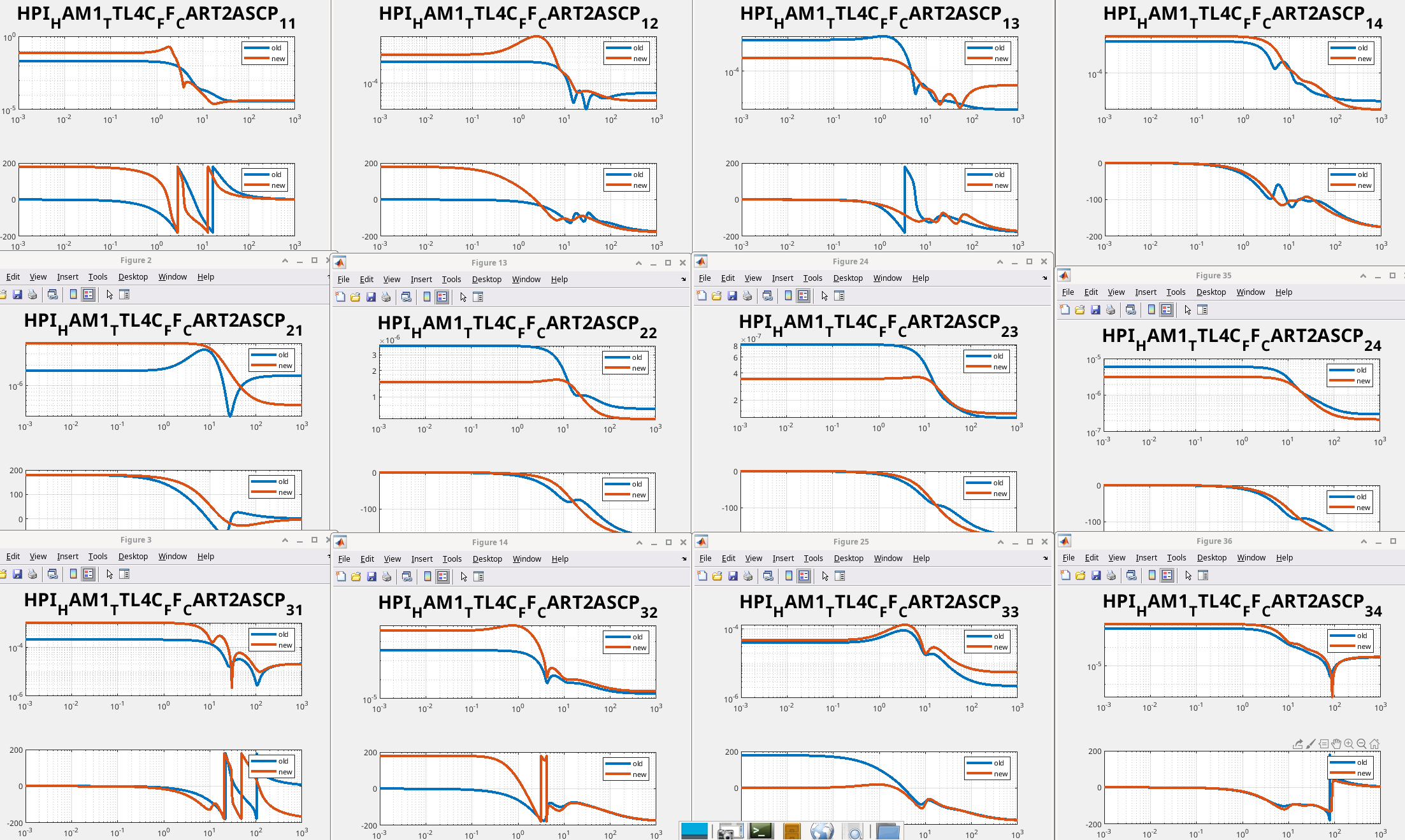
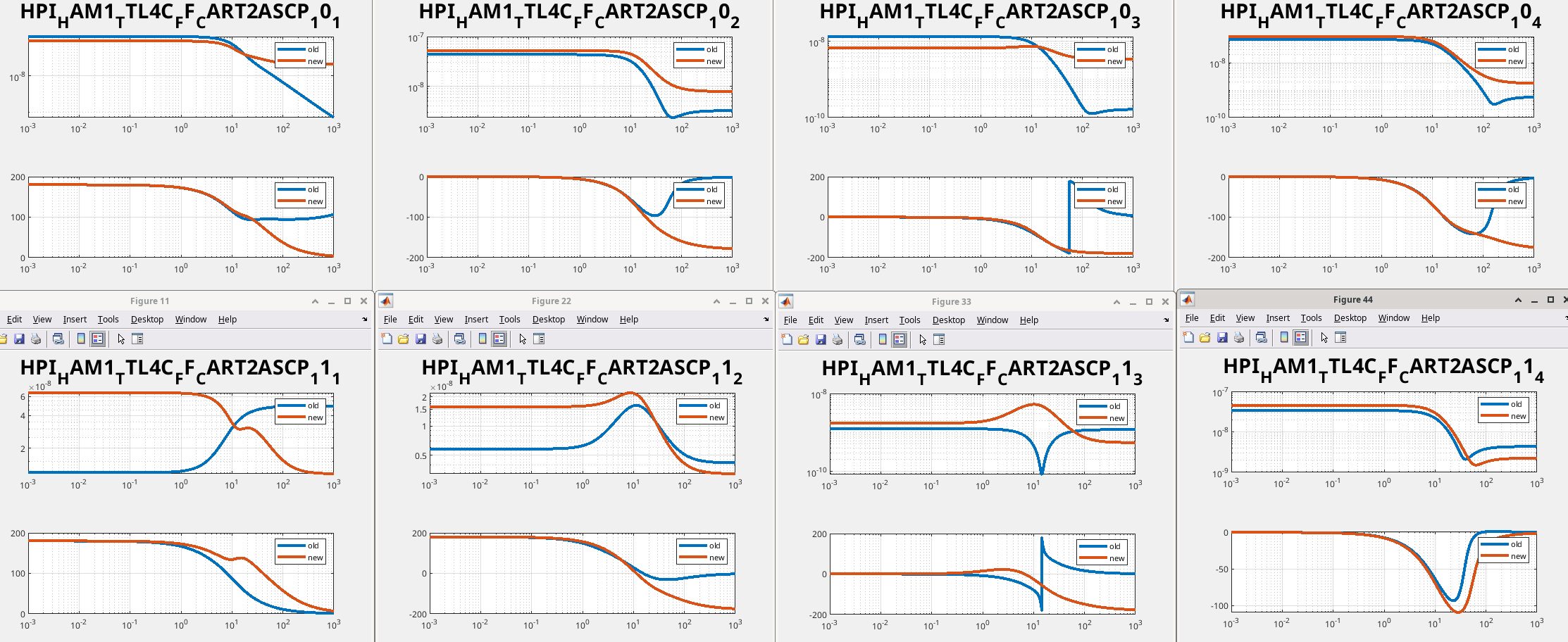
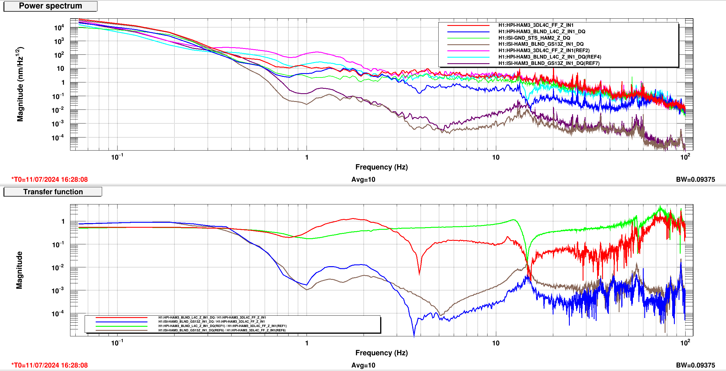
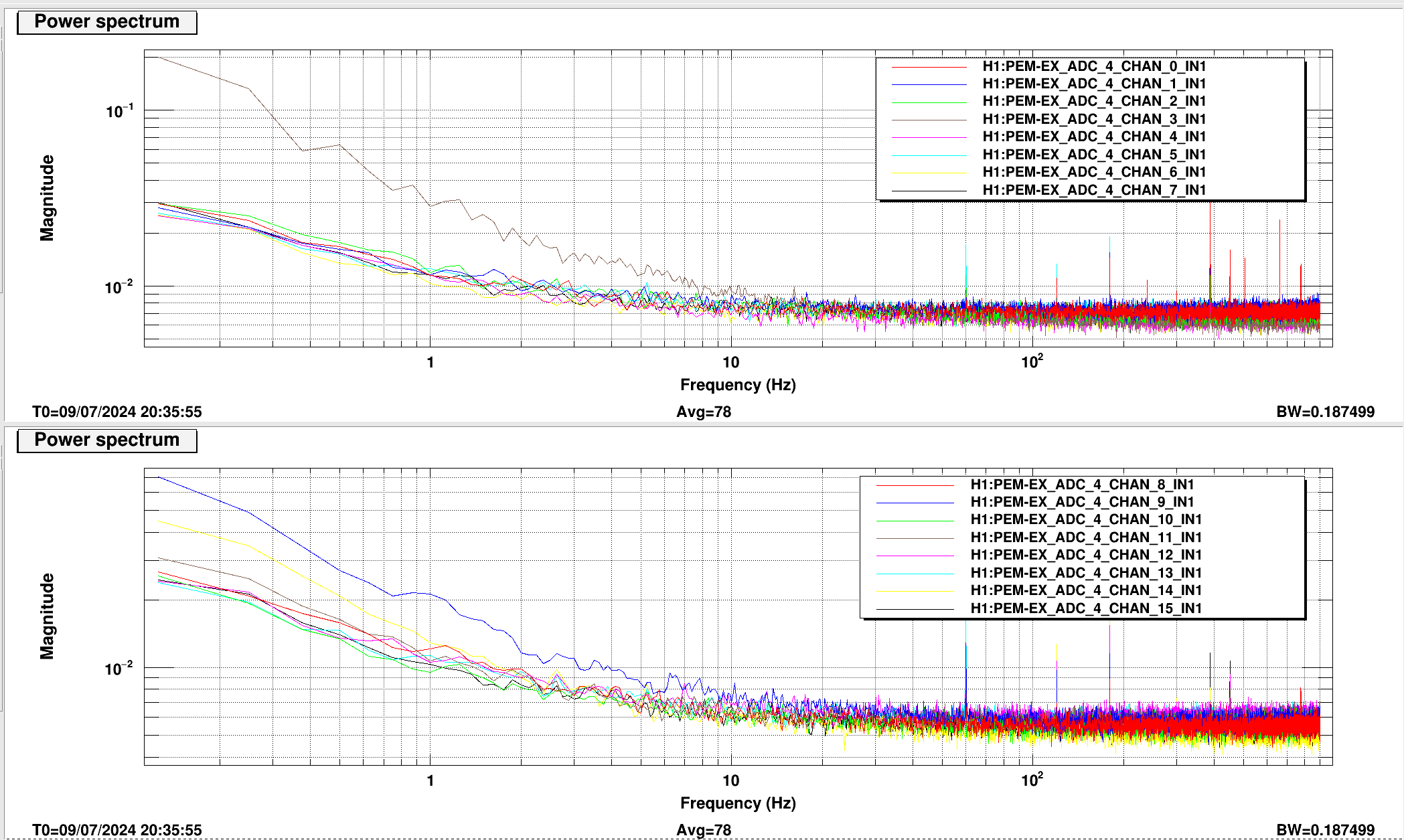
The first thing I did was take the BOSEM noise spectra whilst also having F1 and F2 as stable controls. While slightly noisy, there was no percieved discrepancy between the spectra (screenshot 2). There are some peaks and troughs around the problem 1.5-6hz area though but I doubt these are too related. In this case, we may have a mechanical instability on our hands.
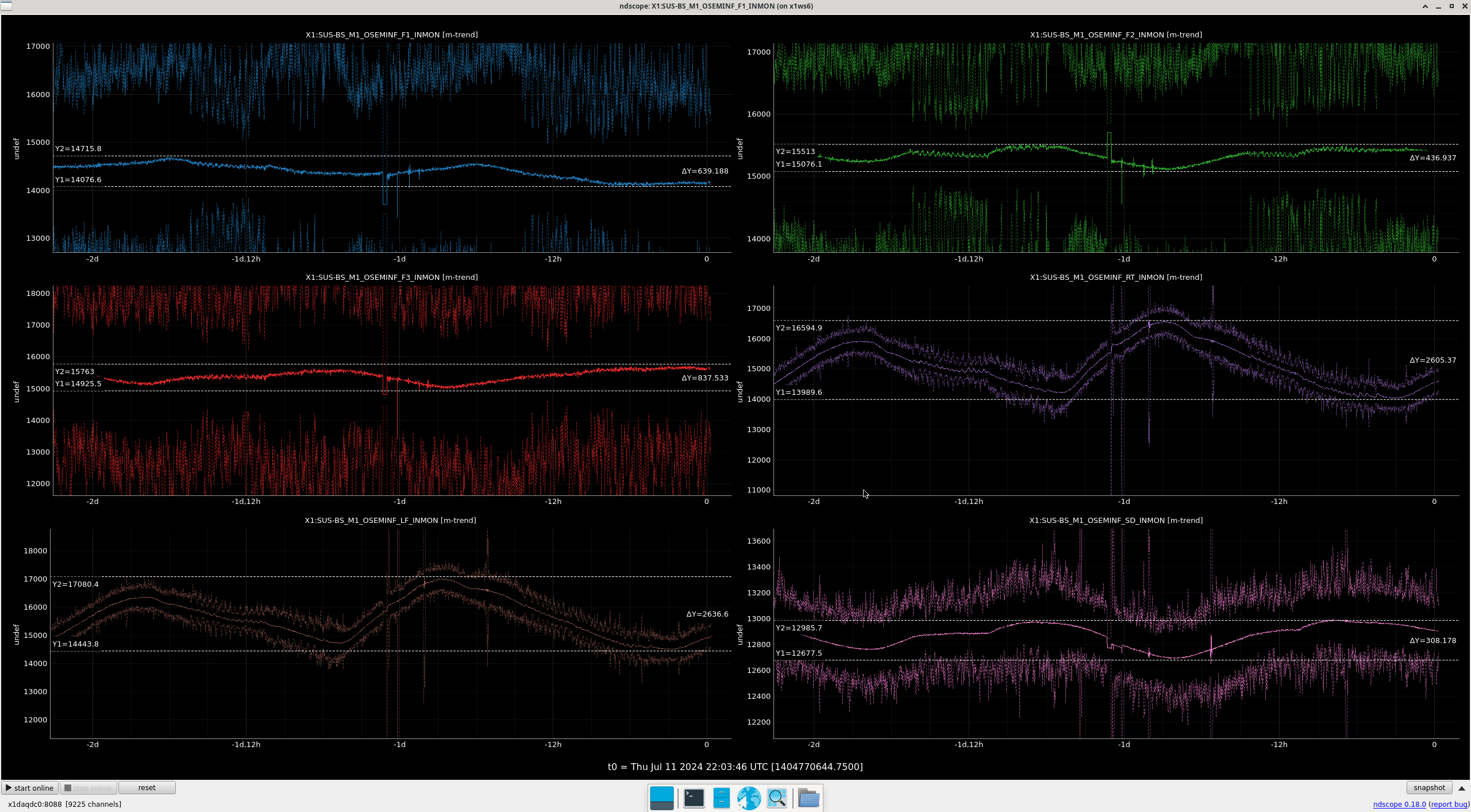
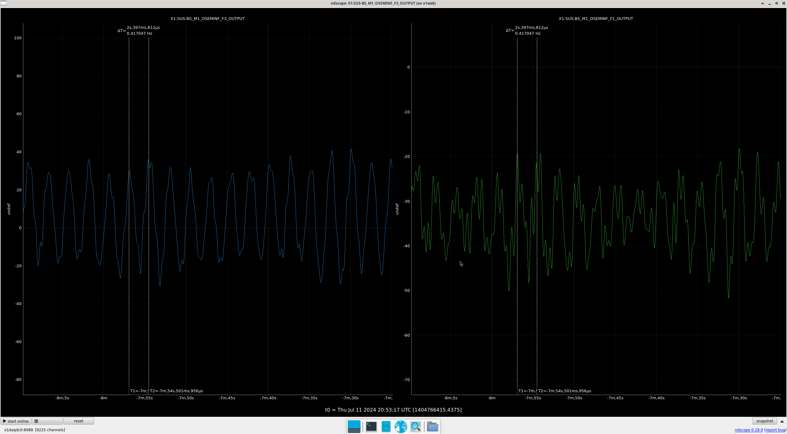
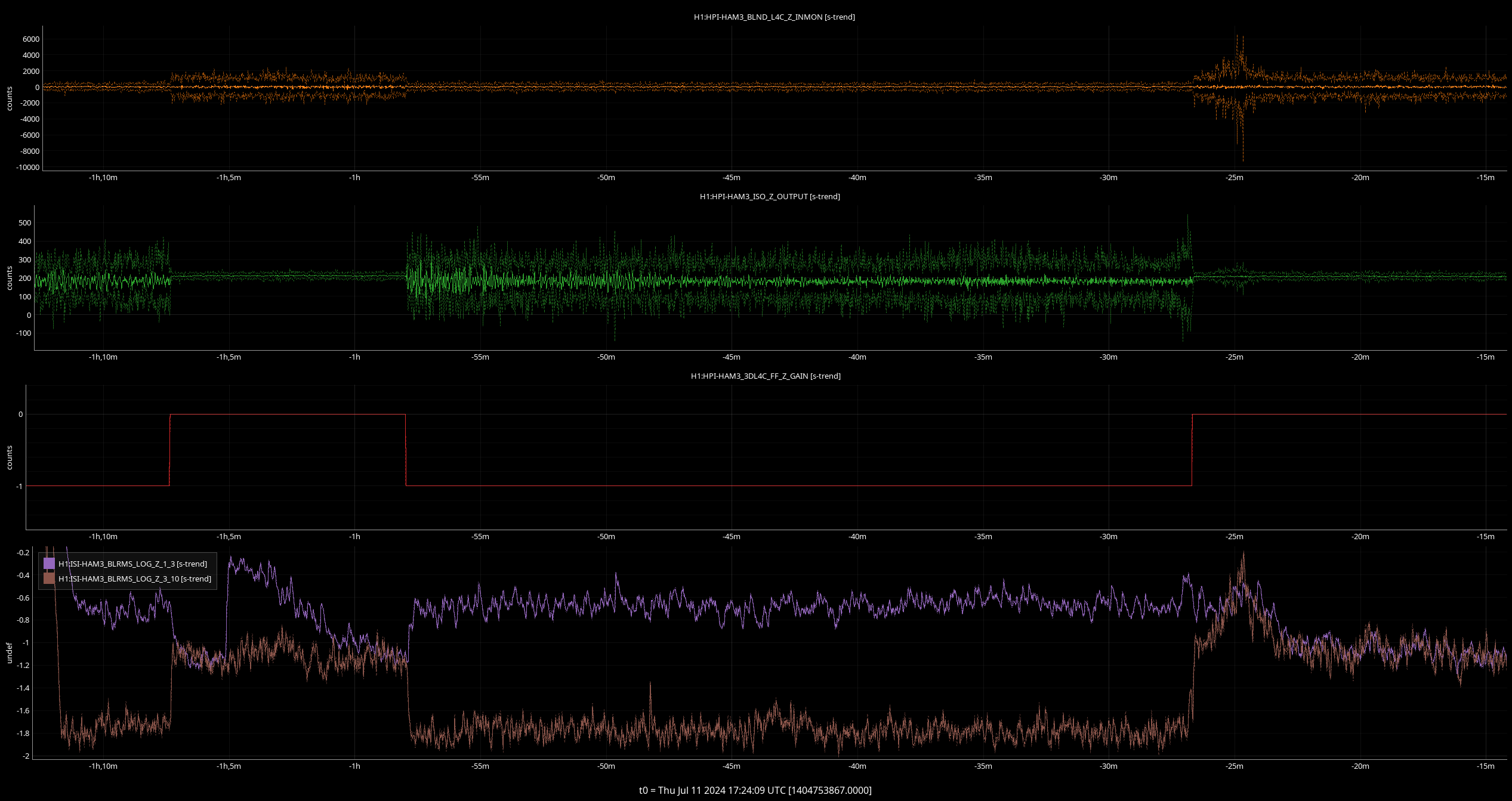
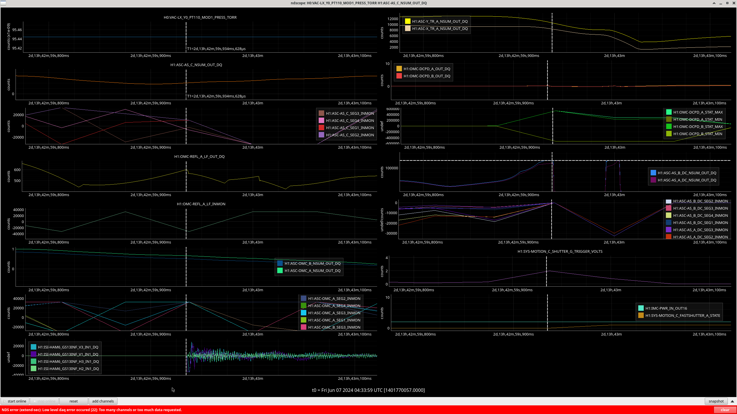
The next thing I did was trend the F1 and F3 OSEMs to see if one is percieveably louder than the other but they were quite close in their amplitudes and the same in their freq (0.4hz) (screenshot 3). I used the micron counts here.
The last and most interesting thing I did was take another look at the F3, F2 and F1 trend of the INMON count (screenshot 1) and indeed it shows that F3 oscillation does take place at around 2Hz, which is where our ring-up is loudest across the board. Combined with the clean spectra, this further indicates that there is a mechanical issue at these frequencies (1.5-6hz).
Rahul suggested that maybe the pitch adjuster was unlocked and was causing some differential pitch as the OSEMs tend to catch up and this may be the case, so I will go check this soon. This pitch adjuster thing also may affect another issue we are having, which is OSEM Count Drift (a seperate alog, coming soon to a workstation near you).
Conclusion:
There must be an issue, not with the sensor systems, but mechanically. Due to a recent history in hysteresis, this may be the case on a less percieveable level. Another potential culprit is rising Staging Building temps differentially screwing with blades(Rahul's thought since there was a measured 2F change between yesterday and 3 days ago). Will figure out next steps pending discussion with the team.
Ibrahim, Oli
Attached are the most recent (07-10-2024) BBSS Transfer Functions following the most recent RAL visit and rebuild. The Diaggui screenshots show the first 01-05-2024 round of measurements as a reference. The PDF shows these results with respect to expectations from the dynamical model. Here is what we think so far:
Thoughts:
The nicest sounding conclusion here is that something is wrong with the F3 OSEM because it is the only OSEM and/or flag involved in L, P, Y (less coherent measurements) but not in the others; F3 fluctuates and reacts much more irratically than the others, and in Y, the F3 OSEM has the greatest proportion of actuation than P and a higher magnitude than L, so if there were something wrong with F3, we'd see it in Y the loudest. This is exactly where we see the loudest ring-up. I will take spectra and upload this in another alog. This would account for all issues but the F1, LF and RT OSEM drift, which I will plot and share in a seperate seperate alog.
We have also now made a transfer function comparison between the dynamical model, the first build (2024/01/05), and following the recent rebuild (2024/07/10). These plots were generated by running $(sussvn)/trunk/BBSS/Common/MatlabTools/plotallbbss_tfs_M1.m for cases 1 and 3 in the table. I've attached the results as a pdf, but the .fig files can also be found in the results directory, $(sussvn)/trunk/BBSS/Common/Results/allbbss_2024-Jan05vJuly10_X1SUSBS_M1/. These results have been committed to svn.
Turned off HAM1 asc feedforward on cli by:
caput H1:HPI-HAM1_TTL4C_FF_INF_RX_GAIN 0 & caput H1:HPI-HAM1_TTL4C_FF_INF_RY_GAIN 0 & caput H1:HPI-HAM1_TTL4C_FF_INF_X_GAIN 0 & caput H1:HPI-HAM1_TTL4C_FF_INF_Z_GAIN 0 &
Turned back on just after 1404765655.
caput H1:HPI-HAM1_TTL4C_FF_INF_RX_GAIN 1 & caput H1:HPI-HAM1_TTL4C_FF_INF_RY_GAIN 1 & caput H1:HPI-HAM1_TTL4C_FF_INF_X_GAIN 1 & caput H1:HPI-HAM1_TTL4C_FF_INF_Z_GAIN 1 &
I've run Gabriele's script AM1_FF_CHARD_P_2024_04_12.ipynb from this alog on the window with the HAM1 asc ff off. I don't have a good feel for when the script produces good or bad filters, so I wrote them to copy of the seiproc foton file in my directory and plotted the current filters against the new filters. There are a lot of these, many of them are very small magnitude so I'm not sure some of them are doing anything. But none of the new filters are radically different from the old filters. I'll install the new filters in seiproc in FM7 for all the filter banks with a date stamp of 711, but won't turn them on yet. We can try next week maybe, unless Gabriele or Elenna have a better plan.
On Tuesday, I added some spare vertical L4Cs under HAM3 to try doing the 3dl4c feedforward that we've used on HAM1. While the earthquake was ringing down this morning, I tried turning on some feed forward filters I came up with using Gabriele's interactivefitting python tool (SEI log). The feedforward to HEPI works, doesn't seem to affect the HEPI to ISI feedforward. There is some gain peaking at 1-3hz, so I will take a look at touching up the filter in that band, then try again.
First attached image are some trends for the test. Top two traces are the Z L4C and position loop output during the test. The third trace is the gain for the feedforward path, it's on when the gain is -1, off when the gain is 0. Bottom trace are the 1-3hz and 3-10hz log blrms for the ISI Z Gs13s. The HEPI L4Cs and ISI GS13s both see reduced motion when the feedforward is turned on, but the is some increased 1-3hz motion on the ISI.
Second image are some performance measurements, top plot are asds during the on (live traces) and off (refs) measurements. This was done while the 6.5 eq in Canada was still ringing down so the low frequency part of the asds are kind of confusing, but there is clear improvement in both the HEPI BLND L4C and ISI GS13s above 3 hz. Bottom plot are transfer functions from the 3DL4C to HEPI L4C and ISI GS13, these do a better job accounting for the ground motion from the earthquake. Red (3dl4c to HEPI l4c tf) and blue (3dl4c to ISI GS13 tf) are 3dl4c feedforward on, green (3dl4c to HEPI l4c tf) and brown (3dl4c to ISI GS13 tf) are 3dl4c feedforward off. Sensor correction was off at this time, but HEPI to ISI feedforward was on. It seems like the 3dl4c feedforward makes the HEPI and ISI motion worse by a factor of 3 or 4 at 1 to 2hz, but reduces the HEPI motion by factors of 5-10x from 4 to 50hz. The ISI motion isn't improved as much, maybe because the feedforward to HEPI is affecting the HEPI to ISI feedforward. I might try this on HAM4 or HAM5 next.
A couple of HAM triple suspensions tripped this morning, while the 6.5 eq off of Vancouver island was rolling by. Looking at trends for SRM, M3 tripped because the ISI tripped and cause the optic to saturate the M3 osems. The ISI trip happened after the peak of the ground motion, when some of the CPS saturated, due to the large low frequency motion. I think we could have avoided this by switching to higher blends, when SEI_ENV went to it's LARGE_EQ state. TJ added this to the guardian, but it looks like HAM7 and HAM8 might not be stable with those blends. I'll have to do some measurements on those two chambers to see what is causing those blends to be unstable, when I have time.
First attached trend are a short wind around the time of the ISI trip. The M3 osems don't see much motion until the ISI trips on the CPS, and SRM doesn't trip until a bit later, when the ISI starts saturating GS13s because of the trip.
Second image shows the full timeline. The middle row shows the peak of the earthquake has more or less passed, but the ISI CPS are still moving quite a lot. The GS13 on the bottom row doesn't saturate until after the ISI trips on the CPS.
J. Kissel, S. Koehlenbeck, M. Robinson, J. Warner The LHO install team (Jim, Mitch) -- who has experience installing in-chamber fiber optic systems -- have reviewed the two options put forth by the SPI team for optical fiber routing from some feedthrus to the future location of the SPI follower breadboard on the -X side wall of the HAM3 ISI using Eddie's mock-ups in D2400103. Both options (WHAM-D8 or WHAM-D5) are "evil" in several (but different) ways but we think the lesser of the two is running the fibers from D5 (the currently blank flange underneath the input arm beam tube on the -X side of HAM3; see D1002874). In support of this path forward, one of the primary evils with D5 is that access to it is *very* crowded with HEPI hydraulics piping, cable trays, and various other stuff. Here I post some pictures of the situation. Images 5645, 5646, 5647, 5648, 5649, 5650, 5651 show various views looking at HAM3 D5. Images 5652, 5653, 5654 show the HAM2 optical lever (oplev) transceiver, which is a part of the officially defunct HAM Table Oplev system which -- if removed -- would help clear a major access interference point.
Conda packages on the workstations were updated.
There are two bug fixes in this update
foton 4.1.2: magnitude can now be positive when creating a root using the Mag-Q style in the 's' plane.
diaggui 4.1.2: Excitation channel names weren't nested properly on the excitations tab. This has been fixed.
6.5m off the coast of Vancouver Island. One picket fence station gave us warning before it hit. We were in the process of transitioning to earthquake mode when we lost lock. All ISIs tripped and some suspensions so far.
TITLE: 07/11 Day Shift: 1430-2330 UTC (0730-1630 PST), all times posted in UTC
STATE of H1: Observing at 153Mpc
OUTGOING OPERATOR: Tony
CURRENT ENVIRONMENT:
SEI_ENV state: CALM
Wind: 3mph Gusts, 2mph 5min avg
Primary useism: 0.01 μm/s
Secondary useism: 0.06 μm/s
QUICK SUMMARY: Locked for 9 hours. Planned calibration and commissioning today from 830-1200PT (1530-1930 UTC).
We cannot make a reasonable assessment of energy deposited in HAM6 when we had the pressure spikes (the spikes themselves are reported in alogs 78346, 78310 and 78323, Sheila's analysis is in alog 78432), or even during regular lock losses.
This is because all of the relevant sensors saturate badly, and the ASC-AS_C is the worst in this respect because of heavy whitening. This happens each and every time the lock is lost. This is our limitation in configuration. I made a temporary change to partly mitigate this in a hope that we might obtain useful knowledge for regular lock losses (but I'm not entirely hopeful), which will be explained later.
Anyway, look at the 1st attachment, which is the trend at around the pressure spike incident at 10W (other spikes were at 60W, so this is the mildest of all). You cannot see the pressure spike because it takes some time for the puffs of gass molecules to reach the pirani.
Important points to take:
This is understandable. Look at the second attachment for a very rough power budget and electronics description of all of these sensors. QPDs (AS_C and OMC QPDs) have 1kOhm raw transimpedance, 0.4:40 whitening that is not switchable on top of two stages of 1:10 that are switchable. WFSs (AS_A and AS_B) have 0.5k transimpedance with a factor of 10 gain that is switchable, and they don't have whitening.
This happens with regular lock losses, and even with 2W RF lock losses (third attachment), so it's hard to make a good assessment of the power deposited for anything. At the moment, we have to accept that we don't know.
We can use AS_B or AS_A data even though they're railed and make the lower bound of the power, thus energy. That's what I'll do later.
(Added later)
After TJ locked the IFO, we saw strange noise bump ffrom ~20 to ~80 or so Hz. Since nobody had any idea, and since my ASC SUM connection to the PEM rack is an analog connection from the ISC rack that also has the DCPD interface chassis, I ran to the LVEA and disconnected that.
Seems like that wasn't it (it didn't get any better right after the disconnection), but I'm leaving it disconnected for now. I'll connect it back when I can.
In a hope to make a better assesment of the regular lock losses, I made the following changes.
My gut feeling is that these things still rail, but we'll see. I'll probably revert these on Tuesday next week.
SDF screenshot of accepted values.
Low voltage operation of the fast shutter: It still bounces.
Before we started locking IFO, I used available light coming from IMC and closed/opened the fast shutter using the "Close" and "Open" button on the MEDM screen. Since this doesn't involve the trigger voltage crossing the threshold, this only seems to drive the low voltage output of the shutter driver which is used to hold the shutter in closed position for a prolonged time.
In the attached, the first marker shows the time the shutter started moving, witnessed by GS-13.
About 19ms after the shutter started moving, the shutter is fully shut. About 25 ms after the shutter was closed, it started opening, got open or half-open for about 10ms and then closed for good.
Nothing was even close to railing. I repeated the same thing three times and it was like this every time.
Apparently the mirror is bouncing down or maybe moving sideways. During the last vent we haven't taken the picture of the beam on the fast shutter mirror, but it's hard to imagine that it's close the the end of the mirror's travel.
I thought that it's not supposed to do that. See the second movie in G1902365, even though the movie is capturing the HV action, not the LV, it's supposed to stay in the closed position.
ASC-AS_C analog sum signal at the back of the QPD interface chassis was put back on at around 18:30 UTC on Jul/11.
Unfortunately, I forgot that the input range of some of these PEM ADCs are +-2V, and so the signal still railed when the analog output of ASC-AS_SUM didn't (2V happens to be the trigger threshold of the fast shutter), so this was still not good enough.
I installed 1/11 resistive divider (nominally 909Ohm - 9.1k) on the output of the ASC-AS_C analog SUM output on the chassis (not on the input of the PEM patch panel) at around 18:30 UTC on Jul/12 2024 while IFO was out of lock.
WP11970 h1susex 28AO32 DAC
Fil, Marc, Erik:
Fil connected the upper set of 16 DAC channels to the first 16 ADC channels and verified there were no bad channels in this block. At this point there were two bad channels; chan4 (5th chan) and chan11 (12th chan).
Later Marc and Erik powered the system down and replaced the interface card, its main ribbon cable back to the DAC and the first header plate including its ribbon to the interface card. What was not replaced was the DAC card itself and the top two header plates (Fil had shown the upper 16 channels had no issues). At this point there were no bad channels, showing the problem was most probably in the interface card.
No DAQ restart was required.
WP11969 h1iopomc0 addition of matrix and filters
Jeff, Erik, Dave:
We installed a new h1iopomc0 model on h1omc0. This added a mux matrix and filters to the model, which in turn added slow channels to the DAQ INI file. DAQ restart was required.
WP11972 HEPI HAM3
Jim, Dave:
A new h1hpiham3 model was installed. The new model wired up some ADC channels. No DAQ restart was required.
DAQ Restart
Erik, Jeff, Dave:
The DAQ was restarted soon after the new h1iopomc0 model was installed. We held off the DAQ restart until the new filters were populated to verify the IOP did not run out of processing time, which it didn't. It went from 9uS to 12uS.
The DAQ restart had several issues:
both GDS needed a second restart for channel configuration
FW1 spontaneously restarted itself after running for 9.5 minutes.
WP11965 DTS login machine OS upgrade
Erik:
Erik upgraded x1dtslogin. When it was back in operation the DTS environment channels were restored to CDS by restarting dts_tunnel.service and dts_env.service on cdsioc0.
Tue09Jul2024
LOC TIME HOSTNAME MODEL/REBOOT
09:50:32 h1omc0 h1iopomc0 <<< Jeff's new IOP model
09:50:46 h1omc0 h1omc
09:51:00 h1omc0 h1omcpi
09:52:18 h1seih23 h1hpiham3 <<< Jim's new HEPI model
10:10:55 h1daqdc0 [DAQ] <<< 0-leg restart for h1iopomc0 model
10:11:08 h1daqfw0 [DAQ]
10:11:09 h1daqnds0 [DAQ]
10:11:09 h1daqtw0 [DAQ]
10:11:17 h1daqgds0 [DAQ]
10:11:48 h1daqgds0 [DAQ] <<< 2nd restart needed
10:14:02 h1daqdc1 [DAQ] <<< 1-leg restart
10:14:15 h1daqfw1 [DAQ]
10:14:15 h1daqtw1 [DAQ]
10:14:16 h1daqnds1 [DAQ]
10:14:24 h1daqgds1 [DAQ]
10:14:57 h1daqgds1 [DAQ] <<< 2n restart needed
10:23:07 h1daqfw1 [DAQ] <<< FW1 spontaneous restart
11:54:35 h1susex h1iopsusex <<< 28AO32 DAC work in IO Chassis
11:54:48 h1susex h1susetmx
11:55:01 h1susex h1sustmsx
11:55:14 h1susex h1susetmxpi
Power Spectrum of channels 0 through 15. No common mode issues detected.
Channel 3 & 9 are elevated below 10Hz
It is unclear if these are due to the PEM ADC or the output of the DAC. More testing is needed.
New plot of first 16 channels, with offsets added to center the output to zero. When offsets were turned on, the 6Hz lines went away, I believe these were due to uninitialized DAC channels. This plot also contains the empty upper 16 channels on the PEM ADC chassis as a noise comparison with nothing attached to the ADC. Channel 3 is still noisy below 10Hz.
New plot of second 16 channels (ports C & D), with offsets added to center the output to zero. This plot also contains the empty lower 16 channels on the PEM ADC chassis as a noise comparison with nothing attached to the ADC. Channel 3 is still noisy below 10Hz, signifying this to be an ADC issue, not necissarily a DAC issue. These plots seem to imply that the DAC noise desnity while driving zero volts is well below the ADC noise floor in this frequency range.
The first attachment shows spectra (GDS CALIB STRAIN clean, so with calibration corrections and jitter cleaning updated and SRCL FF retuned) with OM2 hot vs cold this week, without squeezing injected. The shot noise is slightly worse with OM2 hot, while the noise from 20-50Hz does seem slightly better with OM2 hot. This is not as large of a low frequency improvement as was seen in December. The next attachment shows the same no squeezing times, but with coherences between PRCL and SRCL and CAL DELTAL. MICH is not plotted since it's coherence was low in both cases. This suggests that some of the low frequency noise with OM2 cold could be due to PRCL coherence.
The optical gain is 0.3% worse with OM2 hot than it was cold (3rd attachment), before the OMC swap we saw a 2% decrease in optical gain when heating OM2 in Decmeber 74916 and last July 71087. This seems to suggest that there has been a change in the OMC mode matching situation since last time we did this test.
The last attachment shows our sensitivity (GDS CALIB STRAIN CLEAN) with squeezing injected. The worse range with OM2 hot can largely be attributed to worse squeezing, the time shown here was right after the PSAMs change this morning 78636 which seems to have improved the range to roughly 155Mpc with cleaning; it's possible that more psams tuning would improve the squeezing further.
Times used for these comparisons (from Camilla):
Side point about some confusion caused by a glitch:
The first attachment shows something that caused me some confusion, I'm sharing what the confusion was in case this comes up again. It is a spectrum of the hot no sqz time listed above, comparing the spectrum produced by dtt with 50 averages, 50% overlap, and BW 0.1 Hz (which requires 4 minutes at 15 seconds of data), compared to a spectrum produced by the noise budget code at the same time. The noise budget uses a default resolution of 0.1Hz and 50% overlap, and the number of averages is set by the duration of data we give it which is most often 10 minutes. The second screenshot shows that there was a glitch 4 minutes and 40 seconds into this data stretch, so that the spectrum produced by the noise budget shows elevated noise compared to the one produced by dtt. The third attachment shows the same spectra comparison, where the noise budget span is set to 280 seconds so the glitch is not included and the two spectra agree.
Comparison of sensitivity with OM2 hot and cold wihtout squeezing:
The next two attachments show spectra comparisons for no sqz times with OM2 hot and cold, (same times as above), the first shows a comparison of the DARM spectrum, and the second shows the range accumating as a function of frequency. In both plots, the bottom panel shows the difference in accumulated range, so this curve has a positive slope where the sensitivity of OM2 hot is better than OM2 cold, and a negative slope where OM2 hot is worse. The small improvement in sensitivity between 20-35 Hz improves the range by almost 5Mpc, then there is a new broad peak at 33Hz with OM2 hot which comes and goes, and again a benefit of about 4Mpc due to the small improvement in sensitivity from 40-50 Hz.
From 90-200 Hz the sensitivity is slightly worse with OM2 hot. The coupled cavity pole dropped from 440Hz to 424Hz while OM2 warmed up, we can try tuning the offsets in AS72 to improve this as Jennie and Keita did a few weeks ago: 78415
Comparison of with squeezing:
Our range has been mostly lower than 160 Mpc with OM2 hot, which was also true in the few days before we heated it up. I've picked a time when the range just hit 160Mpc after thermalization, 27/6/2024 13:44 UTC to make the comparison of our best sensititivites with OM2 hot vs cold. This is a time without the 33Hz peak, we gain roughly 7 Mpc from 30-55 Hz, (spectra and accumulated range comparisons) and loose nearly all of that benefit from 55-200 Hz. We hope that we may be able to gain back some mid frequency sensitivty by optimizing the PSAMs for OM2 hot, and by adjusting SRM alignment. This is why we are staying with this configuration for now, hoping to have some more time to evaluate if we can improve the squeezing enough here.
There is a BRUCO running for the 160Mpc time with OM2 hot, started with the command:
python -m bruco --ifo=H1 --channel=GDS-CALIB_STRAIN_CLEAN --gpsb=1403531058 --length=400 --outfs=4096 --fres=0.1 --dir=/home/sheila.dwyer/public_html/brucos/GDS_CLEAN_1403531058 --top=100 --webtop=20 --plot=html --nproc=20 --xlim=7:2000 --excluded=/home/elenna.capote/bruco-excluded/lho_excluded_O3_and_oaf.txt
It should appear here when finished: https://ldas-jobs.ligo.caltech.edu/~sheila.dwyer/brucos/GDS_CLEAN_1403531058/
(Jenne, Jordan, Gerardo)
On Monday June 24, I noticed an increase on pressure at HAM6 pressure gauge only. Jordan and I tried to correlate the rise on pressure to other events but we found nothing, we looked at RGA data, but nothing was found, then Jenne pointed us to the OM2 thermistor.
I looked at the event on question, and one other event related to changing the temperature of OM2, and the last time the temperature was modified was back on October 10, 2022.
Two events attached.
Some more analysis on pressure vs OM2 temperature in alog 78886: this recent pressure rise was smaller than the first time we heated OM2 after the start of O4 pumpdown.