stefan.ballmer@LIGO.ORG - posted 19:01, Thursday 06 June 2013 - last comment - 19:04, Thursday 06 June 2013(6664)
RED FRINGES!
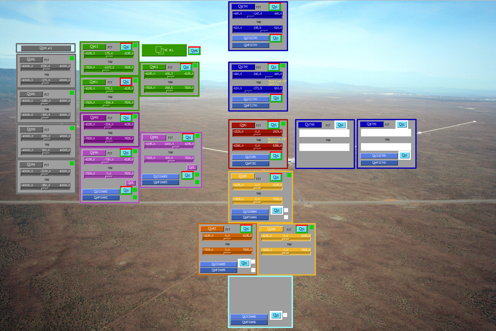
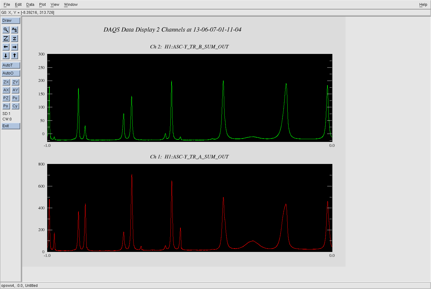
(Kiwamu, Chris, Stefan)

Morning:
========

Created the H1IFO_ALIGN medm screen and installed BS Face camera (with Richard)

Afternoon:
==========

First we re-established the IM4 trans reference that Keita established on May 22 (alog entry 6472). This was done my locking the IMC, moving the MC3 pitch slowly while input beam and MC were following, until we hit IM4 TRANS again. We then used the IMC WFS relief script (/opt/rtcds/userapps/release/ioo/h1/scripts/imc/mcwfsrelieve) to park the mode cleaner and input beam in this new orientation. (Note: this reliefs the offsets into the actuator offset fields, H1:IMC-MC1_PIT_OUTMON etc., NOT the MC alignment sliders (we should fix that tomorrow, see below for the current offsets)

Next, after thinking way too hard on how to proceed, we moved one slider (PR3 yaw, H1:SUS-PR3_M1_OPTICALIGN_Y_OFFSET) and saw the beam on the BS cage. Centering it roughly on the BS made it visible on the ITM cage.

The beam was moving too much, so we repeated yesterday's trick: increase the M0 damping gains... it worked again and quieted the beam motion down. (The old and new gains are below.)

With that we pointed the beam roughly on the middle of the ITM, and... saw fringes on both monitor and transmitted QPD. Since up to that point we had only moved one slider (H1:SUS-PR3_M1_OPTICALIGN_Y_OFFSET), nobody actually believed what we saw. But after misaligning the green beam the fringes were still there, and only went away when we moved the red beam...

Set up the anti-whitening filters for the transmission monitor at the end.

Next we wanted to go look for the green beam at ISCT1, but unfortunately the PLL loop broke (see Sheila's log). So that's for tomorrow.


Attached images:
===============
1) Alignment settings when we stared
2) Alignment settings after mode cleaner move (!Caution: additional nonzero MCWFS offsets, see below!)
3) Alignment setting when we got fringes (!Caution: additional nonzero MCWFS offsets, see below!)
4) Fringes on the trans mon!


Settings:
=========

Old PR2 and PR3 damping gains:
H1:SUS-PR2_M1_DAMP_L_GAIN = -1.55
H1:SUS-PR2_M1_DAMP_T_GAIN = -2
H1:SUS-PR2_M1_DAMP_V_GAIN = -3
H1:SUS-PR2_M1_DAMP_R_GAIN = -0.2
H1:SUS-PR2_M1_DAMP_P_GAIN = -2
H1:SUS-PR2_M1_DAMP_Y_GAIN = -1
H1:SUS-PR3_M1_DAMP_L_GAIN = -2
H1:SUS-PR3_M1_DAMP_T_GAIN = -5
H1:SUS-PR3_M1_DAMP_V_GAIN = -1
H1:SUS-PR3_M1_DAMP_R_GAIN = -0.02
H1:SUS-PR3_M1_DAMP_P_GAIN = -0.002
H1:SUS-PR3_M1_DAMP_Y_GAIN = -0.02

New PR2 and PR3 damping gains:
H1:SUS-PR2_M1_DAMP_L_GAIN = -15.5
H1:SUS-PR2_M1_DAMP_T_GAIN = -2
H1:SUS-PR2_M1_DAMP_V_GAIN = -3
H1:SUS-PR2_M1_DAMP_R_GAIN = -0.2
H1:SUS-PR2_M1_DAMP_P_GAIN = -2
H1:SUS-PR2_M1_DAMP_Y_GAIN = -1
H1:SUS-PR3_M1_DAMP_L_GAIN = -20
H1:SUS-PR3_M1_DAMP_T_GAIN = -5
H1:SUS-PR3_M1_DAMP_V_GAIN = -1
H1:SUS-PR3_M1_DAMP_R_GAIN = -0.02
H1:SUS-PR3_M1_DAMP_P_GAIN = -0.02
H1:SUS-PR3_M1_DAMP_Y_GAIN = -0.2

MCWFS offsets (those should be moved to the alignment sliders):
H1:IMC-MC1_PIT_OFFSET = 89.06
H1:IMC-MC2_PIT_OFFSET = 21.556
H1:IMC-MC3_PIT_OFFSET = 86.417
H1:IMC-PZT_PIT_OFFSET = 726.65
H1:IMC-MC1_YAW_OFFSET = 68.493
H1:IMC-MC2_YAW_OFFSET = 4.6945
H1:IMC-MC3_YAW_OFFSET = -69.693
H1:IMC-PZT_YAW_OFFSET = 4073.9
Images attached to this report


Comments related to this report
Forgot to mention the obvious: Hats off to the initial alignment team!
