travis.sadecki@LIGO.ORG - posted 11:59, Tuesday 09 July 2024 (78963)
MX and EX Turbo functionality test
Jennie, Jenne, Sheila, Keita
While the PSL team were preparing for a PSL in cursion, I started moving MC3 based on our plan to re-align onto the ISS array and IM4 TRANS QPD after the PMC swap last week.
We tried going up in yaw, saw some increase in power on IM4 trans QPD but then the ISS second loop QPD started to become further from the centre position as did the IM4_TRANS QPD (this is well centred enough that we could see the power drop whereas the ISS QPD started quite far off centre so that the nsum is quite close to zero).
We went back to the maximum value then tried IM3 alignment is both DOFs but this did not improve things in both QPDs so we tried MC3 pitch. Sheila then noticed that we were mazking the IMC relflected spot some horrible higher order mode so we decided to stop and think.
MC1 and MC3 changed in common yaw due to the WFS as we changed the uncorntolled differential DOF (MC1 - MC3), which we did not expect, to recover our alignment we would need MC1 and MC3 to change differentially as they did after the PMC swap, in this image.
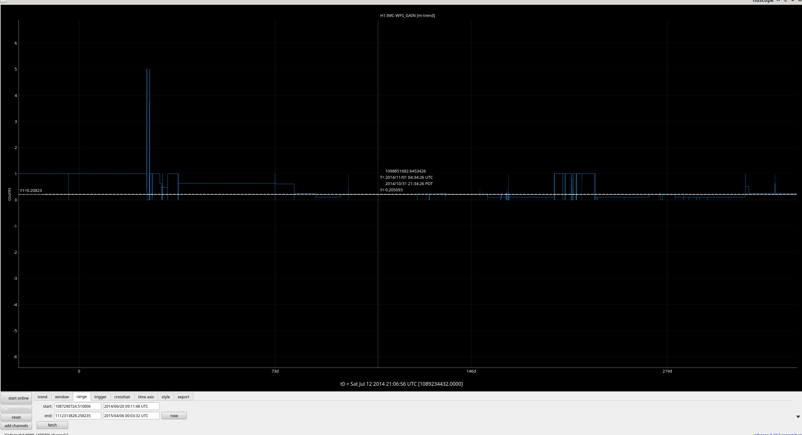
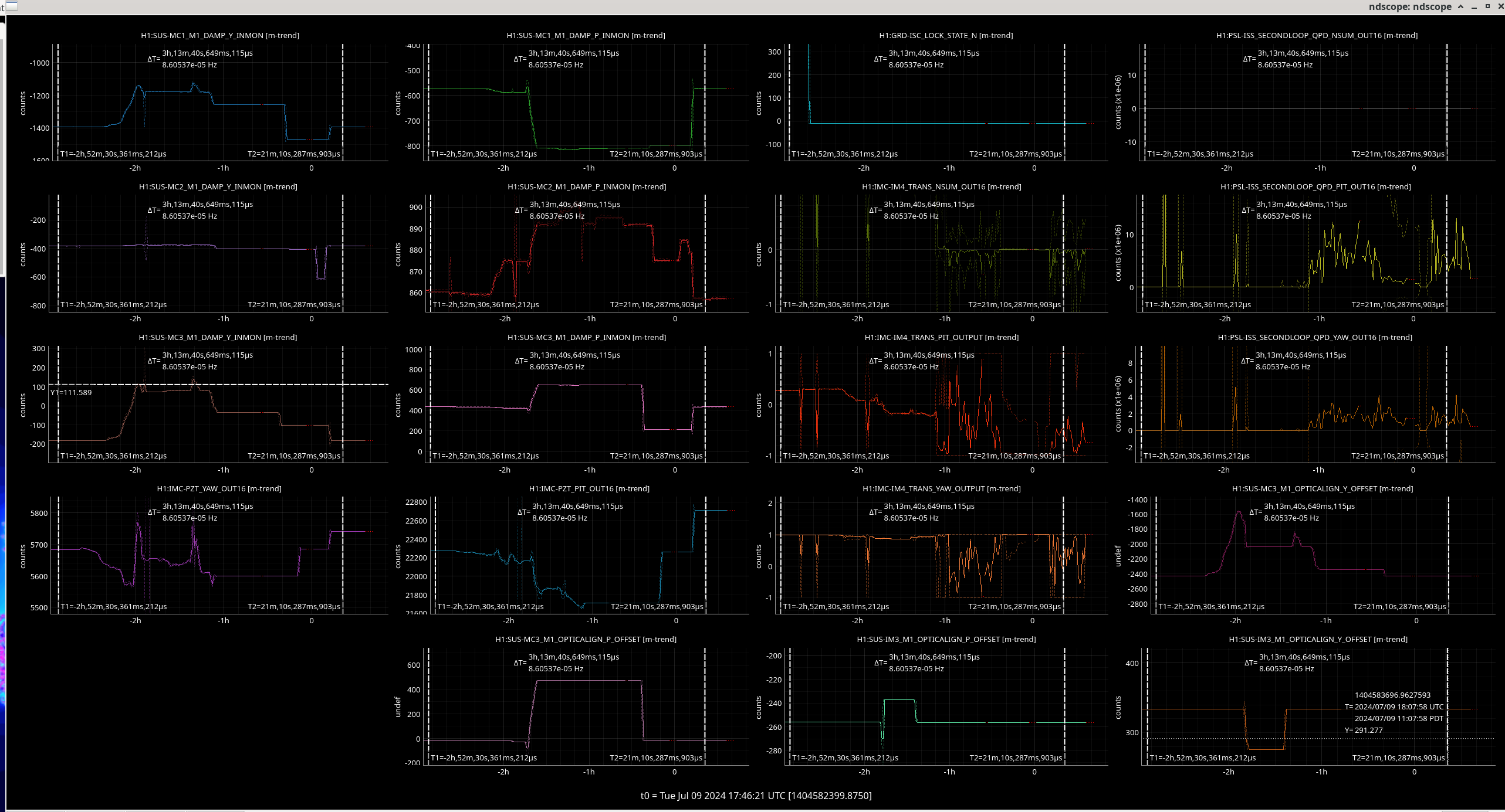
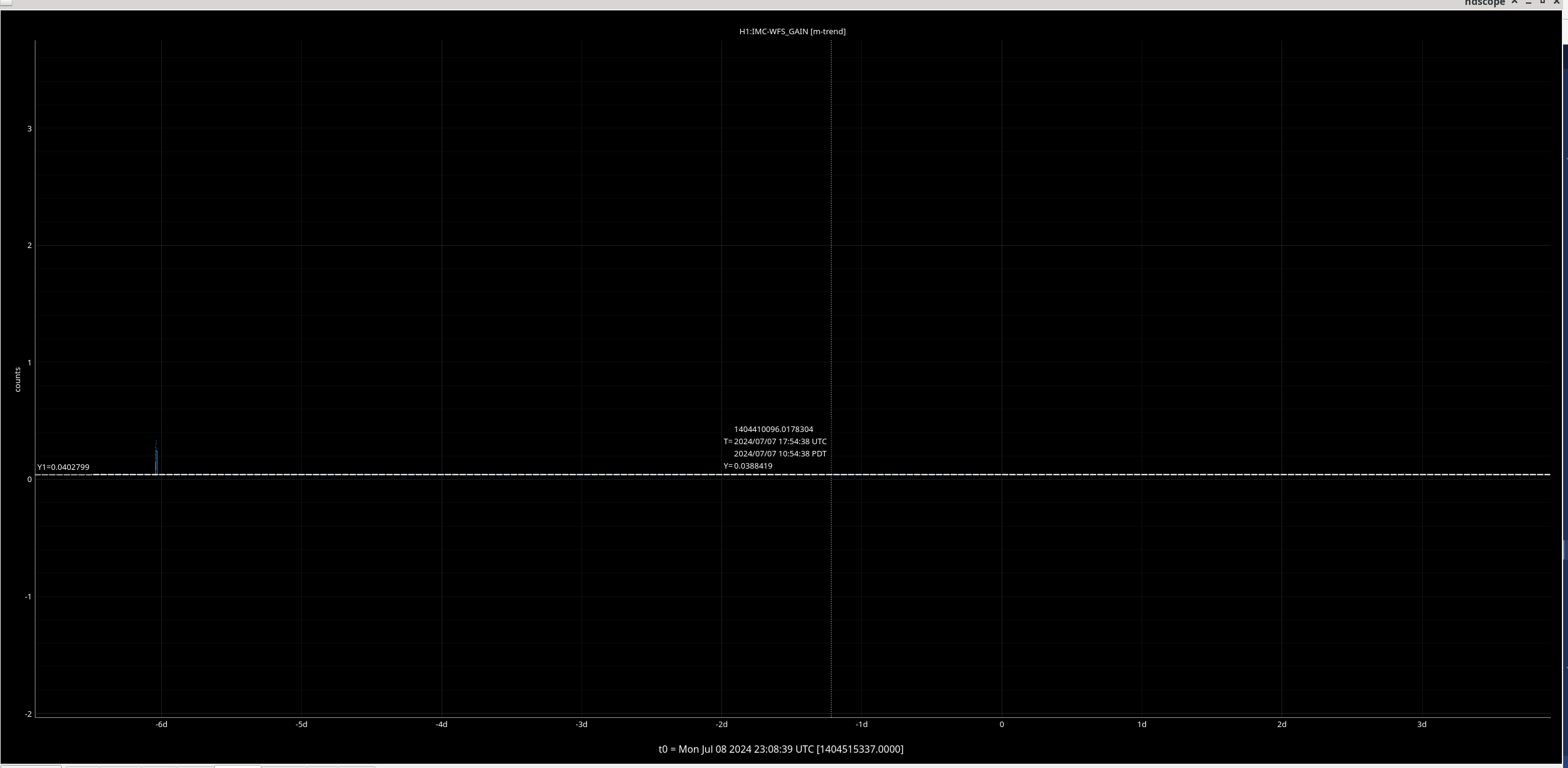
The ndscope channels I used for this alignment walking session are attached with cusors before we changed anything and after we recovered the IMC alignment to pre-maintenance.
In conclusion we have reverted the IMC alignment back to before our changes as we think some action before the in-vacuum mirrors is needed.
Plan: To revert periscope PZT and MC1 back to their positions before the PMC swap and get Jason/Ryan to move steering mirrors in the PCAL enclosure to recover the prompt reflection from the IMC as witnessed by the MC WFS behind MC1. Then we can re-align the IMC.

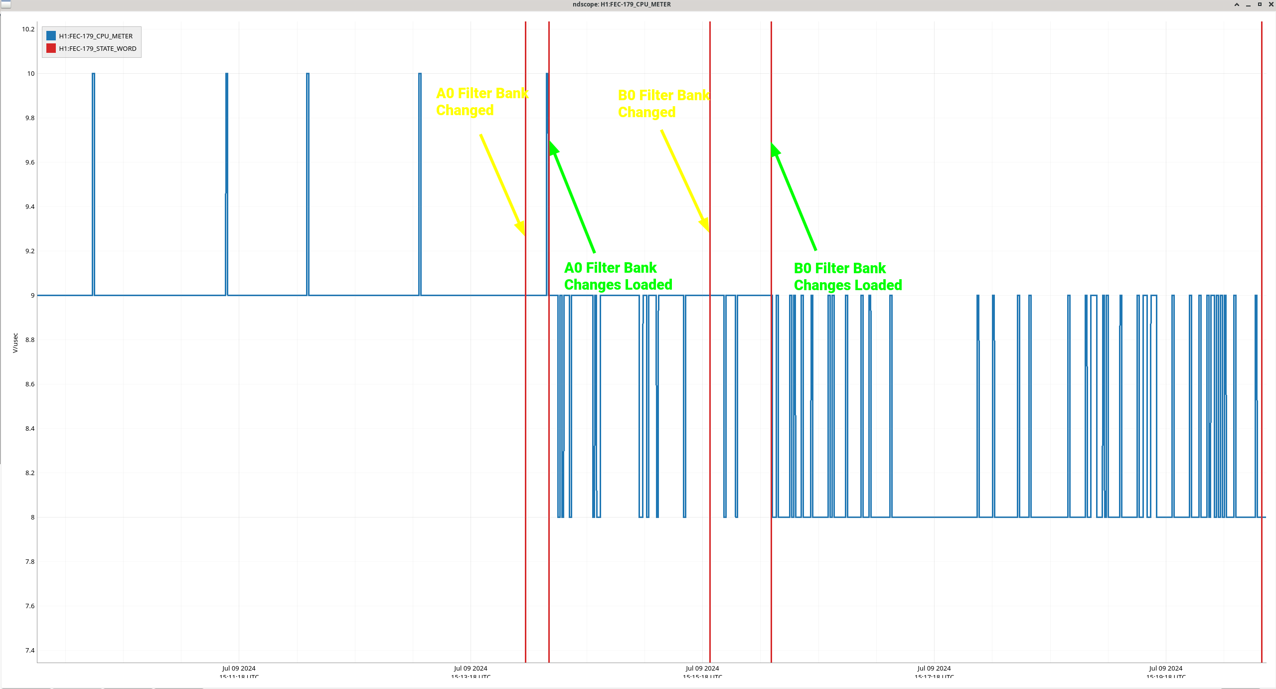
J. Kissel, D. Barker, E. von Reis
WP 11969

The h1iopomc0 model changes I prepped this morning LHO:78956 have been installed.

Further, one at at time, I've installed copies of the primary OMC DCPD A0 and B0 filter bank filters into the A1, A2, and B1, B2 filters in order to test the consumption of computational turn around time (see preliminary discussions in LHO:78958). Finally, I've added a reasonably high-order high-pass filter into the A1 and B1 banks to test whether we can add even *more* filters enough to accomplish the tests discussed in LHO:78956.

Attached is an annotated time series of the CPU meter channel (H1:FEC-179_CPU_METER) as each of these things happened.

In short -- even with new the filters "fully loaded," the model computational turn around time runs at 12 [usec], occasionally popping up to 13 [usec] -- under the ideal limit of 15.3 [usec].
In addition, we don't see any IPC timing errors in either the OMC user model or the end station PI models that are receiving IPC from the h1iopomc0 model.

So, we'll leave this diagnostic infrastructure in place for a few weeks, until we decide we don't need it anymore.

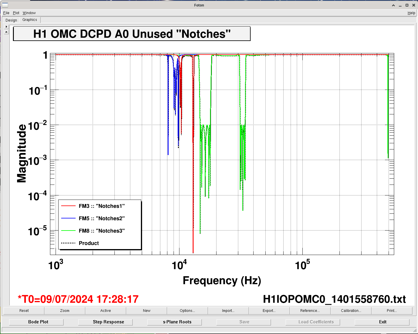
J. Kissel, E. von Reis, D. Sigg

Circa March 2023, Daniel had installed some never-used first attempts at further filtering the high frequency noise present in the 524 kHz OMC DCPD channels (never aLOGged because it was never used, but I call them out after I found the work in LHO:68098).

Now, because I'd like to characterize the existing, in-use, digital AA filtering, running into some unknown noise (LHO:78516), and hoping to install 2 to 4 more parallel filter banks that would also be quite full of filters (LHO:78956), there is worry that there won't be enough computation time in the 524 kHz system.

Remember, that "the 524 kHz system" is actually a modified "standard" 65 kHz system, which is reading out 8 samples from the 524 kHz ADC each 65 kHz clock cycle and computing everything at 65 kHz. Thus, in principle, the max turn around time is
    1 / (2^16 Hz) = (1 / 65536) [sec] = 1.5258789e-5 [sec] = 15.3 [usec]

However, we *think* the practical limit is somewhat less that this. I don't think I understand what those limitations are enough to say definitively and/or to quote a limit quantitatively, but I think they're related to "the copy of the OMC DCPD channels which are demodulated at high frequency to create PI channels that are shipped to the end station -- in other words, the IPC sending demands a bit of computational time, and if there isn't enough turnaround time left in the OP to write to the IPC network, then the end-station SUS PI models throw an IPC timing error."

Anyways -- this morning, I looked at the 524 kHz system's computation time as is before doing anything (via the channel H1:FEC-179_CPU_METER), and it's sitting at 9 [usec] (out of the ideal 15 [usec]), occasionally popping up to 10 [usec].

But -- this led me to remember that -- regardless of whether the filter is turned ON -- the front-end computes the output of the filter -- sucking up computation time.
So, I've removed these unused prototype notch filters from the DCPD A0 and B0 filter banks.
In addition, I've also removed the old "V2A" filter from a previous version of the digital compensation for the OMC DCPD transimpedance amplifier response.

Removing the notch filters drops the computation time from "9 [sec] occasionally bopping up to 10 [usec]."
See attached time series of the CPU meter.

These filters are, of course, available in the filter_archive, under the latest previous archived file before today's work:
    /opt/rtcds/lho/h1/chans/filter_archive/h1iopomc0/
        H1IOPOMC0_1401558760.txt
but for ease of use, I copy them here.

FM3 :: Notches1
    ellip("BandStop",3,0.5,30,12800,13200)
    notch(10216,50,30)
    ellip("BandStop",3,0.5,30,10380,10465)
    ellip("BandStop",3,0.5,30,12900,13100)

FM5 :: Notches2
    ellip("BandStop",3,0.5,30,8100,8200)
    notch(9101,50,30)notch(9337,200,30)
    notch(9463,50,20)
    ellip("BandStop",3,0.5,30,9750,9950)

FM8 :: Notches3
    ellip("BandStop",5,0.5,40,14384,18384)
    ellip("BandStop",5,0.5,40,30768,34768)

FM6 :: V2A
    zpk([5.699+i*22.223;5.699-i*22.223;32.73],[2.549;2.117;6.555],0.00501187,"n")gain(0.971763)
I've also posted a plot of the magnitude of these notch filters -- mostly just to demonstrate how many second order sections that these filters had -- sucking up computation time.


Keita, Sheila
We were looking for explanations for the drops in range we've seen since Tuesday. Attached is a plot of the CPU meter, it seems that this jumped up shortly after Jeff's plot was made. It is still below 13usec, and doesn't look correlated with our range problems.
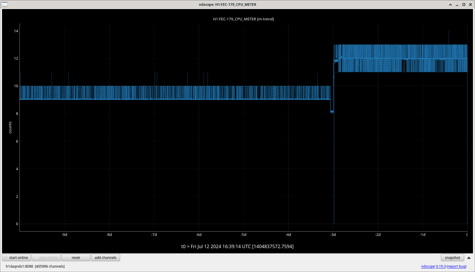
Variation of CPU time in that range shouldn't by itself have any effect on the control loops running on that model until they get to a sustained time above 15 us or an individual cycle time somewhat more than 15 us depending on the model.
The effects of a model that's run too long are DAC buffer starvation, i.e. the IOP didn't keep up with the DAC clocks, or IPC communication between models arriving to late.
Both of these errors would appear immediately on the CDS overview MEDM.
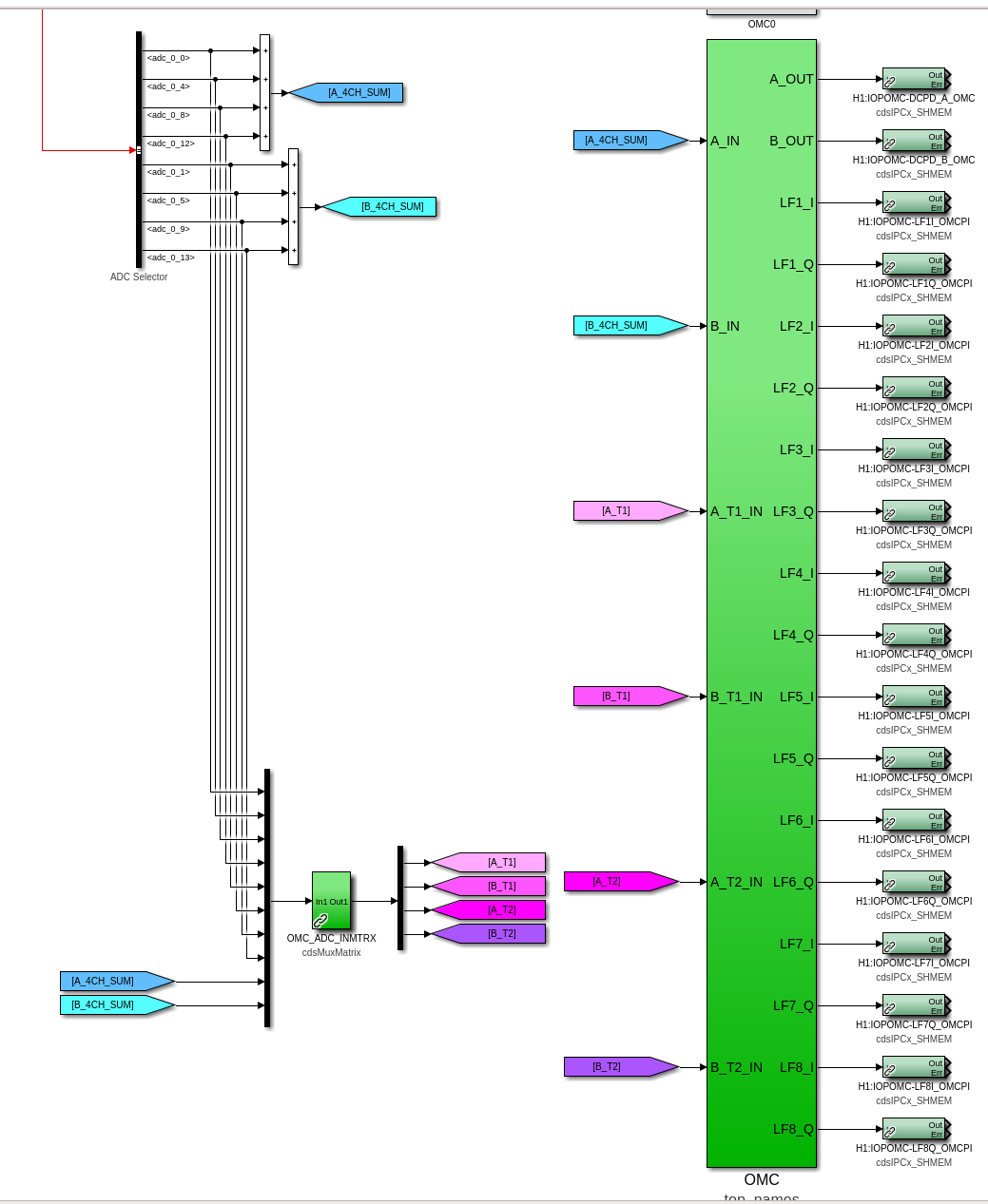
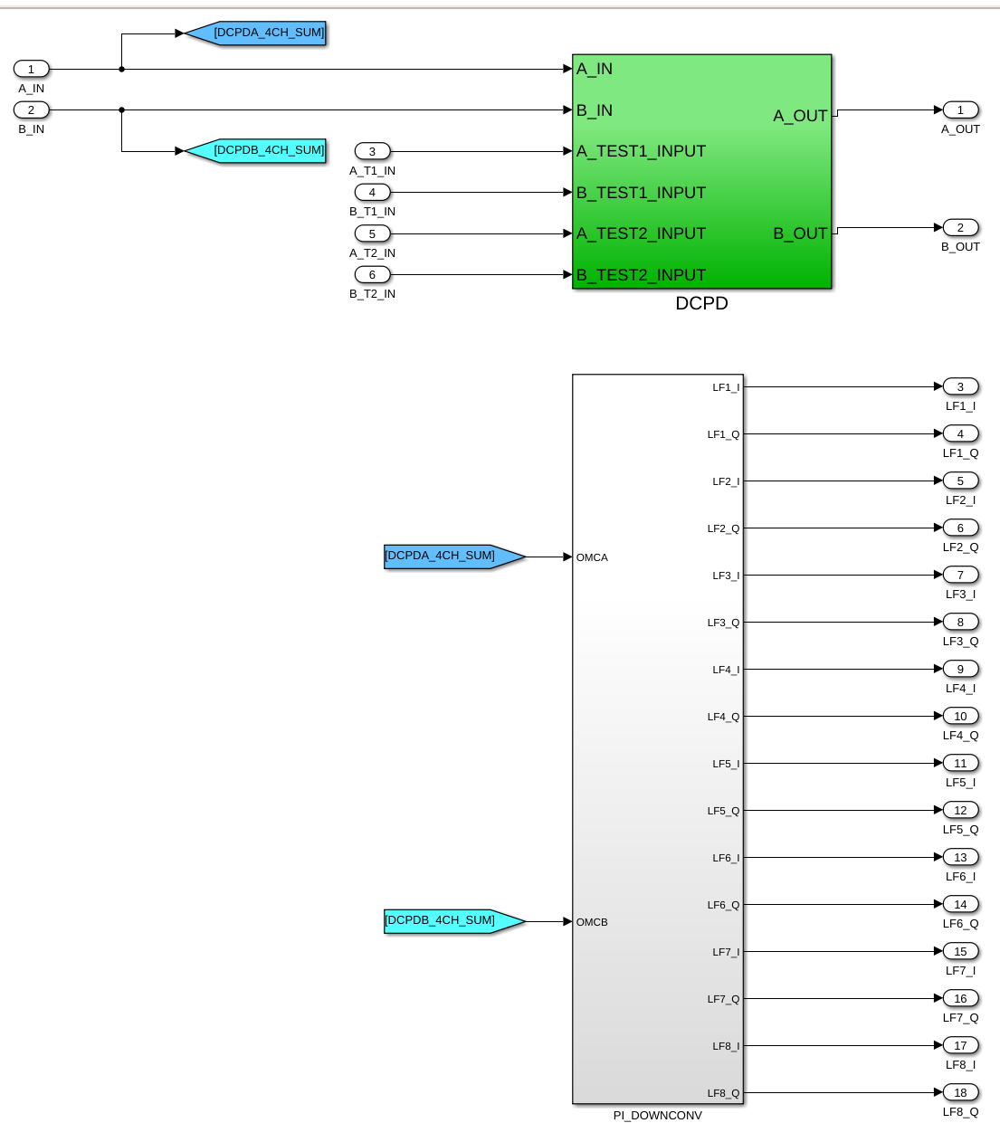
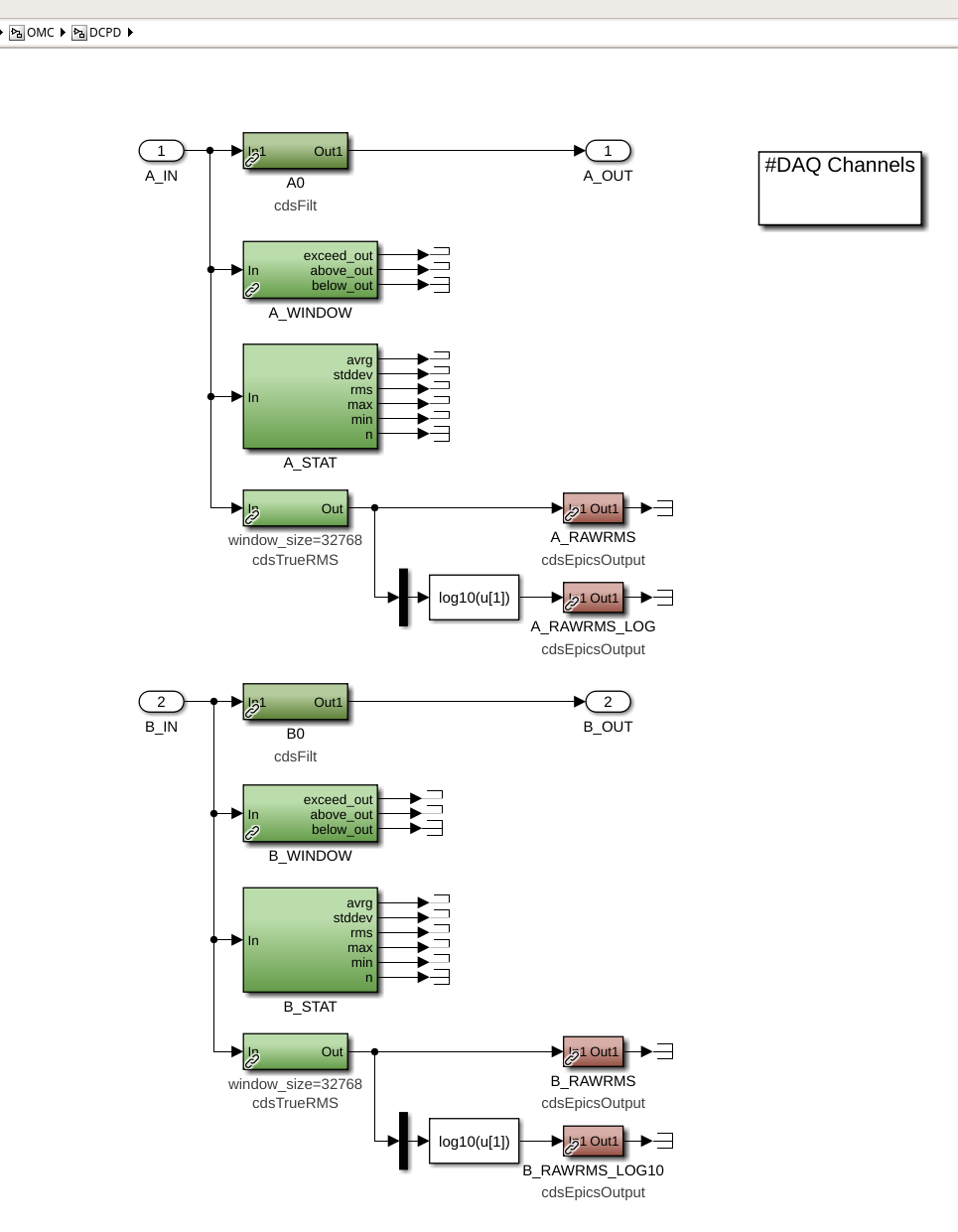
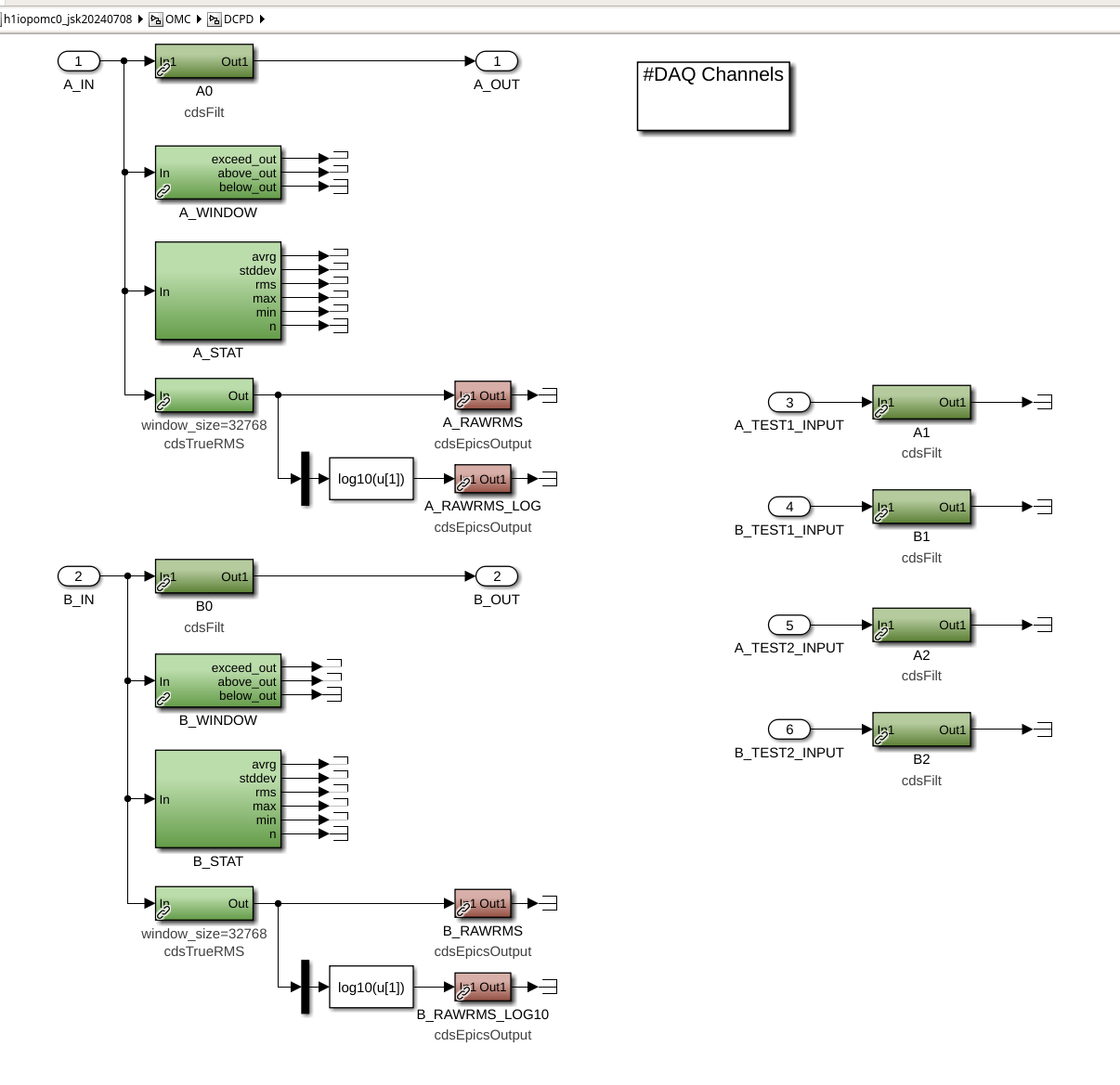
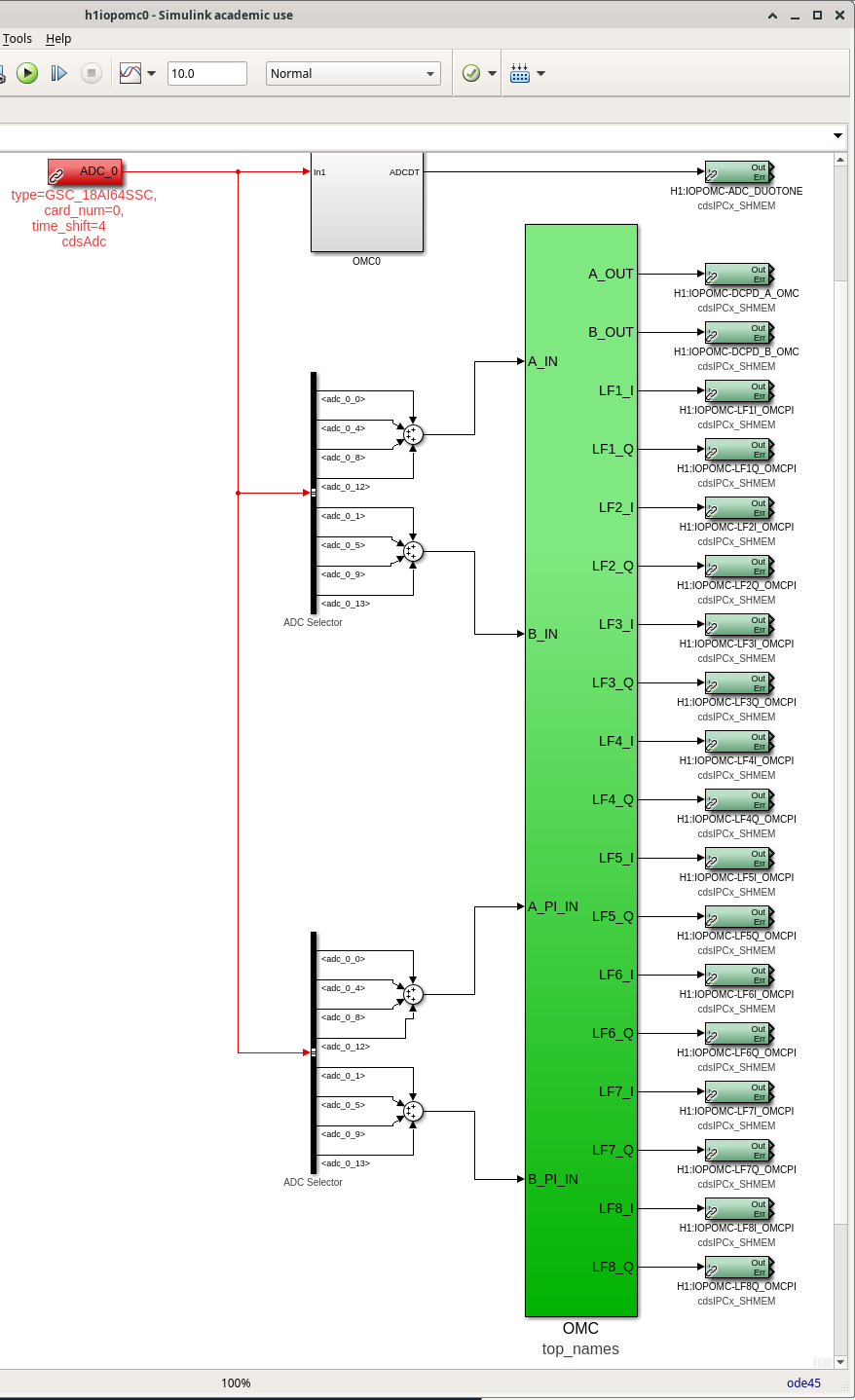
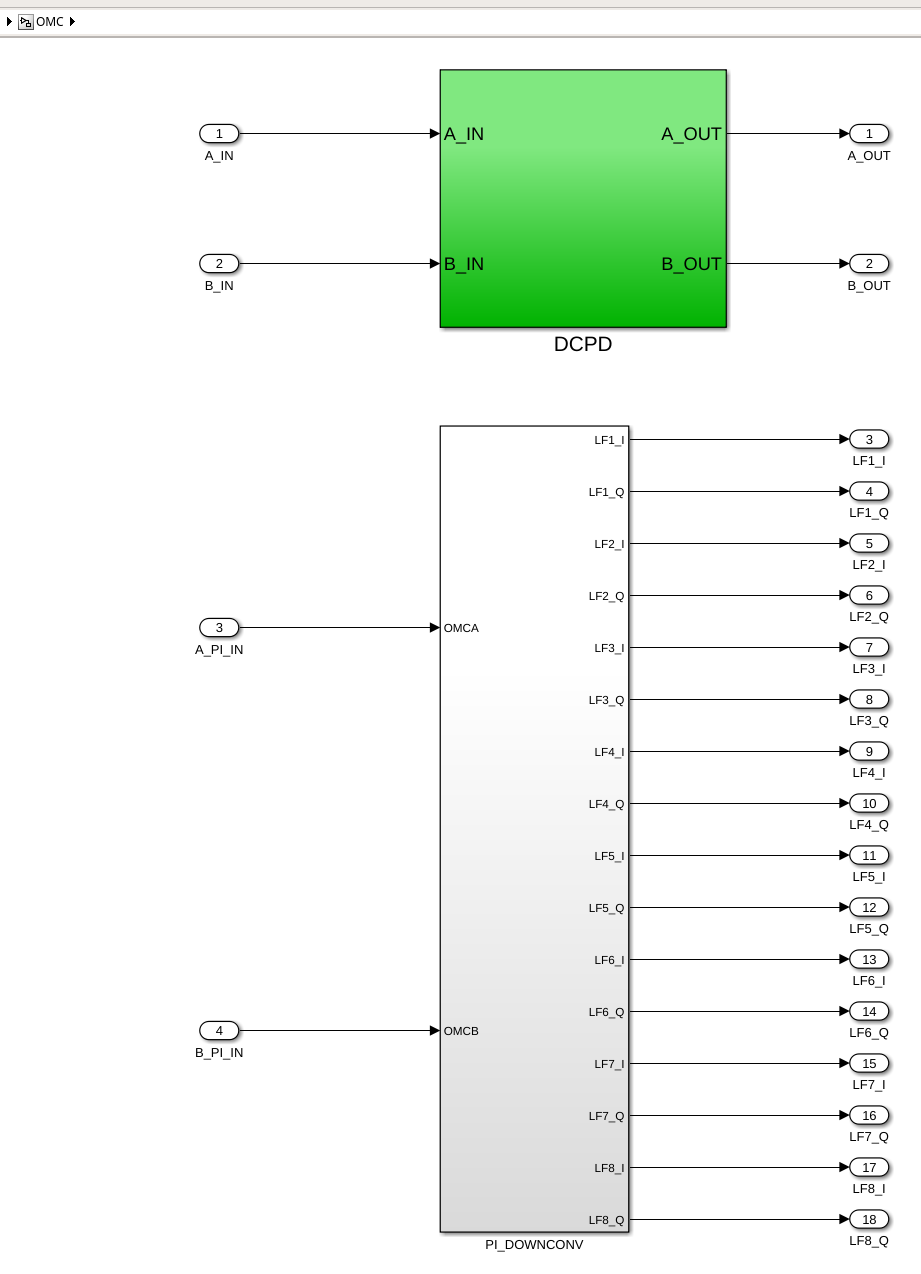
J. Kissel, with help from E. von Reis, D. Barker, D. Sigg
WP 11969

Continuing investigations of high frequency limitations of characterizing the anti-aliasing processing performance for the 524 kHz OMC DCPD system (LHO:78516), there are a few unconfirmed suspicions about whether the flat noise "limit" above ~20 kHz -- seen in only in the NOMINAL_LOW_NOISE data -- is ADC noise or numerical precision issues. There are two suggested measurements that would confirm one or the other empirically:
   (1) "Compare the high frequency noise of 4 channel sum / average against the noise in a single channel"
        If the noise changes by sqrt(4) = 2 (with the underlying assumption that the noise of the ADC is identical for each channel), then the noise floor is ADC noise not precision limit.
   (2) "High pass the data in the real-time to remove the large DC component"
        If the low frequency DC signal is removed in the real time system -- which is running at 32-bit double precision, and *then* we compute the ASD via a grabbing the data once turned into a test point (which is done at single precision) -- then the ASD should *not* be limited by the single precision noise floor.

However, the current infrastructure doesn't support either tests.
   For (1), while we do have access to the the ADC channels are summed immediately off the ADC as test points (i.e. H1:IOP-OMC0_MADC0_CH[0,4,8,12]), they're not piped into any filter banks, so we can't make any of the high-dynamic-range testing of the Digital AA filtering comparisons with the output of the primary DCPD banks.
   For (2), these are the gravitational wave channels, and the in-loop DARM loop error signals. "Just toss in a high-pass" is not an option (the DARM loop would go unstable and/or at least lose a bunch of low frequency gain; if if the IFO would funciton it would mean drastic impact on the calibration of the detector).

As such, I'm document here the front-end model changes I hope to install that creates pick-off paths for the eight ADC channels (four copies of the voltage from DCPD A and four for DCPD B), piping them in to an ADC_INMTRX matrix (along with the 4 channel sum) for a total of 10 inputs, and then piping that output of that matrix into 4 filter banks whose output is terminated. The design intent is for these filter banks to mostly contain exact copies of the primary DCPD_A0 and B0 filter banks, but we're free to modify them and play around with, say, adding a high pass, whenever we want without consequences for the detector. I'm also a big fan of "clean as you go," so I've also taken the opportunity to make the simulink diagram a (little cleaner / legible / less redundant) for the primary existing paths.

Attached are screenshots showing the model changes:
    - Top level before vs. after
        Comparing these two, you see immediately the new input matrix. But also, you see that the PI path is now no longer a equal parallel copy of the sum of the channels, but instead the sum is done once, and the output of the sum is fed into the OMC block to be split out in there.
    - One layer down, into the top_named OMC block, before vs. after
        Here is where the OMC DCPD 4 channel sum is picked off for the PI path with a goto tag, rather than re-computing the sum. The new matrix output channels are fed into the DCPD block.
    - A further layer deeper, into the OMC_DCPD block, before vs. after
        Here the new matrix output channels are fed into 4 filter banks.

At the moment, we're unsure whether the 524 kHz system can handle this many more filter banks without running out of computation time to ship the PI data to the end stations. So we may end up reducing the amount of test filters from 4 to 2. Further, once we gather enough data, there may be a chance that we no longer need these test pickoff filters. Thus, at the moment, this a "prototype" change, with work permit only, and not an ECR -- since it may not be needed for more that a week or two.


Link to report
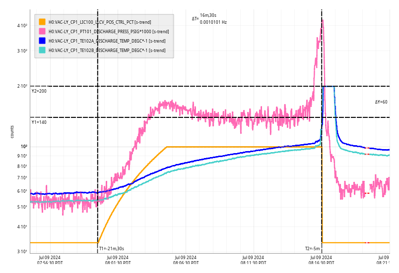
Tue Jul 09 08:16:30 2024 INFO: Fill completed in 16min 25secs
Jordan confirmed a good fill curbside.
TITLE: 07/09 Day Shift: 1430-2330 UTC (0730-1630 PST), all times posted in UTC
STATE of H1: Observing at 157Mpc
OUTGOING OPERATOR: Tony
CURRENT ENVIRONMENT:
SEI_ENV state: CALM
Wind: 4mph Gusts, 2mph 5min avg
Primary useism: 0.01 μm/s
Secondary useism: 0.04 μm/s
QUICK SUMMARY: Locked for 6.5 hours. PEM_MAG_INJ node is in error, I'll wait to fix it so it dont start to conflict with the charge measurements. Maintenance day today.
Workstations were updated and rebooted. This was an OS package update. Conda packages were not updated.
TITLE: 07/09 Eve Shift: 2300-0800 UTC (1600-0100 PST), all times posted in UTC
STATE of H1: Lock Acquisition
INCOMING OPERATOR: Tony
SHIFT SUMMARY: Relocking and currently in INJECT_SQUEEZING, and weirdly we had been stuck in LASER_NOISE_SUPPRESSION for over 10 minutes. It looks like IMC_LOCK stalled in OPEN_ISS and was just sitting there. I reselected ISS_ON and it eventually arrived there and we were able to move on to ADS_TO_CAMERAS
Had some trouble getting DRMI to lock this last lockloss and it ended up going through PRMI, even after an initial alignment and then a partial initial alignment where I just did PRC, MICH, and SRC. Other than that, relocking has been smooth. I didn't get a chance to look into the two locklosses that happened during my shift, but I know they weren't caused by wind or ground motion.
LOG:
23:00 Detector Observing at 155Mpc and has been Locked for almost 6 hours
01:46 Lockloss
02:55 NOMINAL_LOW_NOISE
02:57 Observing
05:52 Lockloss
- I started an initial alignment
- While INIT_ALIGN was trying to lock ALSY we had EY and TMSY saturations
06:16 IA done, relocking
06:30 Lockloss from ACQUIRE_DRMI_1F (possible that it was due to me moving BS?)
06:37 Lockloss from ACQUIRE_DRMI_1F
06:37 I took us to manual initial alignment so I could align PRC, MICH and SRC in case I had misaligned them?
06:49 Partial IA done, trying relocking again
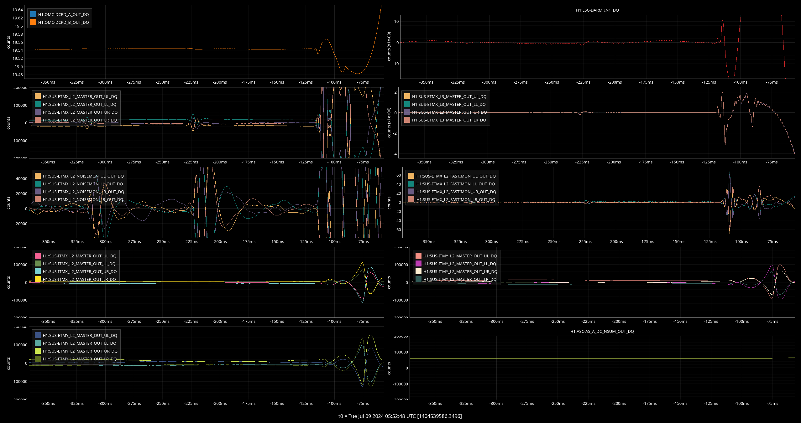
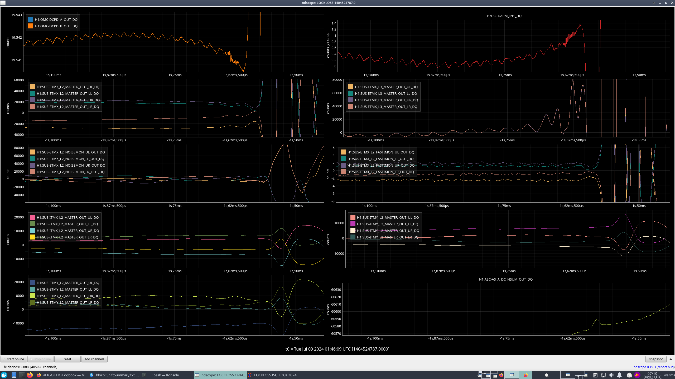
More odd ETMX moves ~200ms before lock loss.
Currently Observing at 156Mpc and have been locked for just over an hour. Relocking after the 07/09 01:46UTC lockloss (78947) wasn't too bad - I didn't need to do an initial alignment and just needed to help PRMI and DRMI lock by hand.
Lockloss @ 07/09 01:46UTC after 8.5 hours locked
02:57 UTC Observing
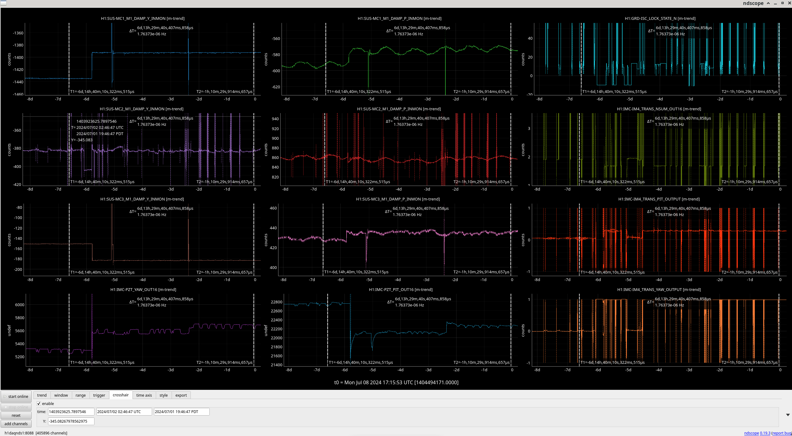
Jennie W, Jenne, Keita, Sheila
Summary: The input alignment was changed due to the PMC (pre-mode cleaner) swap last week. Sheila et. al. tried to recover this with IM3 moves but the IM4 TRANS QPD, our main alignment reference into the main IFO, is still off in yaw and so we will need to walk mirror or mirrors in the IMC (input mode cleaner) tomorrow to recover this.
The other option is to move something upstream in the PSL but this is harder to do as it involves moving in air steering mirrors and so is harder to reverse. This is plan B for another maintenance Tuesday.
Attached you can see how the MC mirrors changed before (first cursor) and after (second cursor) the PMC swap and Jenne tweaking the periscope mirror (first two plots in bottom row show positioning into IMC via the pitch and yaw of the upper PSL periscope mirror).
Plan: Move MC3 in yaw in order to change the output spot position in the IMC. We will do this with the ASC for the IMC running so the alignment loops for the angle of MC2 and the differential yaw between MC1 and MC3 will still run, but I will increase the gain value of these loops to its old value from December 2014 (0.25).
For future reference, the triangular cavity DOFs are discussed here: DCC LIGO-P1000135
And the MC in particular here: DCC LIGO-G1301131


TITLE: 07/08 Day Shift: 1430-2330 UTC (0730-1630 PST), all times posted in UTC
STATE of H1: Observing at 155Mpc
INCOMING OPERATOR: Oli
SHIFT SUMMARY:
Internet went down 15:09 UTC for what seemed like less than a minute. Cause: Automatic Switching from Boise Connection to Seattle.
Lockloss 15:11 UTC due to an earthquake.
https://ldas-jobs.ligo-wa.caltech.edu/~lockloss/index.cgi?event=1404486684
We moved PR3 back to it's previous position while in Input_Align.
Sheila is touching up the COMM And DIFF beat notes.
17:14 UTC Earthquake passed through and was not announced.
Comissioning started at 17:16 UTC
Nominal_Low_Noise reached at 18:31 UTC.
Observing reached at 18:32 UTC
LOG:
| Start Time | System | Name | Location | Lazer_Haz | Task | Time End |
|---|---|---|---|---|---|---|
| 16:08 | SAF | LVEA | LVEA | YES | LVEA IS LASER HAZARD | 10:08 |
| 15:02 | FAC | Tyler | Water Tank | N | Moving truck over to water tank | 15:12 |
| 15:28 | FAC | Karen | Optics Lab & VAC Prep | N | Technical Cleaning | 15:57 |
| 15:59 | ISC | Sheila | ICST1 | Yes | Aligning COMM and DIFF BeatNotes | 16:29 |
| 16:45 | FAC | Karen | Mid Y | N | Technical Cleaning | 17:45 |
| 16:53 | FAC | Kim | Mid X | N | Technical Cleaning | 17:42 |
| 17:26 | SQZ | Naoki | Ctrl Rm | N | Testing SQZr | 17:46 |
| 17:55 | PCAL | Francisco | PCAL Lab | Yes | PCAL Lab Upgrades | 20:59 |
| 18:12 | PRCL | Camilla | CRTL Rm | N | PRCL Measurement | 18:22 |
| 18:20 | OMC | Naoki | Ctrl Rm | N | Exciting OMC | 18:24 |
| 18:25 | SUS | Josh | Ctrl Rm | N | osem measurements | 18:30 |
TITLE: 07/08 Eve Shift: 2300-0800 UTC (1600-0100 PST), all times posted in UTC
STATE of H1: Observing at 154Mpc
OUTGOING OPERATOR: Tony
CURRENT ENVIRONMENT:
SEI_ENV state: CALM
Wind: 9mph Gusts, 4mph 5min avg
Primary useism: 0.02 μm/s
Secondary useism: 0.05 μm/s
QUICK SUMMARY:
Observing and Locked for almost 6 hours. Everything going well.
DriptaB, FranciscoL
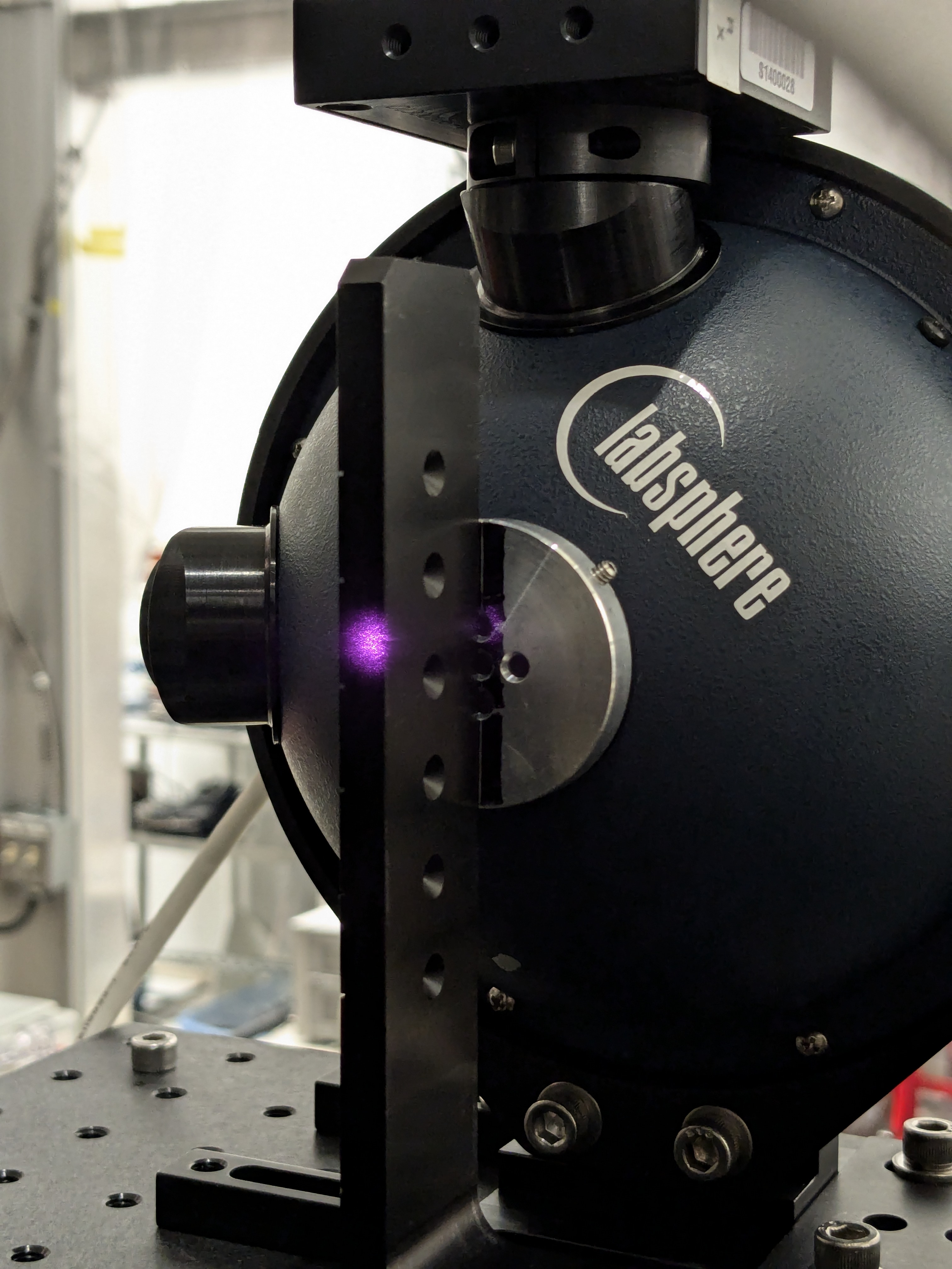
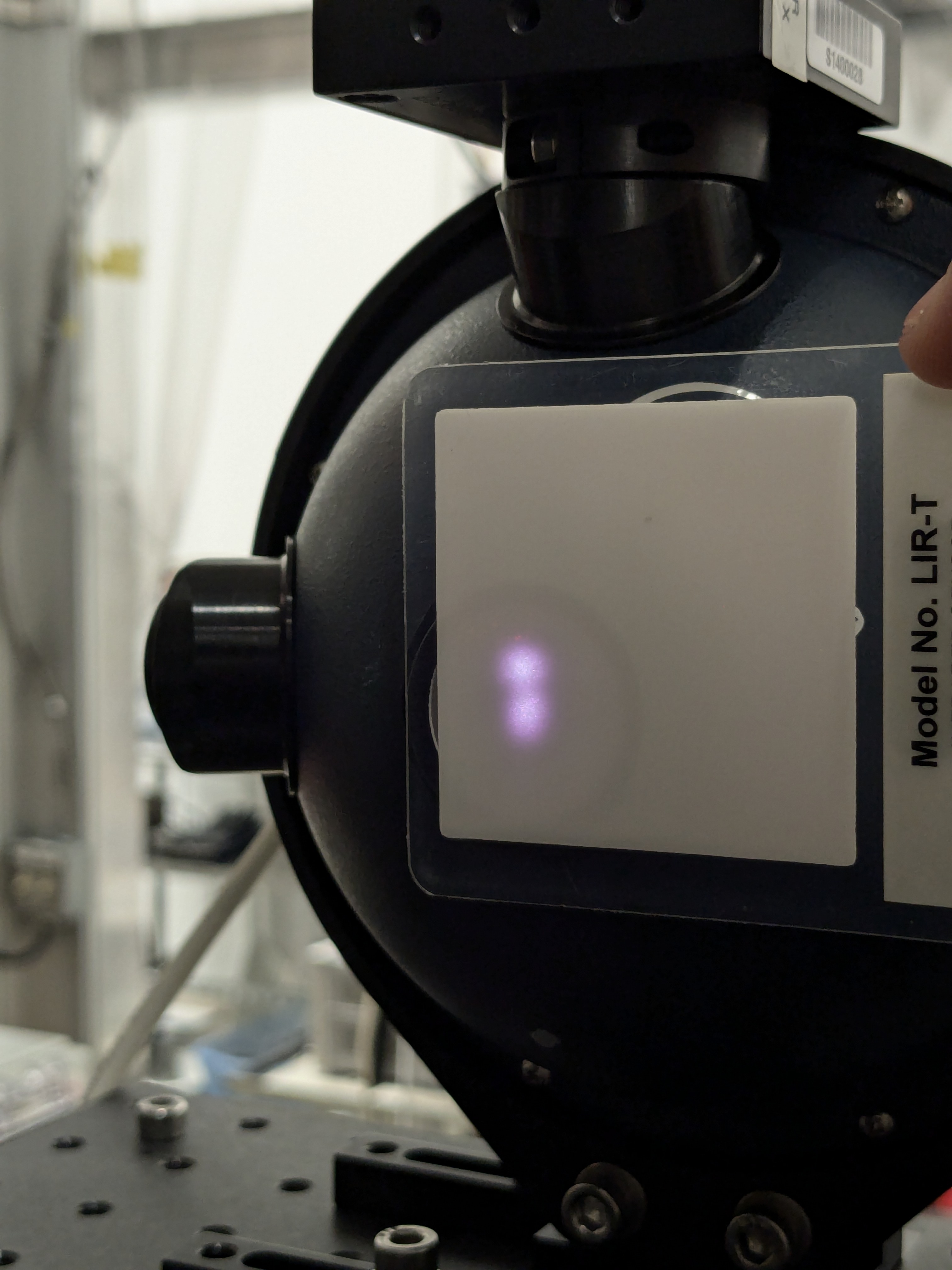
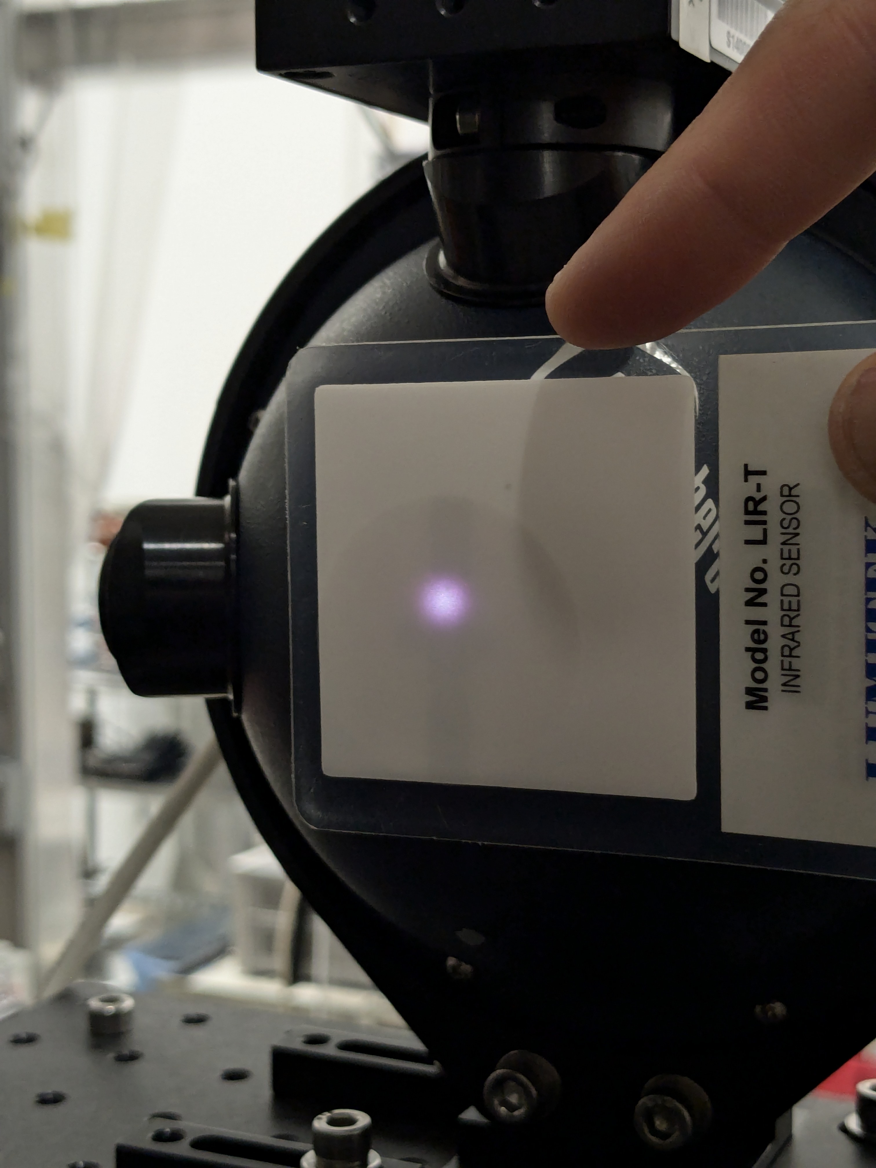
After one week of having the inner beam up on the Rx sensor (alog 78807), on July 2, we moved the beam from up to center.
The last page of EndStationLog.pdf lists the voltage values after each significant step of procedure T2400163. The steps represent writing down a voltage value after a particular change to the beam position. Some highlights from the recorded values:
The 'Initial' measurement is *equal* to the last voltage measurement from the previous movement, done on June 25 (alog 78807). The initial and final voltage measurement during today procedure did not change.
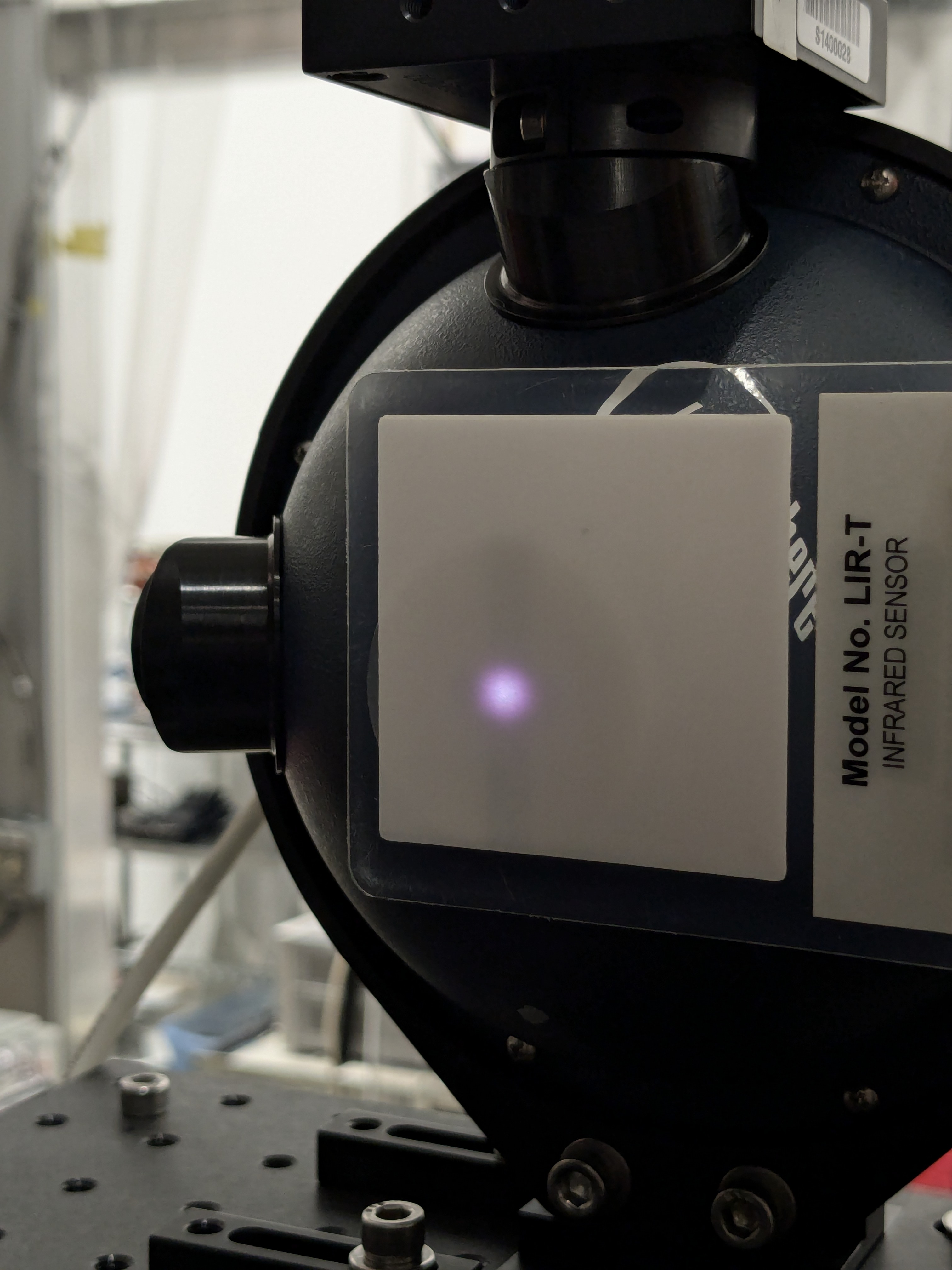
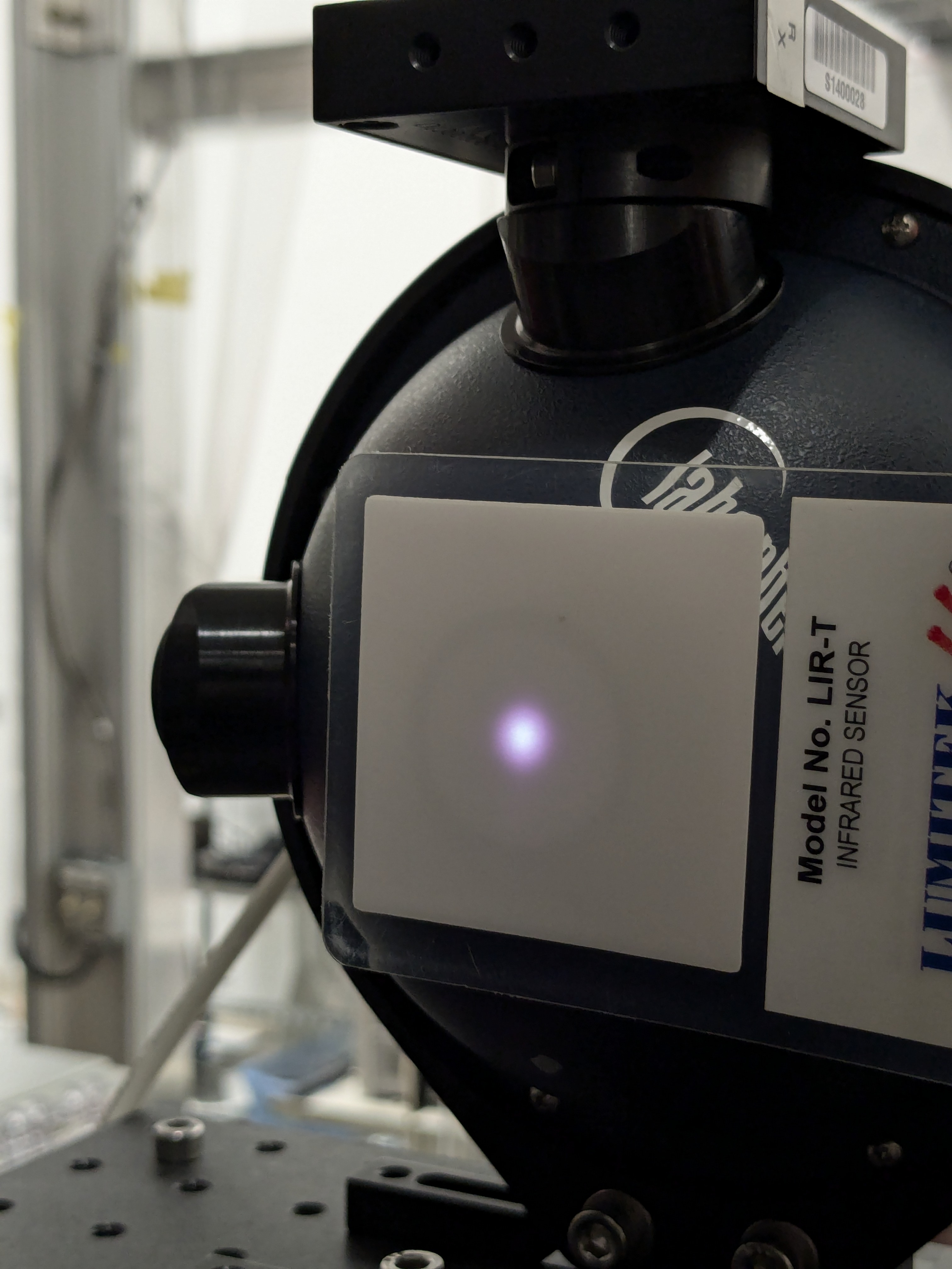
Title should be "eight", not "seventh". This movement was a week after the seventh move, which was moved up (alog 78807).
State of H1: Observing at 157Mpc, locked for 6.5 hours.
Quiet shift so far except for another errant Picket Fence trigger to EQ mode just like ones seen last night (alog78404) at 02:42 UTC (tagging SEI).
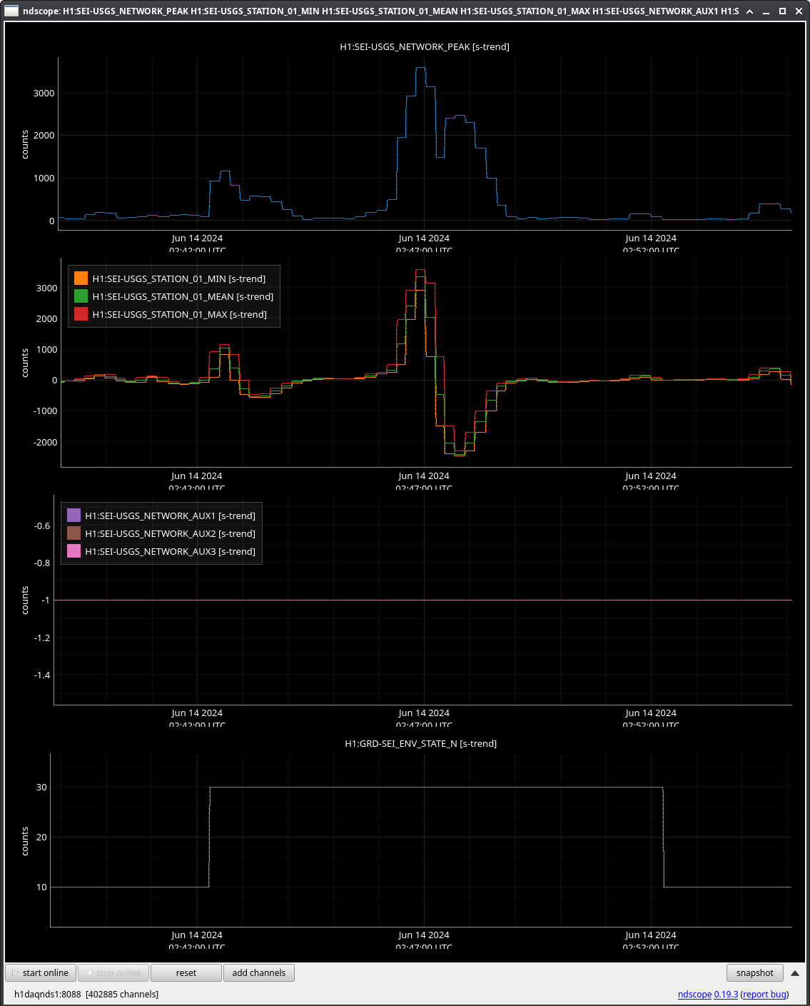
That's about two triggers in a short time. If the false triggers are an issue, we should consider triggering on picket fence only if there's a Seismon alert.
The picket fence-only transition was commented out last weekend on the 15th by Oli. We now will only transition on picket fence signals if there is a live seismon notificaition.
Thanks Jim,
I'm back from my vacation and will resume work on the picket fence to see if we can fix these errant triggers this summer.
