So, the afternoon BS FC application/removal indeed picked up the hazy 3" circle at the 3 o'clock position and the FC remnants at the center of the optic. However, there are now little "splatter dots" across the ~entire surface, 1-3 every inch. Some are a little circle like feature, as if we "sprayed something wet on it" and it dried in small dots - ha. So, I'm certain these are from the FC spray drying faster than I could spray - even when I was anticipating this and sprayed fast to try to avoid this. Possibly a subsequent FC cleaning could remove these, but I'm out of time to keep performing this few hour long task again and again. Will confer with CIT regarding cleaning in 2 months.
Arnaud and Travis finished reassembling the BS EQ stops and ellipt baffle and took B & K measurements, so we are done there.
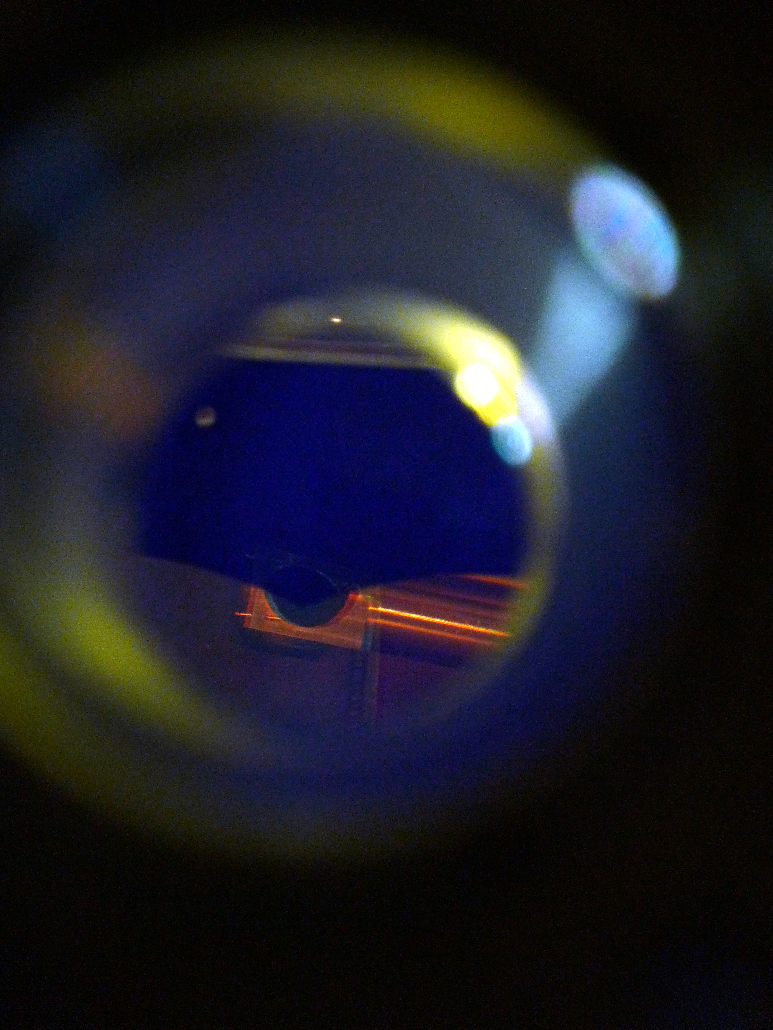
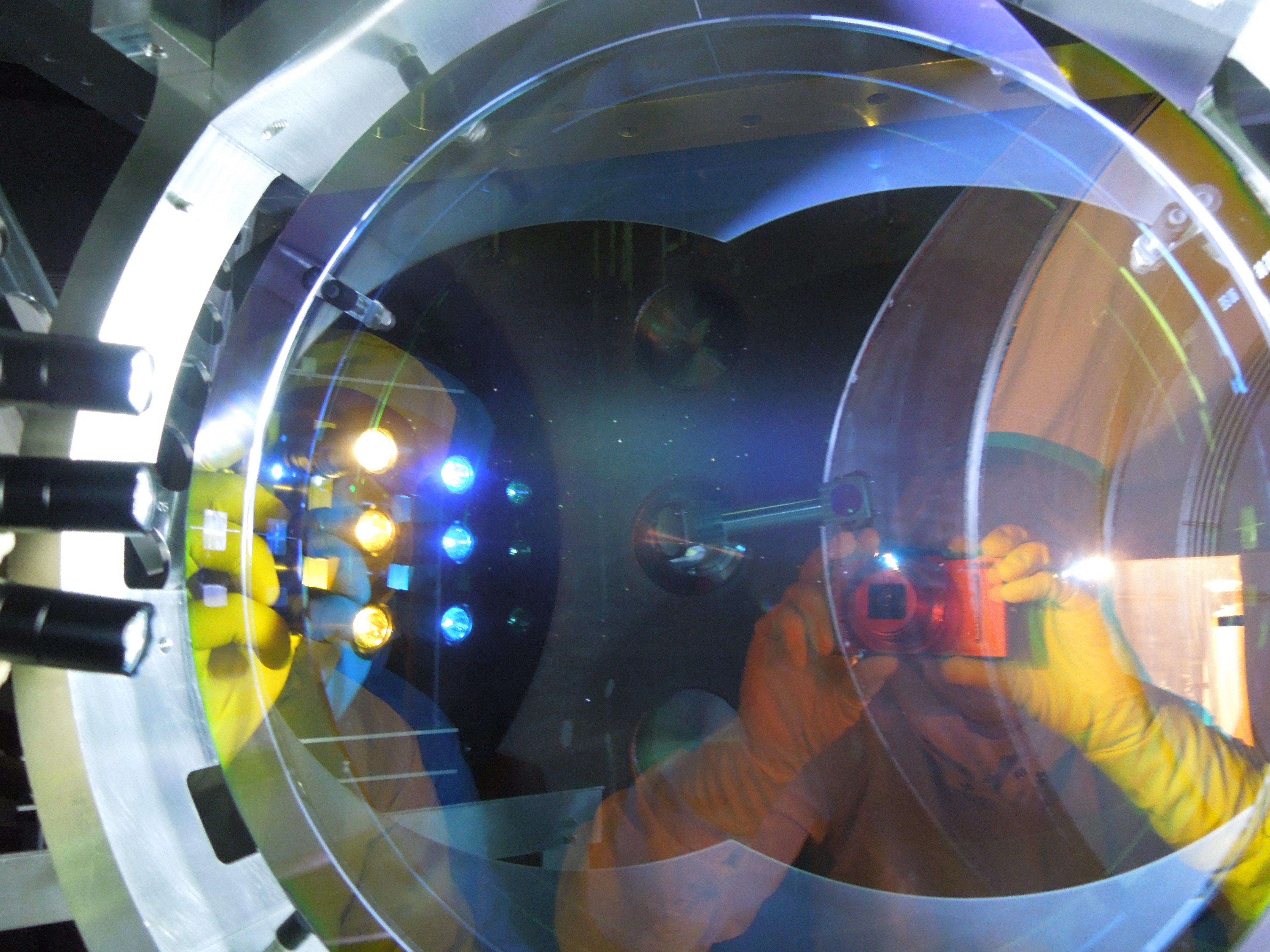
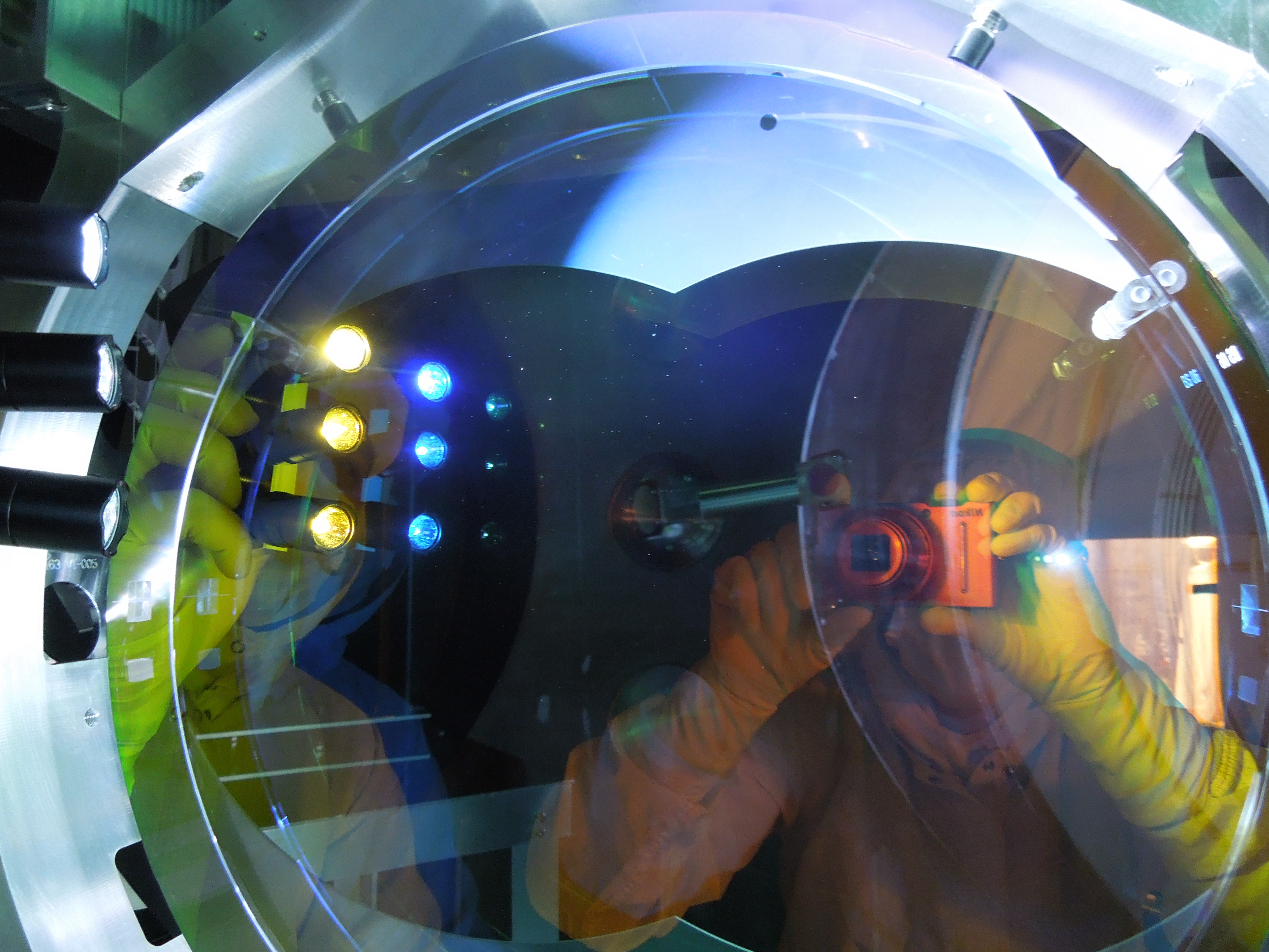
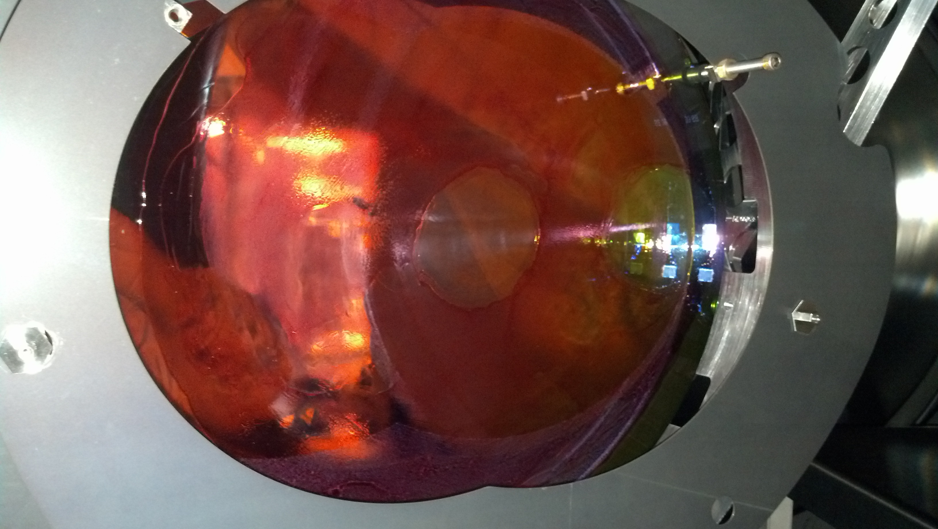
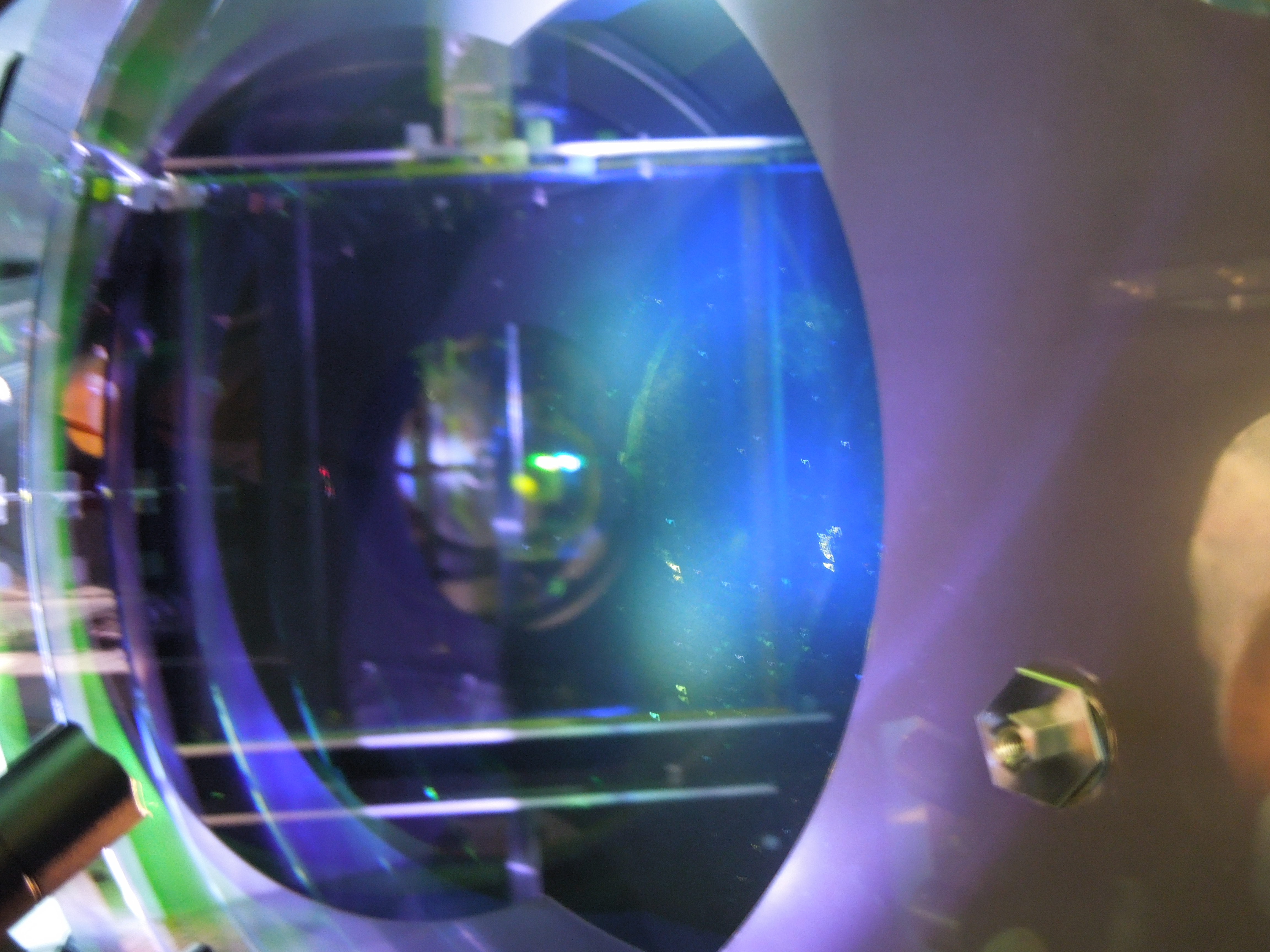
Note, we have officially walked away from HAM 2/3, turning them over to SEI who are now TF'ing. Which brings me to the PRM - the FC cleaning of this guy was a failure as there is major smearing/contaminant on the HR surface (see pic 3 attached). Of course, this is the one I did completely by myself without the Margot/Kate help, so apparently I did something wrong although not sure what since I was following their procedure and working with them. Michael reminds me that we do not used PRM in HIFOy so we will revisit cleaning on PRM again in 2 months. The MC1 - 3 FC cleaning this week removed some particulate although all 3 mirrors have a few particles within the central 1" area - particulate that I could not blow off with deion' N2.
Phew - SUS is finally done in HAM2, 3, and BSC2 - for NOW.