WORK PERFORMED
-----------------------------------------------------
1) Svn up the HAM-ISI MEMD screens and master models. (Terminal content doc)
2) Added "DAC" Macro Substitution to sitemap (See wiki)
3) Commited Sitemap (rev 4110) . SUS had Macro Substitutions Pending for commit.
4) Recompiled HAM2-ISI
5) Restarted HAM2-ISI
6) Made new Safe.snap files(2 xscreenshot)
8 4)->6) performed for HAM3-ISI
9) Tested Safe.snap:
- Turned ON the Master switch on HAM2-ISI
- switched to another Blend on HAM3-ISI
Restarted HAM23-ISIs, safe.snap files were loaded correctly in both cases.
10) Test WD: Lower Threshold & make sure we trip
11) Test DAC display: Drive 10counts (locked ISI) and see it appears on the wanted DAC channels of the Overview Screen.
12) Checked that the following channels
"
"H1:ISI-HAM2_MASTER_
_DRIVE"
"H1:ISI-HAM2_MASTER_
_DRIVE_DAQ"
...were available in DTT and DV
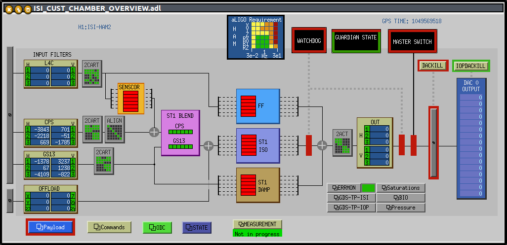
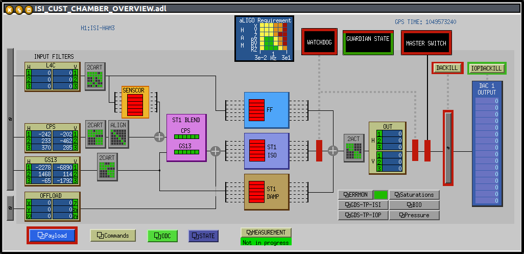
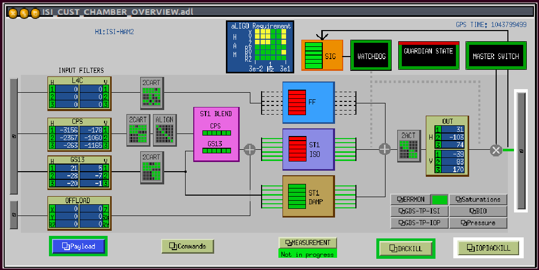
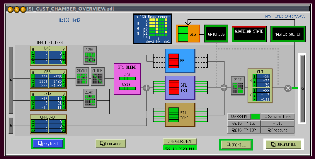
A new version of the ISI master models, and MEDM overview screen was recently made. The new Master Models and MEDM screens were installed yesterday, on the LHO-HAM-ISIs.
Details:
1) Svn up performed on the HAM-ISI MEMD screens and master models.
3) Commited Sitemap (rev 4110) .
Note: SUS had Macro Substitutions Pending for commit.
4) Recompiled HAM2-ISI
5) Restarted HAM2-ISI
6) Made a new Safe.snap file
8 4)->6) performed for HAM3-ISI
9) Tested safe.snap:
- Turned ON the Master switch on HAM2-ISI
- switched Blend filters on HAM3-ISI
- Restarted HAM23-ISIs.
safe.snap files were loaded correctly in both cases.
10) Watchdog tested by lowering thresholds to trip the ISIs on the different sensors/Actuators
11) New DAC display tested by driving 10counts (locked ISI) and making sure it appears on the wanted DAC channels of the Overview Screen.
12) Checked that the following channels
"H1:ISI-HAM2_MASTER_
_DRIVE"
"H1:ISI-HAM2_MASTER_
_DRIVE_DAQ"
...were available in DTT and DV