jim.warner@LIGO.ORG - posted 15:00, Monday 01 April 2013 (5952)
BSC6 ISI unlocked
BSC6 ISI unlocked, per Vincent's request.
BSC6 ISI unlocked, per Vincent's request.
[Corey, Kiwamu]
We replaced the two broken infrared QPDs that were in the POP QPD sled at HAM3 with the new ones.
After the replacement we confirmed that the new QPDs works fine. From the ISC point of view HAM3 is ready for pitting the doors.
QPD swapping
The broken QPDs (SN#39 in QPD1 and SN#53 in QPD2) [1] were replaced with the spares. The list below shows which QPD mount has which diode after the replacement.
QPD1 = SN#20 (the one close to the west door)
QPD2 = SN#24 (the one close to the north door)
We accessed the HAM3 table from the west and north side. We followed the same in-situ replacement technique as we did at EY [2] so that we don't have to remove the whole thing but we just swap only their QPDs. The replacement operation went quite smooth and was much easier than the last time when we performed it at EY where the optical table was suspended and freely swung. After the replacement we tested the QPDs by three ways : photo-current check with a hand-held QPD tester, diode voltage drop test and signal chain test with dataviewer. The QPDs signal made sense when we used the hand-held QPD while the QPD was illuminated with a visible red laser pointer. The voltage drop across each segment was approximately 0.36 V which seemed healthy. We were able to see signals at the IOP of the ASC front end with dataviewer although the signals were spiky since there was no anti-whitening filter for them. (In fact there was even no ASC front end model which takes care of these signals). From these tests we are confident that the new QPDs work fine and conclude that this mission is done.
QPD inspection
After the in-vac work we inspected the broken QPDs at the EE shop by inspecting the appearance and electrical characteristic. Filiberto looked at the QPDs with a magnifier and noticed that some of the wires were physically cut. The picture below shows a front view of one of the two broken QPDs. You can see that two wires, which are pointed by blue arrows in the picture, are cut. This is probably due to too much voltage (current) going through them when we were accidentally sending the picomotor driving signal which was more than 100 V due to the cabling error [1].
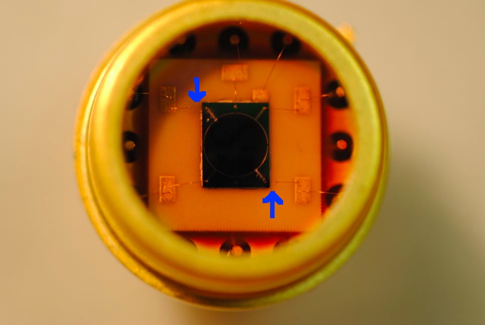
According to the electrical tests with a multi-meter, segment 2 and 4 of both QPDs are completely open as expected from the magnifier inspection. The rest of two segments are fine : they show 0.36 V voltage drop and the correct polarity. Note that this broken characteristic is different from that of the one we extracted from EY which was shorted [3].
Some notes
We fully removed the ISC-related tools from the HAM3 table so that we don't have to return to this chamber any more. However there was a thin metal plate left on the table which looked some kind of guard for the suspended mirrors. As we had no idea of what it was we left it in the chamber.
[1] LHO alog 5937 "HAM3 ISC IR QPDs are likely broken, in-vac cabling error, IO QPD should be OK"
[2] LHO alog 5718 "Comments on 'A new PZT mirror installed at ISCTEY and red in-vac QPD swapped on TMSY' "
[3] LHO alog 5942 " Broken infrared QPD of TMSY inspected "

| pin # | signal assingment in QPD cable (D1101624-v3) | signal assignment in picomotor cable (D1101516-v4) |
| 8 | QPD2 S | PM3 Y SIGNAL |
| 9 | QPD2 A2 | PM3 X SIGNAL |
| 10 | QPD2 A4 | PM2 Y SIGNAL |
| 11 | QPD1 S | PM2 X SIGNAL |
| 12 | QPD1 A2 | PM1 Y SIGNAL |
| 13 | QPD1 A4 | PM1 X SIGNAL |
| 20 | QPD2 C | PM3 Y RETURN |
| 21 | QPD2 A1 | PM2 X RETURN |
| 22 | QPD2 A3 | PM2 Y RETURN |
| 23 | QPD1 C | PM2 X RETURN |
| 24 | QPD1 A1 | PM1 Y RETURN |
| 25 | QPD1 A3 | PM1 X RETURN |
It looks that the reason why we had only segment 2 and 4 broken is due to the pin assignment.
In the above table you can see that the first half of the pins (of the DB25 cable) are assigned for segment 2 and 4 while all of them is populated by the picomotor SIGNALs in the case of the picomotor cable. On the other hand the 2nd half is shared by segment 1 and 3 where there is only RETURNs in the picomotor. When we looked at the picomotor signals from the control box using a breakout board the RETURNs didn't show any signals and hence I believe they behave more like ground in this setup. I guess we sent too much current on only these SIGNAL lines, resulting in melt of the wire in segment 2 and 4 while segment 1 and 3 survived because they are connected to RETURNs.
The test of the fifth BSC-ISI assembly is now complete. The testing report can be found at E1100298-v1.
MitchR, JimW, w/ Apollo Chris and Zach
The BSC2 ISI was locked and covered this morning in preparation for the Wed-Thurs power outage. The cover consists of one new BSC Dome Tall cover, a layer of ameristat taped down to the walking plates and a final BSC Dome Cover. Travis is in putting a cover on the locked SUS now. We might be going in again later, to lock HEPI, but otherwise the chamber is ready to be closed up.
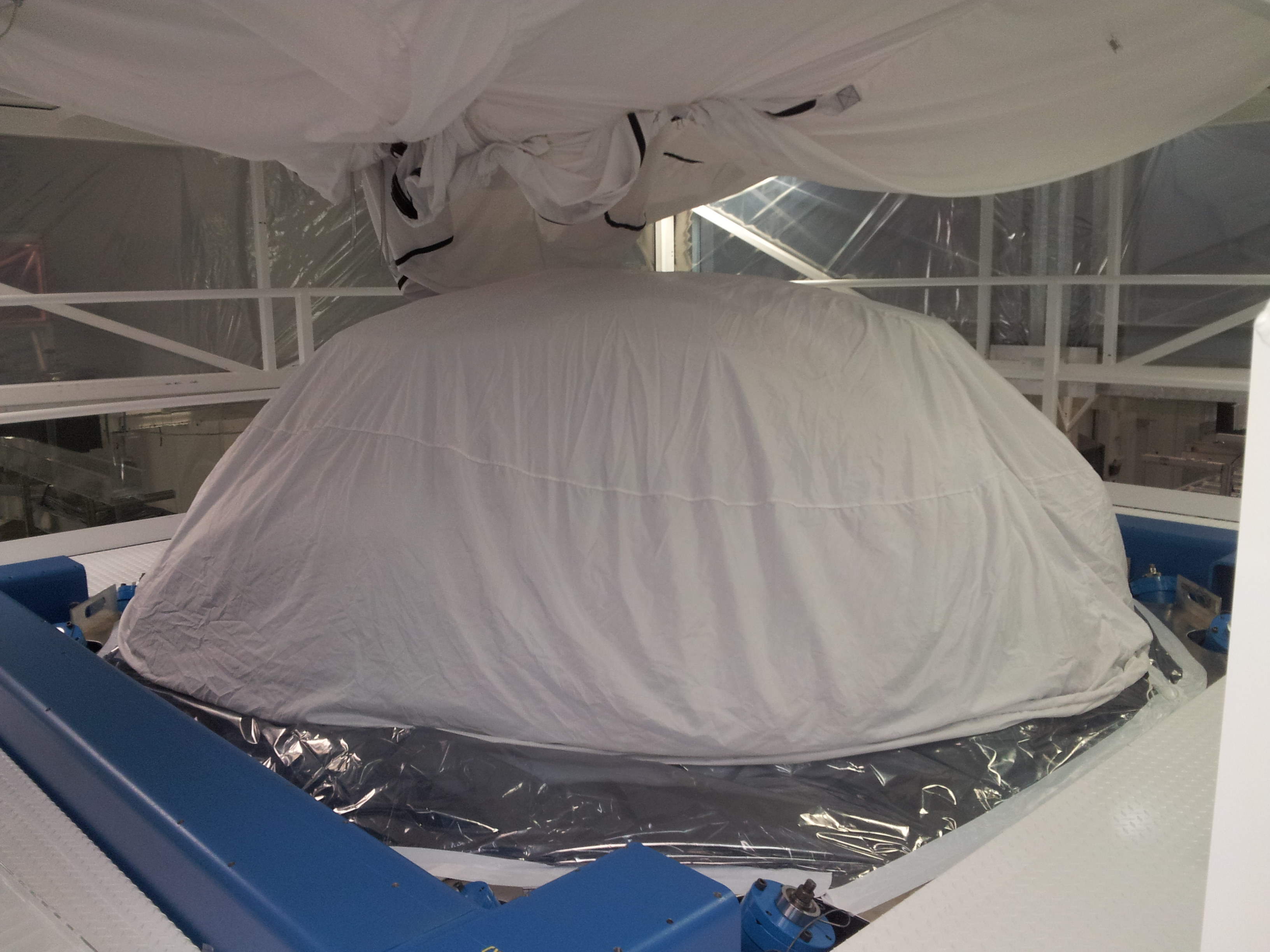
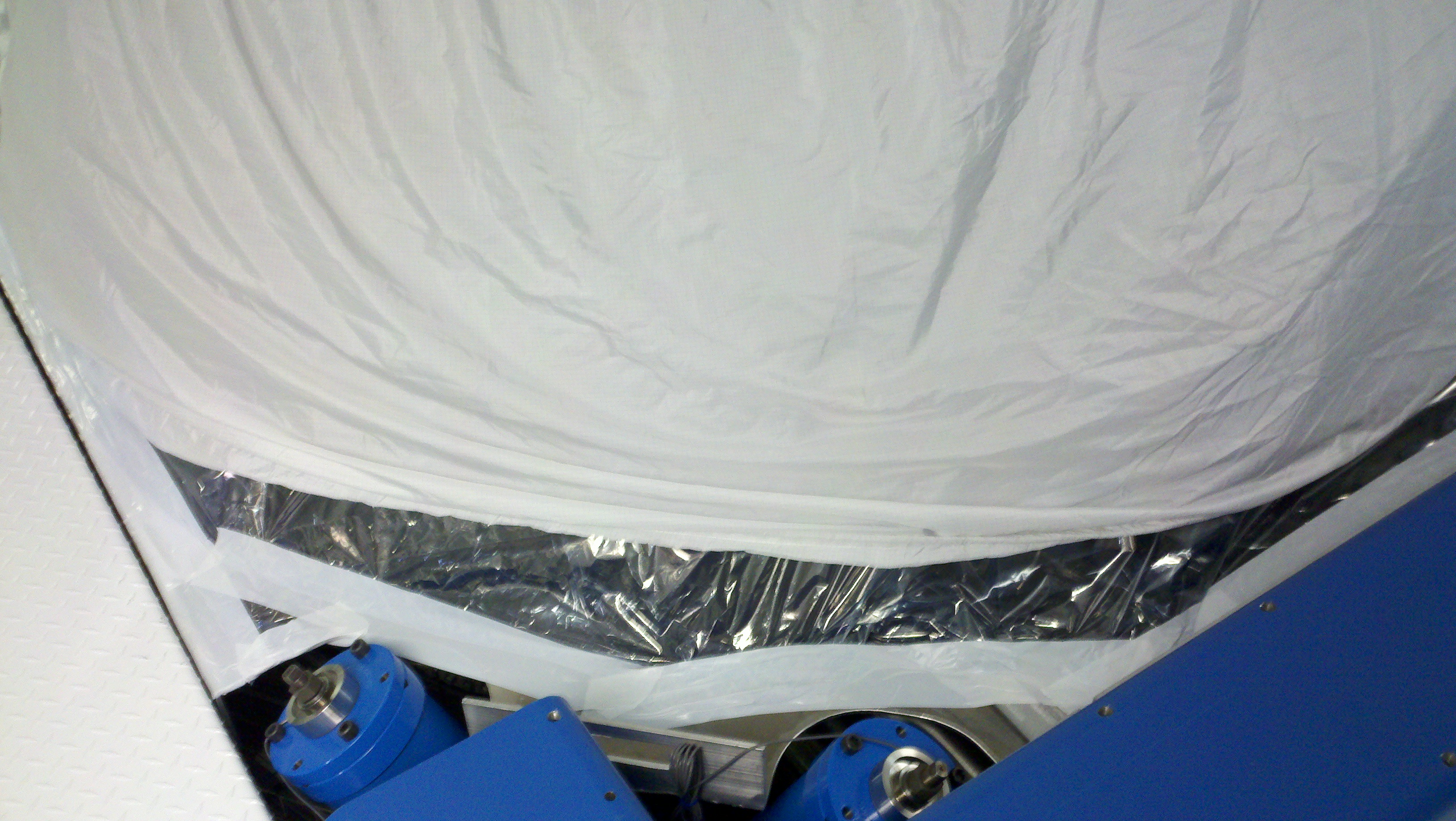
The beamsplitter now has a C3 cover. From a SUS perspective, the chamber is ready to be closed.
In preparation for the power outage Wednesday, the PSL and its relevant components have been turned off. Here is a full list.
For the LVEA racks:
For the diode room:
The HEPAs and AC units are still running in the laser and ante room, but will probably have to be turned off before the outage. The reason for this is that the AC units often need a manual restart, and if the software comes up after the power outage with the fans on, the room may overheat.
I transitioned the LVEA to laser hazard and looked at the beam in the IMC, working to understand the yaw needed on MC1 and MC3.

I reinstalled an iris (a 4th one I had made that was "extra") in front of MC1.  The iris I moved to MC1 is the one that IO had used in front of IM2, and then on REFL, and was not installed on any beam when I started.

The 4 irises we now have in HAM2 are:
- in front of MC1 - the extra one that has been floating around the table, that I moved to MC1 today
- in front of MC3 - installed after the last vent per the dog clamps I left on the table marking it's position
- behind MC3 (on MC trans) and before IM1 - installed after the last vent per the dog clamp I left on the table marking it's position
- downstream of PRM - installed last week by IO on the PRM trans beam

The only iris we have in HAM3 is at the edge of the table in front of PR2.  This was installed last week by IO on the PRM trans beam.

 I transitioned the LVEA back to laser safe.
This is a slightly outdated report, but I am writing this for completeness.
The broken infrared QPD (Q3000 SN3), which had been determined to be broken and was then removed from TMSY on 7th of March 2013 [1], was inspected at the lab. As originally suspected [2], indeed the 1st segment is not 'diode-ing' any more and it shows a small resistance of 2.8 Ohm regardless of the polarity. There is no obvious sign in the appearance of the diode. The rest of the segments looks quite healthy and exhibits a usual voltage drop of 0.44 V. Though interestingly the broken segment is still able to produce photo current when it is illuminated by a flashlight.
BTW, don't be confused by this report --- this is different from the newly broken QPDs which reside in HAM3 [3].
[1] LHO alog 5716 "A new PZT mirror installed at ISCTEY and red in-vac QPD swapped on TMSY"
[2] LHO alog 2865 "TMSY red QPD damage report"
[3] LHO alog 5937 " HAM3 ISC IR QPDs are likely broken, in-vac cabling error, IO QPD should be OK"
Attached are plots of dust counts > .3 microns and > .5 microns in particles per cubic foot requested from 5 PM March 28 to 5 PM March 29. Also attached are plots of the modes to show when they were running/acquiring data.

Data was taken from h1nds1.
T0=13-03-29-00-00-00; Length=86400 (s)
1440.0 minutes of trend displayed
Summary:
When we tested the in-vac picomotors on HAM3 again though these picomotors and also in-vac QPDs were tested OK before (here's the alog of these tests done by me, Cheryl and Daniel), nothing moved. Without these things, HIFO test never works.
The problem was traced back to an error in in-vac cabling. ISC IR QPDs were connected to the picomotor feedthrough and vice versa though I have no idea why this happened (see the comments attached to this entry for details).
The cabling was fixed and the picomotors now work again, but ISC QPDs are likely broken because of multiple attempts to drive picomotors back and forth, which put more than 100V on diodes. We used laser pointer to test the QPDs with the handheld QPD interface but were never able to convince ourselves that they're working. We forgot to test if any of the quadrants are short-circuited.
IO QPD for MC transmission should be OK as it is on a separate cable.
Anyway, we have spare QPDs and we'll replace them on Monday, entering HAM3 from the north opening. It's probably less than 2 hours for replacing, plus an hour for testing. We've done the same thing in EY and we know how to do this.
Spare S/N 20 and 24 from our stock of IR QPDs were bagged and left in a clean room by HAM2 so we can continue on Monday morning.
Picomotors and ISC QPDs both have two in-vac cable sections. The first section is routed to cable bracket 3 (CB3), then the second section goes from CB3 to the vacuum feedthrough, and apparently the second sections were crossed and mixed up.
Before we fixed the error:
| Cable Assembly | CB3 position | Cable | feedthrough |
| Picomotor D1101516/S1105245 | 2nd floor | HAM3 ISC QPD cable D1101658 / S1105085 | D3-3C2 |
| ISC QPD D1101624 / cannot read S/N | 1st floor | HAM3 picomotor cable D1101659/S1105100 | D3-3C1 |
After the problem was fixed (everything is consistent with D1101463 and D1002874):
| Cable Assembly | CB3 position | Cable | feedthrough |
| Picomotor D1101516/S1105245 | 2nd floor | HAM3 picomotor cable D1101659/S1105100 | D3-3C1 |
| ISC QPD D1101624 / cannot read S/N | 1st floor | HAM3 ISC QPD cable D1101658 / S1105085 | D3-3C2 |
Other things to note:
1. What happened?
It's really baffling as everything worked last September as I noted above.
Either things were mixed up from the start and somehow I managed to connect the test equipments (the picomotor driver and the QPD tester) to feedthroughs in a consistently wrong manner so everything worked, or things were OK back then but mixed up later for whatever reason.
Thing is, I remember having looked at D1002874 (Flange Layout H1 HAM3) and D1101463 (Cable routing configuration HAM 3) multiple times, especially former, before connecting the picomotor driver on the feedthrough exactly because I was worried to break QPDs (after all, this is not the first time we broke QPD, see this alog). It's extremely unlikely that what I did at that time was inconsistent with D1002874.
2. Picomotor driver unit 3 is funny.
During the testing, we disconnected the in-air cable from the picomotor controller for HAM1/3 (unit 3) and connected a picomotor directly to the front panel. It drove the picomotor, but it was VERY quiet and slow even though we selected the fastest pulse rate (500Hz) from the MEDM screen. No screeching at all.
We did the same test for the driver unit 4 that is used for ICST1/IOT2 and it was acting properly.
We never bothered to swap the Beckhoff cables of these units to see if it's a software problem or the drivers.
Anyway, if it turns out to be the driver, we'll swap it with the test unit that is sitting on the cart in the LVEA.
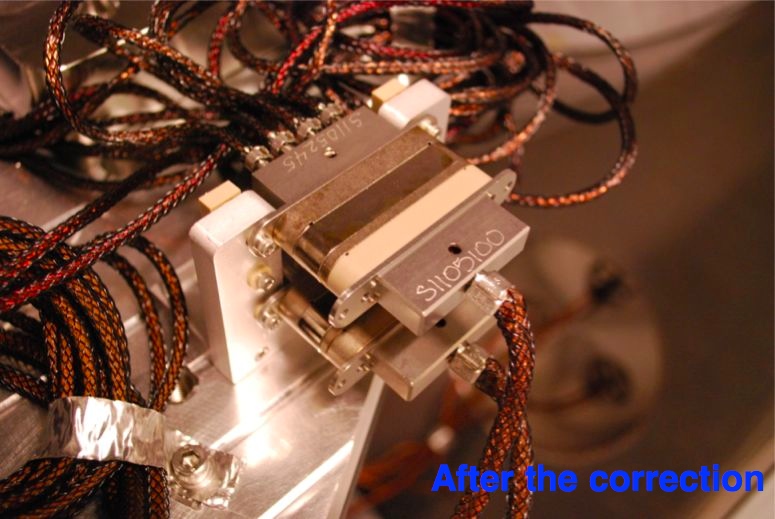
Here is a picture of the actual cable bracket. This was taken after we had fixed the cabling.

Richard cleaned the fiber this morning at the Y end patch panel, and after that we had 18-19uW at the table feed-through and I measured 14uW with the power meter in air on the table.  After realigning for the swapped beamsplitter, (and re-aligning the power monitor PD) the beatnote was -38dBm, around -20 dBm after the amplifier.

A plot of the OLG will follow,  but the main message is that the ALS PLL is working.  It has been locked for almost hours now, based on looking at the striptool of the beat frequency and the control signals.

The settings are: cg -15, fg 22, common compensation on, slow ugf set to -0.015Hz and slow pole set to 0.0001 Hz.

The beatnote frequency has glitches that are not present in the channel for the VCO frequency, where the signal level is much higher.  It might be easier to write an autolocker if we could get rid of those glitches, perhaps by amplifying the signal.
Chris, Max, Sheila-

Before Richard cleaned the fibers, Chris and I measured the power in the fibers at a few different places:
Input to fiber distribution box in R4: 1.2mW
Y end output of fiber distribution box: 75 uW
Max's polarization box: 60uW
Output at Y end patch panel: 10uW
At ALS table feedthrough:10uW
on ALS table at fiber output-approx 10 uW

Also the OLG of the PLL with the settings above is attached.
I changed the ALSLaser library, so that the polarity between the slow loop and fast loop is correct when the ugf setting for the slow loop is positive.

Also, when I came in this morning the PLL was still locked and looked like it had been for the last 10 hours.
Today we fine tuned the rotation of the HWP that rotates the polarization of the beam after the IMC. We followed these steps:
- we used an HWP at the bottom of the PSL periscope to set the polarization approximately "wrong", so to have considerable power transmitted through the unlocked IMC
- we used the HWP after IM1 to make sure that a good amount of power would go in the first forward rejected beam
- we rotated IM2 in yaw so that the first forward rejected beam would clear the FI and be transmitted all the way to (almost) IM4
- we position a power meter there
- we removed the HWP on HAM2, and rotated the HWP in the PSL so to minimize the power in the forward rejected beam. Because of the absence of the HWP in HAM2, this beam contained the "good" polarization: this way we made sure that the polarization off the PSL was as bad as possible.
- we steered IM2 back in its original position, and we placed the power meter in the main beam
- we re-inserted the HWP in HAM2 and optimized it to minimize the power in the main beam, thus rotating the polarization coming out from the IMC by 90 deg, that is what we want.
Unfortunately, during this process we had the opportunity to compare the beam out of the IMC with the re-routed IMC_REFL beam that had been setup couple of weeks ago and used since then as a more powerful reference for alignment. What we discovered is that the beams are not well aligned (more than a beam diameter at the FI). Note that:
The good news is that the situation can probably be easily recovered, without moving other components, using IM1 and IM2 to make sure that the current IMC beam is aligned, at the FI and further downstream, to the reference we have been using up to now. If the offsets turn out to be big, we may need to relieve them.
This morning I started floating the BS ISI, after asking SUSsers to lock their optic up. No real problems, beyond a missing wrench that had to be retrieved from staging and a CDS laptop that had too aggressive power saving settings (it would sleep the monitor after 1 minute, enough time to change out gloves...sigh). The ISI is currently floating within spec, cps were regapped where necessary, lockers were adjusted, the actuators were visually inspected for spacing, and cables were surveyed for rubbing. This should mean BSC2 is in a good position for in-chamber testing, but the BS is still locked.
- Mark L, and group changed pre-filters for AHU 1 and 2, per WP 3783.
- LVEA transition to laser safe at 9:00 am.
- Corey G. work in the squeezer area, East Bay of LVEA.
- Rick S, Michael R, and others to visit MID-Y, inventory of 3rd IFO PSL items.
- Jim W work at BSC2, top area.
- Betsy W and Filiberto C, work at HAM2, mission aborted.
- Betsy W and Travis S, BS is locked now.
- LVEA transition to laser hazard for IO work.
- IO group work, PSL enclosure --> HAM02.
- LVEA transition to laser safe, 3:32 pm.
- Joe, Giacomo, Cheryl

- Filiberto started the process to attach pins/connector to FI HWP pico motor.  Lack of information about the connector convinced us to push this out to at least tomorrow.

- the half wave plate was re-installed in the IMC trans beam path after IM1.  The beam through the FI was misaligned with IM2 to give an unclipped Forward Rejected Beam to minimize, which was minimized to around 40 uW of power.

- IOT2R was moved into place today, on the East side of HAM2, beams were aligned onto the single periscope and onto the table.  The table position needs to be marked before moving the table.

- beams transmitted through IM4 were measured - some measurements will be used to compare expected and actual transmittance of 2" fixed optics.  Actual power readings to be attached.

- AOE1 was aligned downstream of HWP per Rodica's instructions to move it along the beam path by 20mm.  With HA1 at 0, the front of the HWP is at 25mm , and the front plate of AOE1 is at 95mm along the beam path.

- PR2 scrapper baffle was installed.  Joe did the install, and centered the baffle w.r.t  the PR2 optic, since the beam at HAM3 iris was about a beam radius off in yaw, and off in pitch.  Earlier work of adding the HWP back into the beam path is the likely source of the change seen at PR2.  Using IM2, we deturmined that the correction was 100 slider counts or less, i.e. small.

Friday:
Plan is to flash the IMC, though there have been rumors of locking it in air...
Tried to connect/crimp the pins and connector for the Faraday Isolator. After going inside the chamber, noticed that the other connector that mates with the one I was installing is the same gender. We received a female connector and socket pins, but need male connector and pins. Have contacted Rich Abbot at CIT regarding getting correct parts.

Filiberto Clara
This are the power measurements we took on HAM to estimate the transmissivity of a number of optics. Measurement taken with filter inf ront of the sensr are specified (to account account for possible miscalibrations).
Incident on IM1 (filter on): 189 mW
Transmitted through IM1 (filter on): 6.25 mW
Transmitted through IM1 (filter on): 5.96 mW
NOTE: we did not realize that, because we were using the rerouted REFL beam, the polarization of the incident beam on IM1 was not as expected during operation. So this set of measruement is probably of (very) limited usefulness and will ned to be retaken. This does not apply to the following measurement taken at and after IM4, as only the right polarization remains in the main beam after the FI.
Forward incident on IM4 (filter on): 176 mW
Forward transmitted trough IM4 (filter on): .39 mW
Forward transmitted through IM4: 385 uW
Forward transmitted through ROM LH1: 30.5 uW
Forward reflected of ROM LH1: 361 uW
Forward incident on ROM RH3: 355 uW
Forward reflected of ROM RH4: 325 uW
Forward transmitted through ROM RH4: 25 uW
Forward reflected off IM4 (filter on): 175 mW
Forward transmitted through PRM (filter on): 5.4 mW
Backward transmitted through IM4: 380 uW
Based on the the above measurements, we can estimate the following transmissivities. Values in grey are calculated, not measured.
| Incident | Transmitted | Reflected | Sum | ||||
|---|---|---|---|---|---|---|---|
| IM4 Forward | 176 | .39 | 0.22% | 175 | 99.43% | 175.39 | 99.65% |
| ROM LH1 | .385 | .0305 | 7.92% | 0.361 | 93.77% | 0.3915 | 101.69% |
| ROM RH4 | .355 | .025 | 7.04% | 0.325 | 91.55% | 0.35 | 98.59% |
| PRM | 175 | 5.4 | 3.09% | 169.6 | 96.91% | 175 | 100.00% |
| IM4 Backwards | 169.6 | .038 | 0.22% | ||||

