patrick.thomas@LIGO.ORG - posted 18:42, Monday 14 May 2012 (2851)
plots of dust counts
Attached are plots of dust counts > .5 microns.
Non-image files attached to this report
Attached are plots of dust counts > .5 microns.
Last week, the HEPI actuators were driven after reattaching them to the boots. Few tests were performed:
- Linearity test (LHO_HPI_BSC8_Linearity_test_20120504T163242.fig)
- Range of motion (make sure there is 0.8mm amplitude)
- Transfer functions (10mHz-100mHz and 10Hz-500Hz) and comparisons with measurements before detaching the actuators (ISI unloaded for QUAD repairs). The comparison shows no/minor changes in the plant.
Note that the 100mHz and 10Hz points are linked.
https://svn.ligo.caltech.edu/svn/seismic/HEPI/H2/ITMY/Data/Figures/Transfer_Functions/Comparisons/L2L/
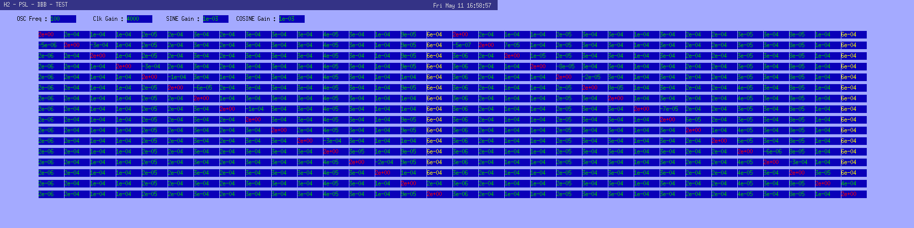
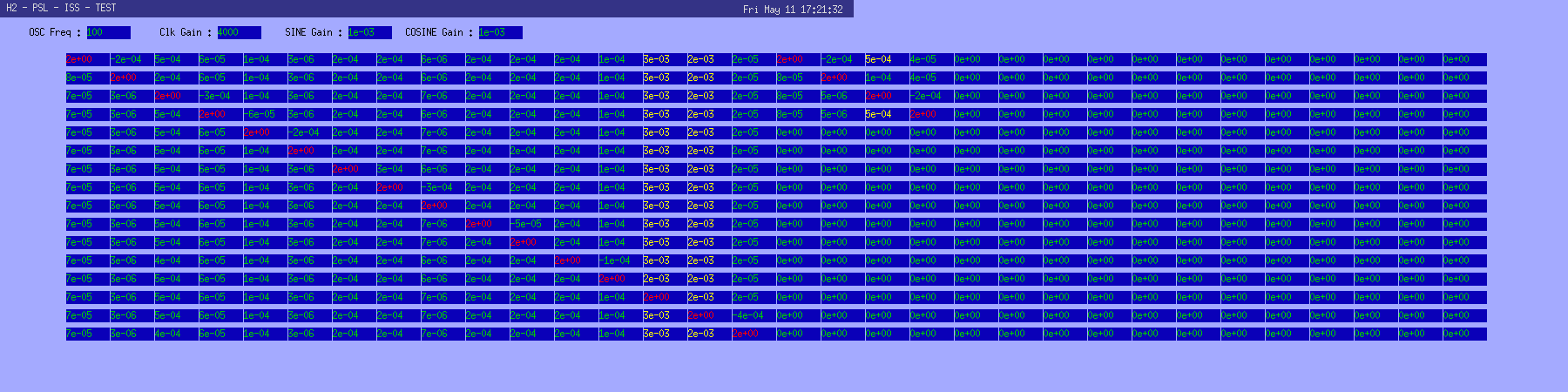
PSL installation team

We aligned the modematching between the HPL (200W laser) and the DBB as well as the modematching between the frontend (35W laser) and the DBB. The 200 mm quartz modematching lens inside the DBB box (on the rail) has been exchanged with a BK7 lens of the same focal length. The second lens on this rail (BK7, 80mm focal length, PlaKo) has been turned, such that the plane side faces to the first lens. On the MOPA path the 100 mm modematching lens has been exchanged with a 200 mm lens (both BK7).
We performed a modescan and measured 6.7% in higher order modes for the 200 W system and 4.9% in higher order modes for the MOPA.

We aligned the IS AOM (high power AOM), measured bandwidth: 3MHz.

The work on the rest of the beam paths is ongoing.
(corey,eric,jim)
HAM#5
Particle Fences were stripped off of HAM ISI#6 & installed on #5 (and then Mitch found our missing last two sets of Particle Fences).
Finished off the swap of Horizontal GS-13s, but did some serial number bookkeeping before walling things up.
Horiz Actuator s/n:
GS13s (vertical alread-installed)
GS13s (newly installed on 5/14)
HAM6
Particle Fences removed, Spring Covers installed.
Last week-end, we took a last set of transfer functions to build a nice reference and confirm that the ISI is ready. Note that some resonances (17Hz, 26Hz) observed in corner 2 (horizontals) during the previous measurements disappeared. I have attached a transfer functions comparison that illustrate the problem in stage 2 corner 2. The SUS crew worked intensively on the QUAD to solve rubbing issues, touching flags, miscellaneous adjustments, etc...; it can explained the differences between the two measurements. I superposed 3 horizontal transfer functions in corner 2 :
2012 02 03 : with FM and QUAD (fiber)
2012 04 27: with FM and QUAD (metal)
2012 05 12: with FM and QUAD (metal)
The last set of transfer functions can be found at:
*2012_05_12*
Following is the list of items that need to be completed (in roughly the order below) before we can close this chamber.  Some of the items have been finished and are still on the list as markers for redlining the installation procedure.  Please add a comment if I have missed any steps

1) Electrical grounding checks - DONE
2) IAS SEI alignment complete, ISI & HEPI floating - DONE
3) IAS ETMy alignment Round 1 - DONE
4) TMS alignment - DONE
5) ESD continuity check
6) Clamp ETMy EQ stops
7) Reapply FirstContact to ETMy-HR and ERM-AR
8) Swap Flooring - Waiting for FTIR on new set, can slip down list but not beyond 14a.
9) Viewport in-situ cleaning (or swap if deemed necessary)
10) TMS OSEM alignment
11) Close the ring heater and set fiber guard to "nominal" position
12) Unlock ETMy, remove all TFE except TM line stops, and physically check for rubbing as per T1200213 (still drafting)
13) ETMy BOSEM alignment, factoring in buoyancy as per T1100616
14a) ETMy testing (See Phase 3a G1100693)
14b) IAS ETMy alignment again (if testing showed interference and suspension was adjusted to fix)
15) Repeat step 14 until all Phase 3a testing is complete - usually done in 3 rounds in order to clear all issues.  Note, IAS requires removal of ETMy-HR FC completely.
16) TMS alignment check if needed
17) Lock down flooring nuts if loose
18) Set all EQ stops as per M1100256
19) Final FirstContact cleaning if needed
20) Remove TM line stops
21) Take pictures and count number of PEEK clamps
22) Set witness plates
23) Remove all tools
Shut the doors.
The good news is we're working down the list. The bad news is, I added a few more items to the list. Edited to reflect actual order:
1) Electrical grounding checks (moved down the list since it was DONE on the test stand, not on the chamber)
2) IAS SEI alignment complete, ISI & HEPI floating - DONE
3) IAS ETMy alignment Round 1 - DONE
4) TMS alignment - DONE
5) TMS OSEM alignment - moved up list since DONE
6) ESD continuity check
7) Clamp ETMy EQ stops - DONE
8) Reapply FirstContact to ETMy-HR and ERM-AR - (did not so ETM-HR since sheet was still somewhat intact) DONE
9) Swap Flooring - Waiting for FTIR on new set, can slip down list but not beyond 14a.
10) Viewport in-situ cleaning (or swap if deemed necessary)
11) SEI Electrical grounding checks
12) SUS Electrical grounding checks
13) Close the ring heater and set fiber guard to "nominal" position
14) Unlock ETMy, remove all TFE except TM line stops, and physically check for rubbing as per T1200213 (still drafting)
15) ETMy BOSEM alignment, factoring in buoyancy as per T1100616
16a) ETMy testing (See Phase 3a G1100693)
16b) IAS ETMy alignment again (if testing showed interference and suspension was adjusted to fix)
17) Repeat step 16 until all Phase 3a testing is complete - usually done in 3 rounds in order to clear all issues. Note, IAS requires removal of ETMy-HR FC completely.
18) TMS alignment check if needed
19) Lock down flooring nuts if loose
20) Set all EQ stops as per M1100256
21) Final FirstContact cleaning if needed
22) Remove TM line stops
23) Take pictures and count number of PEEK clamps
24) Set witness plates
25) Remove all tools
Shut the doors.
Update to closeout checklist:
1) Electrical grounding checks (moved down the list since it was DONE on the test stand, not on the chamber)
2) IAS SEI alignment complete, ISI & HEPI floating - DONE
3) IAS ETMy alignment Round 1 - DONE
4) TMS alignment - DONE
5) TMS OSEM alignment - moved up list since DONE
6) ESD continuity check
7) Clamp ETMy EQ stops - DONE
8) Reapply FirstContact to ETMy-HR and ERM-AR - (did not so ETM-HR since sheet was still somewhat intact) DONE
9) Swap Flooring - Waiting for FTIR on new set, can slip down list but not beyond 14a. DONE
10) Viewport in-situ cleaning (or swap if deemed necessary) IN PROCESS
11) SEI Electrical grounding checks
12) SUS Electrical grounding checks
13) Close the ring heater and set fiber guard to "nominal" position
14) Unlock ETMy, remove all TFE except TM line stops, and physically check for rubbing as per T1200213 (still drafting) DONE (PenRe has be relocked due to flag repair) Also, 1/4-20 x 3/4" vented screws installed for sleeve (these were overlooked in the making of this list).
15) ETMy BOSEM alignment, factoring in buoyancy as per T1100616
16a) ETMy testing (See Phase 3a G1100693)
16b) IAS ETMy alignment again (if testing showed interference and suspension was adjusted to fix)
17) Repeat step 16 until all Phase 3a testing is complete - usually done in 3 rounds in order to clear all issues. Note, IAS requires removal of ETMy-HR FC completely.
18) TMS alignment check if needed
19) Lock down flooring nuts if loose
20) Set all EQ stops as per M1100256
21) Final FirstContact cleaning if needed
22) Remove TM line stops
23) Take pictures and count number of PEEK clamps
24) Set witness plates
25) Remove all tools
Shut the doors.
Update to closeout checklist:
1) Electrical grounding checks (moved down the list since it was DONE on the test stand, not on the chamber)
2) IAS SEI alignment complete, ISI & HEPI floating - DONE
3) IAS ETMy alignment Round 1 - DONE
4) TMS alignment - DONE
5) TMS OSEM alignment - moved up list since DONE
6) ESD continuity check
7) Clamp ETMy EQ stops - DONE
8) Reapply FirstContact to ETMy-HR and ERM-AR - (did not so ETM-HR since sheet was still somewhat intact) DONE
9) Swap Flooring - Waiting for FTIR on new set, can slip down list but not beyond 14a. DONE
10) Viewport in-situ cleaning (or swap if deemed necessary) DONE
11) SEI Electrical grounding checks
12) SUS Electrical grounding checks
13) Close the ring heater and set fiber guard to "nominal" position DONE, AS MUCH AS IT CAN BE
14) Unlock ETMy, remove all TFE except TM line stops, and physically check for rubbing as per T1200213 (still drafting) DONE (PenRe has be relocked due to flag repair) Also, 1/4-20 x 3/4" vented screws installed for sleeve (these were overlooked in the making of this list). DONE
15) ETMy BOSEM alignment, factoring in buoyancy as per T1100616 DONE
16a) ETMy testing (See Phase 3a G1100693) DONE
16b) IAS ETMy alignment again (if testing showed interference and suspension was adjusted to fix) DONE
17) Repeat step 16 until all Phase 3a testing is complete - usually done in 3 rounds in order to clear all issues. Note, IAS requires removal of ETMy-HR FC completely. DONE (PENDING FINAL SET OF TFS TODAY)
18) TMS alignment check if needed IN PROCESS
19) Lock down flooring nuts if loose
20) Set all EQ stops as per M1100256 DONE
21) Final FirstContact cleaning if needed
22) Remove TM line stops
23) Take pictures and count number of PEEK clamps
24) Set witness plates
25) Remove all tools
Shut the doors.
Szymon Steplewski, Jeff Garcia, Mark Barton, Fred Raab

This afternoon we tested the ITMY lower stages to check whether the OSEM actuators were working correctly.  We found that upon exciting stage L2 the UL OSEM was not registering any change in the voltage monitor H2:SUS-ITMY_L2_VOLTMON_UL_MON, while the other three seemed to be responding to our excitation.  The corresponding NOISEMON channels also indicated that the UL OSEM was acting differently from the other three.

We decided to try injecting a 1 Hz sine wave excitation and looking at the time series of the VOLTMON and FASTIMON channels.  Our test confirms that each OSEM is responding correctly to this monochromatic drive, except for the stage L2 UL OSEM.  We will next diagnose whether this is a hardware or software related problem.

- TMS group worked at Y-END.
- SUS group TFs at ITMY.
- Outside visitor for well decommissioning, to pick up left items, drove past X-END station.
- Pump down of H1 input started, currently at 9.5 x 10^1.
- Apollo staged items for ICC, by HAM4/BSC2 per permit 3210.
- Cleaning crew cleaned HAM4/BSC2 area per permit 3213.
- PSL group at H1-PSL area, in and out of enclosure.
Work permits were signed and filed after morning meeting. The cleanroom from BSC3 was moved to BSC2, the East Bay cleanroom was moved over HAM4 and then both chambers were cleaned. The viewports and feedthroughs were removed from HAM4 north door and the north door was removed from the chamber.

The plan is enter at HAM4 ASAP tomorrow and get the sampling done on the BSC1 Elliptical Baffle and then de-install it. Then we'll install dust barriers and remove BSC2's dome so that the SEI stack can be removed before lunch tomorrow.
Both the main beam path as well as the HWS path was aligned. Though the centering on each optics is not necessarily perfect, everything is far from clipping and I call it good enough.
Picomotors for the green injection were swapped with modified units to prevent the "stop ring"s on the tip of picomotors from interfering with Siskiyou mounts. To be exact, one spare pair was modified and replaced the one on the TMS table. Another pair that was on the TMS table was pulled out, modified and put in place.
We originally modified two spares, but have found that one modified picomotor was broken. This is the one which was on the table in the EY lab, and it's not clear to me if the modification broke it or if it was already broken.
Anyway, the injection picos work flawlessly now. We haven't done this modification to the red picos.
The returning beams look ugly, and it's difficult to say what is responsible for what. A part of it should be the ugly beam injected (we'll look into it later). But it's also possible that a part of it is coming from not-that-perfect TMS telescope alignment, i.e. the TMS telescope might be tilted in relation to ETM and we're compensating for the tilt using the alignment of the ALS table. This is not a big deal for the one arm test, though, and is good enough for start injecting green beam to the arm. We won't delay the installation because of this. (But we need to analyze the injected beam as well as the returning beams, which can be done without going into the chamber.)
Picomotor modification picture: https://ligoimages.mit.edu/filestore/1/9/3/2/0_bd6d89c33a325dd/19320scr_3faebab47e425a5.jpg?v=2012-05-10+21%3A24%3A09
Left is stock, right is after modification. We modified both in the end.
BTW, we needed to tilt the TMS in PIT for some non-negligible amount. So much for initial alignment under the test end.
We had to move 50-gram weight because the OSEM offset didn't do it. After finer alignment, 50-gram weight is positioned to relieve the OSEM offset in PIT.
We were initially running the old H2 IO Chassis for the H1 PSL. However we found two ADC channels had large DC offsets (in the first and third ADCs) and the duotone had bleed-through into the adjacent channel. We re-ordered and re-seated the cards, but the problem did not change. We then installed the H1 PSL Chassis and the problem was resolved. We will run the old H2 IO Chassis on a test system to determine if the problem was caused by bad ADC cards.
While working in BSC6, I looked at the two high quality viewports on the South door.  I found that both have cleanliness issues, on the inside surface, that are consistent with failed cleaning practices.

On the South door, the East viewport has a line that is about 4 inches long, and is in a shape that is consistent with a smear from a solvent being allowed to dry on the surface.  The West viewport  has approximately 10 droplets, with some up to 2 mm in diameter, that are consistent with water/soap droplets being allowed to dry on the surface.

Next week, the history and inspection reports for these viewports need to be reviewed, and possibly a plan made, to try and clean them in-situ.

Pictures are attached.
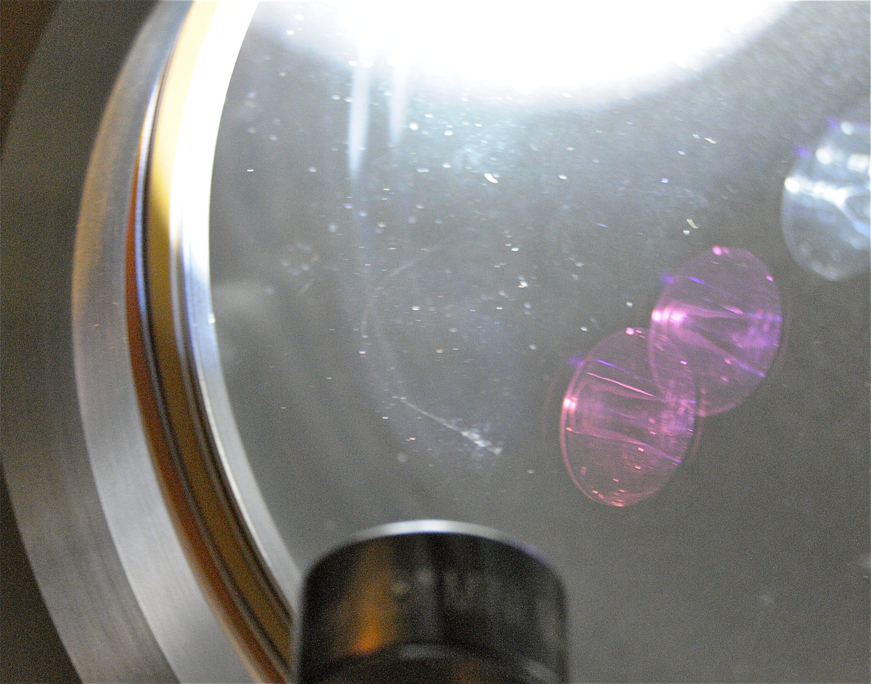
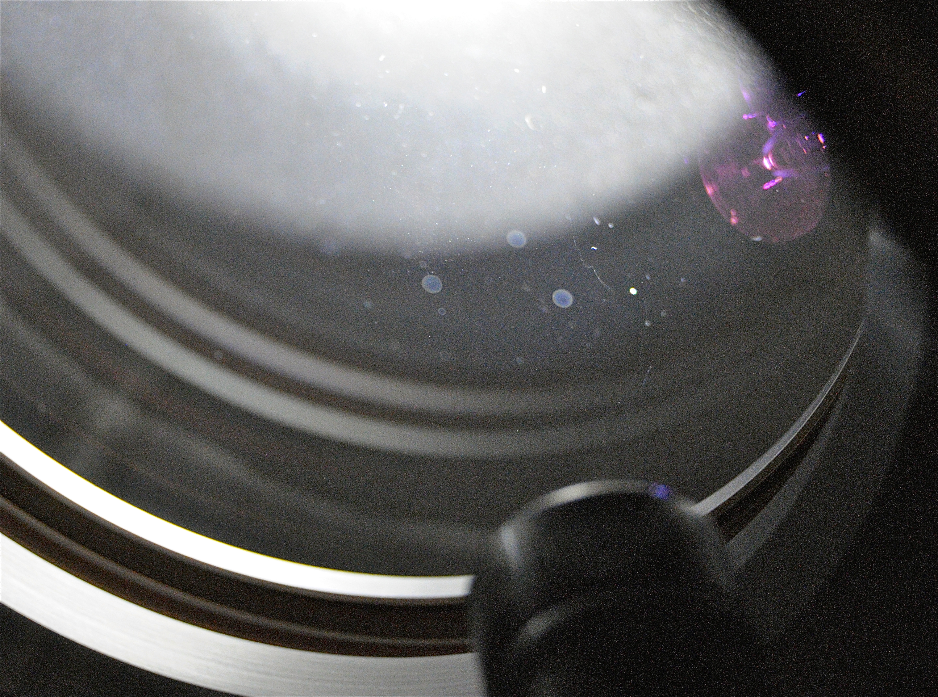
Betsy and I have done a little investigating this morning.
Nominally, the life cycle of a custom viewport looks something like this:
Incoming inspection (Condition-dark background, bright light, looking for gouges/dings etc)
Cleaning (We're on about the sixth version of the viewport cleaning procedure at this point so we'll check and try to determine just how these viewports were cleaned. Some possibilities: Liquinox with bake, methanol with bake, freon without a bake)
Assembly (Very possible for stuff to be deposited during this phase.)
Post-cleaning inspection/proofing (QA process-Worth a check to see how process takes place and whether/how the process may contribute to the particulate load and whether there is anything that may cause spotting. Nominally, the testing set up is Class B.)
Installation (There is always the possibility that IPA was used during the install to aid bolt torquing.)

There are a few things we can try for clean-up: First Contact, methanol drag wipe, freon drag wipe.
Today Patrick and I made some good progress on interfacing the H2 ISC slow controls with the greater IFO controls.
I have created a global name space structure library that will be our interface to the TwinCAT/Beckhoff/OPC system. This library, Ifo.lib, will be imported by every PLC. It's leaf nodes are the variables that are written to and read by the PLCs, and will be translated into EPICs records.
We fleshed out the ISC PLC that will be run on the H2ECATY1 slow front end chassis: PLC1.pro. It imports the Ifo.lib library and defines a single global variable:
H2: IfoStruct; (*~ OPC:1 *)
The PLC executes three tasks, one for each of the attached slow chassis:
These three program tasks execute the various functions blocks that are the interfaces to the attached hardware modules, and the IN_OUT variables for those function blocks are elements of the global Ifo structure. For instance:
PROGRAM ISC_Common_Chassis
VAR
  Vco:           LowNoiseVcoFB;
  VcoIn  AT %I*: LowNoiseVcoInStruct;
  VcoOut AT %Q*: LowNoiseVcoOutStruct;
END_VAR

Vco(
 LowNoiseVcoIn  :=  VcoIn,
 LowNoiseVcoOut  => VcoOut,
 LowNoiseVco    :=  H2.Isc.Als.Ey.VCO);
The global variable H2.Isc.Als.Ey.VCO... is exported as an OPC variable, is in turn exported as EPICS record H2:ISC-ALS_EY_VCO...
We managed to get some test variables talking to hardware, exported as OPC variables, and showing up as EPICS records that were accessible from CDS workstations.
All new code was committed to the "slowcontrols" SVN.
There's still a lot more fleshing out to be done, both for Ifo.lib, and the ISC PLC1 for H2ECATY1, but I think we have a path forward (pending approval from Daniel).
I will continue to work on documentation, particularly the library document for Ifo.lib. It would also be really nice to have a block diagram that describes in more detail the hardware/software interface, for reference.
Attached are plots of dust counts > .5 microns.
After the replacement of the PSL DCU (we had moved the H2 DCU over to serve as H1 DCU but found a channel on two of the ADC cards, hence the DCU build for H1 was installed) the loop-back tests were redone.
The H1 input mode cleaner volume (HAM1, HAM2, and HAM3) is ready for pump-down and leak testing.  The blanked-off septum plate between HAM3 and the spool which connects HAM3 to BSC2 (which will experience the pressure difference) is fully restrained as the spool bellows and the HAM flange bellows are prevented from elongating or compressing via tie-rods.  If this detail were overlooked, the HAM flange bellows would become fully compressed and likely damaged with the HAM3 side under vacuum and the BSC2 side vented.

The 8" gate valve+turbo combination that had been mounted on eLIGO HAM6 was moved to the west door of HAM2 as a temporary means to pump this volume and will be removed later.  The nominal turbo mounted atop HAM1 could not be used as its controller cable was too short (longer one to be ordered).

Pumping was not begun as I am leaving soon and the roughing portion (pumping with only scroll pump) ought be monitored periodically so that adjustments can be made to the isolation valve set-point as the volume's pressure falls.  I will send Gerardo the details such that he can pump during the day while he is here next week.
H2 SUS ITMY M0 & R0 transfer functions for the night of 05/10/2012. Initial analysis of the results look very promising for a BSC 8 chamber close-out. Final decision for a door-close on BSC 8 from the SUS team to follow.
While hunting for the source of the rubbing leading up to these measurements, it was found that the OSEM cabling leaving the top of the top mass had sagged and was contacting the tablecloth. I pulled some of the slack out of this cable through the clamp on the upper structure reducing the possibility of it rubbing in the future. Also, during this work, it was noted that the M0 BOSEMs were showing a lot of cross coupling between DOFs. I recentered all of the top BOSEMs on the main chain, and Garcia confirmed that this seemed to have reduced the coupling.

