This morning, Fil finished running the external PR3 and PRM cables from the chamber feed thru (port D3) to the R1 rack. Travis and I then connected the internal quadrapus cables from the PR3 and PRM to the D1000225 SRS cables that run down the ISI to the inside of the feedthru port. The signals all seemed to come out in the appropriate places on medm so so far, so good. We laced and stowed the cables for PR3 and then suspended the mass to verify the health of it's signals. The M2 and M3 stage OSEMs were not perfectly well aligned, so the chamberside table is not as well leveled as the ISI, causing the suspension to hang differently in the cage now. We tweeked a few top BOSEMs such that we can take TFs in prep for IAS alignment in a few weeks. (The M2 and M3 stage OSEMs don't get aligned until after that alignemt).
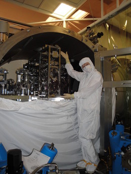
In order to work on PR3 I had to stand in the beam tub on the HAM3 side of the HAM2 chamber.
While there, I also:
Picked up the older witness plate that was in the beam tube near HAM2.
Moved the newly placed witness plate (laid a few days ago) into a metal holder since it was vulnerable to breakage from standing near it.
Relaced the 4 SRS cables for CB1 and CB2 (PR3 connections) up the ISI, taking care to not ground between the ISI stages. I did not have nearly enough slack to place the CB brackets in their appropriate spots on the table so I needed to pull from underneath the ISI and reclamp down the slack. The cables I moved were laced up the NE corner of the HAM2 ISI. SEI will make sure the lacing is appropriate when they test later in the month.
Added metal face shields to the PR3, MC1, MC3 - HR side of the suspensions - all are freely suspended though.