[Cheryl, Giacomo]
Last Friday (February 1st), just before I left, Cheryl and I repeated the measurements of the IMC cavity pole using the same setup I had prepared the previous week.
We took the measurement twice, using two slight variations:
- measure the transfer function TF1 between the the ISS PD and the PD on the IOT table, in reflection of the unlocked and misaligned IMC. Then measure the transfer funtion TF2 between the ISS PD and the same PD on the IOT table, but moved in the transmitted path of the locked IMC. The ratio TF2/TF1 should give the IMC TF.
- measure the transfer function TF1 between output of the SR785 and the PD on the IOT table, in reflection of the unlocked and misaligned IMC. Then measure the transfer funtion TF2 between the SR785 and the same PD on the IOT table, but moved in the transmitted path of the locked IMC. TF2/TF1 should give the IMC TF.
The good news is that the two measurements are in very good agreement with each other (as expected and hoped); the bad one is that they are not well fitted by the expected TF.
Attachments:
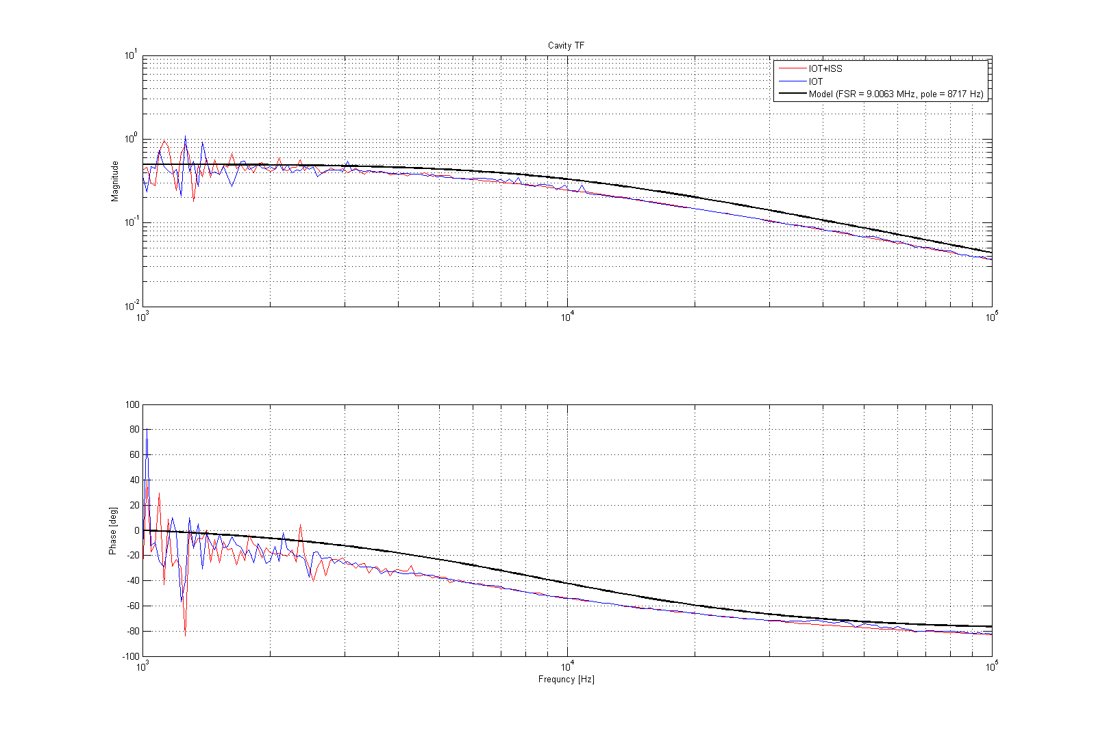
1) the magnitude and phase of the IMC TF as measured using the two techniques, and compared with the expected value
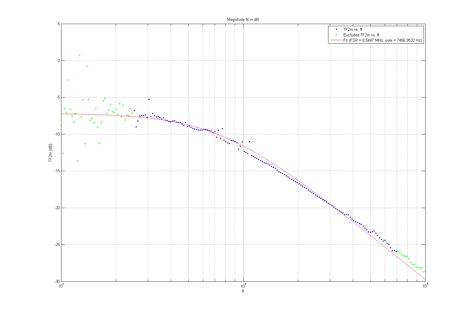
2) a fit to the magnitude (in dB) of the TF, between 2.5 and 70 kHz (for comparison with LLO measurement that can be found here, and I believe was fit in this range)
It might be worth repeating the measurement with a different PD and maybe with an instrument that can go higer in frequency.