kyle.ryan@LIGO.ORG - posted 15:24, Friday 08 February 2013 (5430)
Started leak-checking at X-end
Found BSC5 dome annulus is leaking badly -> Will spray new CF joints next week
Found BSC5 dome annulus is leaking badly -> Will spray new CF joints next week
Vincent told me that H1 TMSY was ringing up when the damping was on. BIO was working.
Eventually I found that I had to turn down the damping gain of all rotational modes by half, plus turn off ELF10 filters in the coil outputs, to get going stably. Since there is zero reason to go aggressive under the air, I'll leave them like that for now.
H1:SUS-TMSY_M1_DAMP_R_GAIN is -10 instead of -20.
H1:SUS-TMSY_M1_DAMP_P_GAIN is -5 instead of -10.
H1:SUS-TMSY_M1_DAMP_Y_GAIN is -5 instead of -10.
All ELF10 filters are disabled instead of enabled.
My guess is that somebody decided to go aggressive under the vacuum a long time ago, and now, in the air, OSEM positions are different and that makes coupling between DOFs different, causing oscillations.
Viton pads are usually set under the balancing masses of the HAM-ISIs in order to damp resonances at high frequencies (above 100Hz).
The SEI team would like to asses the improvements that the Viton Pads help achieving. To do so, we decided to have viton pads under the balancing masses of the ISIs of LLO's IMC, and to try without those pads here at LHO.
Transfer functions were measured ovenight on LHO HAM3-ISI. We compared those transfer functions with the ones measured at LLO under an equivalent state:
Comparative plots are attached.
The script which produced the plots mentioned above was re-checked. The curves it displays match with the ouput of the generic commissioning scripts, for both LLO and LHO.
Data in the 5Hz-200Hz range was retreived and added to the plot. Results are attached.
The results presented above were calibrated and transposed into the cartesian Basis, as performed during the step 3 of the commissioning process of HAM-ISIs.
Narrow peaks can still be seen on LLO's transfer functions. We held off on the installation of the Scraper Baffles here, while they were already on the ISI at LLO, at the time of the measurement. It could be the cause of it.
Once HAM3 chamber is open, we will look at the items installed on the ISI. It should help clarifying the cause those peaks that we did not witness here.
I attached a picture of HAM3 chamber taken on Dec 6th 2012. Pumpdown started on Dec. 21st.
I acknowledged the following alarms Friday morning:
All of these cleared when acknowledged except the IOP which remains yellow.
The Apollo crew removed the ISI from BSC 10 and placed it on the north side of the termination slab, wraped, bagged and sealed. We chose to stand down on the ICC for now, instead we relocated the clean rooms that were over HAM 4 and BSC 1 and began disassembly of the E module and work platform around BSC 1 to be relocated to BSC 2.
At approx 08:10 this morning the network to the EX FMCS system and the wall camera was disrupted. Upon investigation we found that the ethernet cable in the VEA rack was disconnected. This cable had an extender and a 6 feet additional ethernet cable before it plugged into the Foundry switch. The connection at the extender was disconnected. We found that the extender was not needed any more and plugged the long haul cable directly into the switch.
Dan from LDAS worked on the h1ldasgw0 system to investigate why h1fw0 has become unstable since last Wednesday 30 Jan with apparent disk write slow downs. He upgraded the firmware, we then restarted the h1fw0 writer. Jim has made h1nds1 the default nds because of this problem so the shutdown had minimal impact.
After h1fw0 was restarted we restarted the DAQ due to an 0x2000 status on h1hpiham1. It appears that the model change earlier made channel number changes and a change in DQ channels (perhaps a common model was changed recently).
The magnetized PR3 optic was loaded into the custom ABO today for a 6 hr. ~34 degC air bake.
Yesterday, we installed the PRM optic in the suspension. Today, we adjusted roll and suspended it. It has a bit of a pitch which we will need to work out tomorrow - the top mass is ~level and the optic is ~level, but the middle mass is pitched. So, it's either the top mass blades, or middle mass weight configuration inducing pitch. WIll confer with others and make adjustments tomorrow. Preliminary height measurements do not indicate any major height problems. Final numbers/tols will come later after tweeked.
I really didn't get to any L4C leveling but unlocking is the first step so I did get started on this long pending task.
Please be mindful of the signs and avoid the blue Crossbeams.
Activities for today:
- Pole cavity measurement, PSL room, Michael R., Rodica M. and Paul F.
- Jim B., One-stop card addition, see his aLOG.
- Eric A., working around WBSC02, no cranning needed.
- Hugh, Cable relief at WHAM02.
- Ski, working fixing X-Mid intrument air.
- Kiwamu, ALS path work, PSL area.
- Praxair, LN2 delivery CP1.
- Kyle work at the input tube large ion pumps.
- Hugh, work at HAM01, HEPI is unlocked now.
- Dave and Jim, visited X-End troubleshooting FMCS/camera communication issues.
The communication problem with X end FMCS has been fixed
Had found stuck open previously and had valved-out -> Now all (5) compressors are valved-in
Used for fall protection whilst atop MC tube (Connecting HV cables to IP1 and IP2)
Replaced bad solenoid on Drying tower, system is now back up and running
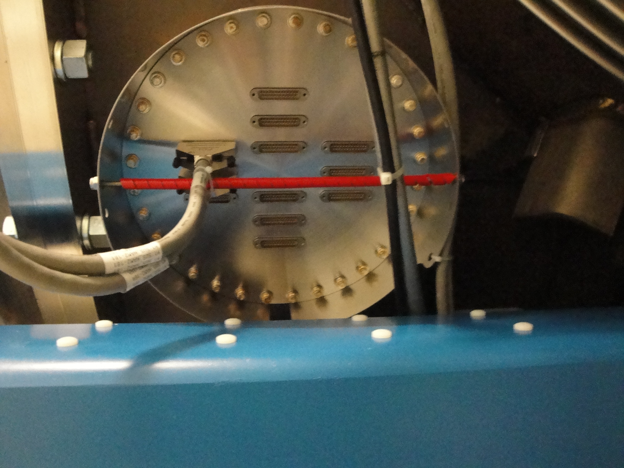
See the attached photo showing how I've schemed Cable Stain Relief on this 12" 12 plug Feed Thru.
There are holes on the perimeter of the Shroud allowing an all thread to pass between cables.  The red cable conduit protects the cable from the threads.  All cabling should get strain relief and there are a lot of cables on D6(SW Corner) none of which have any relief yet.  There are still a lot of cables yet to be plugged into D3(PRMs.)  If anyone objects to this scheme or thinks installing these should wait until... please let me know.
Added reworked one-stop card to I/O chassis for h1susauxb123. Powered up chassis, then powered up h1susauxb123 computer to verify that all cards could be seen. Note that no AA chassis are attached to this I/O chassis yet.
Added a reworked one-stop card to the h1susauxh23 I/O Chassis, then powered up the chassis. After about 15 seconds, the chassis died with what appears to be a bad power supply. This was suspected before, but it hasn't been replaced yet.
Added a reworked one-stop card to the h1seib2 chassis, ran timing fiber from the ISC fanout to the I/O chassis. Did not power up, as it appears there is a binary I/O card missing from the chassis.
The channels for the IPS (Inductive Position Sensors) were connected in the model of H1:HAM1-HEPI: h1hpiham1.mdl
Model was restarted at 11.02am. Readouts make sense. The new model is now commited to the SVN.
