kyle.ryan@LIGO.ORG - posted 15:46, Friday 07 December 2012 (4863)
Corner Station QDP80s serviced
Changed gear-drive oil -> both Corner Station pumps -> 400CC Krytox 1525 -> routine maintenance
Changed gear-drive oil -> both Corner Station pumps -> 400CC Krytox 1525 -> routine maintenance
It was noticed yesterday that the Left and Right OSEMs on ITMy MO stage were  noisier than the other OSEMs.  I began to investigate this looking at the signal into the AA chassis and it to exhibited noise but looked like it was missing the - part of the signal.  I was able to trace it back to the Sat box.  I replaced the box and will look into the noise problem on it with a full blown test.  The signal should be okay now.

Of particular note.  The MEDM screen for the sus did not show this only the IOP at he higher sampling rate saw the noise.
Yesterday, it was mentionned in LHO aLOG 4858 that transfer functions measured on BSC1 were different from what we expected. This morning, I ran some simulations to evaluate if the extra modes seen in the [5-8]Hz frequency band would create some difficulties in the control design.
For the test, I used the BSC6 damping and isolation filters.
The 12 main transfer functions once the ISI is damped:
https://svn.ligo.caltech.edu/svn/seismic/BSC-ISI/H1/ITMY/Data/Figures/Transfer_Functions/Simulations/Damped/
The 12 main SISO TF used for the control design (between every steps, the MIMO response is used) are given below:
https://svn.ligo.caltech.edu/svn/seismic/BSC-ISI/H1/ITMY/Data/Figures/Transfer_Functions/Simulations/Isolated/
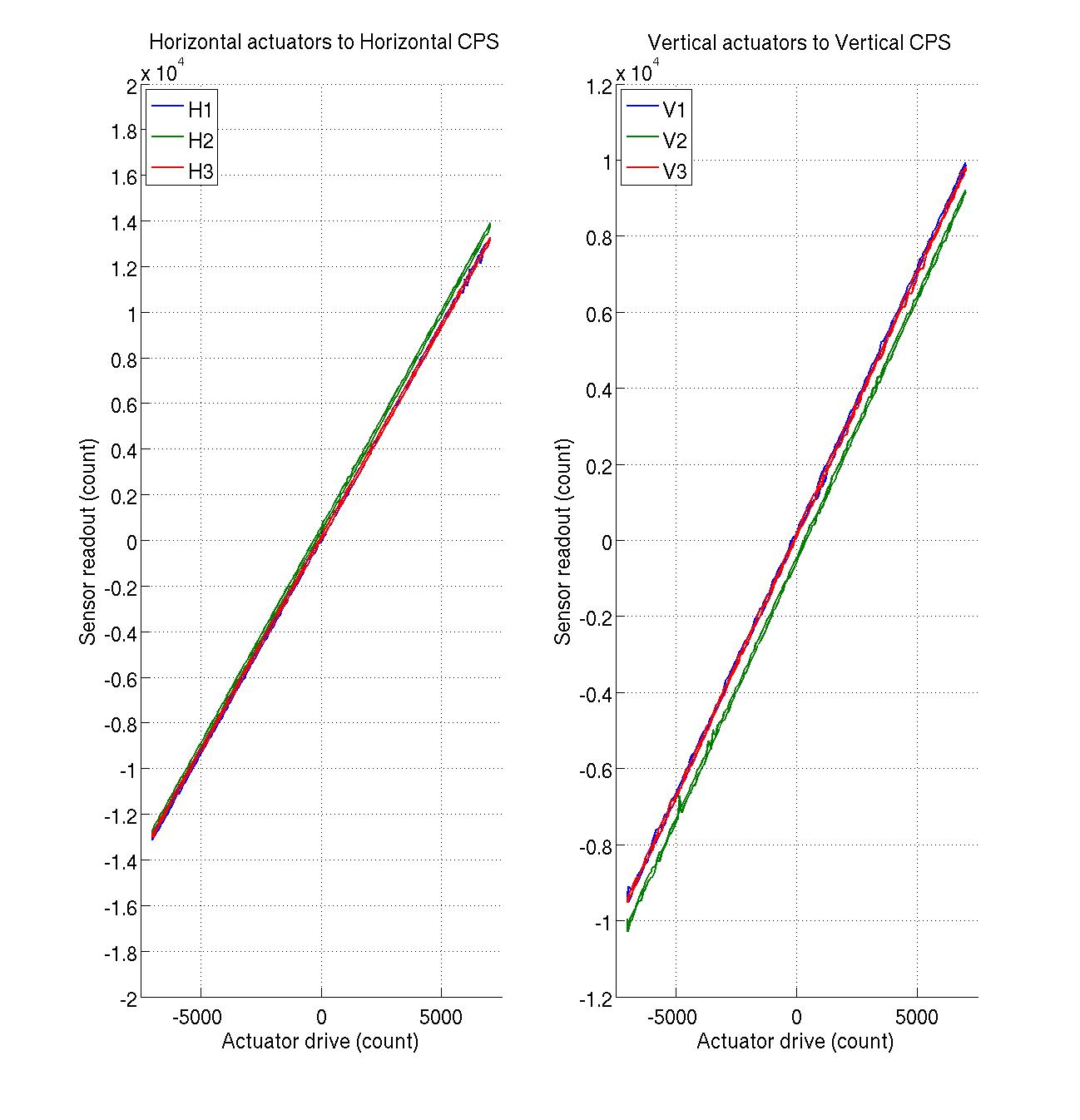
Transfer functions and a linearity tests were measured on HAM3-ISI earlier this week.
The linearity tests looks good. Variations in slope are within requirements.
Transfer functions look good too. Concordance with LLO HAM3-ISI are satisfying. Some noise can be seen in high frequencies on the TFs measured with the vertical GS13s. These sensors saturated a bit during the measurement.
HAM3-ISI has been re-locked, and worked on, since. It is currently locked. We are planning on running a new set of transfer functions, with a slightly lower gain in high frequencies, when HAM3-ISI can be unlocked.
Early this morning, Cheryl check the alignemnt. She found the beam to be:
- good on all three irises before IM1
- misaligned in the FI
- good in the two irises after the faraday (before and after IM4)
All suspension had unchanged offsets wrt yesterday, in particular:
| IM1 | IM2 | IM3 | IM4 | |
| Pit | 1000 | -1750 | 1500 | 0 |
| Yaw | -700 | 0 | 0 | 0 |
She checked again and more thoroughly mid-morning, with the same conclusion. She took some picture (to be posted soon)
HAM3 ISI was then locked, which did not visibly change the beam reaching HAM2. This allowed David and Luke to torque to spec (100 in lb) all clamps on HAM3 ISI: MC2, PR2, all IO components, cable clamps and ISC breadboard to the table (but not the componenets to the breadboard).
HAM3 ISI was then unlocked (again with no visible shift in the beam) and we proceeded to re-aligning the FI, using IM1 and IM2 (only yaw, as pitvh looked good). Then we used IM3 (again, only yaw) to center the beam on the iris between IM3 and IM4. Finally we centered the beam on PR2 using IM4 in both pitch and yaw (we replaced the PRM surrogate with an AR-AR optic with the same wedge and thickness, to increase the visibility of the transmitted baem). Final offsets:
| IM1 | IM2 | IM3 | IM4 | |
| Pit | 1000 | -1750 | 1500 | -1050 |
| Yaw | -1500 | -750 | 500 | 7050 |
And it was lunch time...
After lunch, we placed an iris after the PRM surrogate to be used as a reference for the beam out of IM4, and for red laser alignment. We then removed the yaw offset from IM4, and used the pushers to rotate it back untill the beam was centered again on the iris (about 1/4 mm, or less than half a turn). Other miscellana:
- clamp adapeter and clamp placed on the short east side of MC1
- all non-temporary (and a few temporary) clamps torque to spec (100 in lb): MC1, MC3, IM1-4 (at present, with 2 temporary clamps each), MC refl telescopes, IO telescope, IO steering mirrors.
- visble laser set-up ans aligned to the irises. Form now on we can work in laser safe codnition using the red laser.
I have attached the transfer functions measured on BSC1. They are slightly different (rigid body modes ~5Hz) from those measured at LLO on BSC1 (similar payload) and BSC8 (the same ISI).
LHO BSC1:
https://svn.ligo.caltech.edu/svn/seismic/BSC-ISI/H1/ITMY/Data/Figures/Transfer_Functions/Measurements/Undamped
H1_ISI_ITMY_TF_L2L_Raw_from_ST1_ACT_to_ST1_CPS_2012_12_04.fig
H1_ISI_ITMY_TF_L2L_Raw_from_ST1_ACT_to_ST1_L4C_2012_12_04.fig
H1_ISI_ITMY_TF_L2L_Raw_from_ST1_ACT_to_ST1_T240_2012_12_04.fig
H1_ISI_ITMY_TF_L2L_Raw_from_ST2_ACT_to_ST2_CPS_2012_12_04.fig
H1_ISI_ITMY_TF_L2L_Raw_from_ST2_ACT_to_ST2_GS13_2012_12_04.fig
LLO BSC1:
https://svn.ligo.caltech.edu/svn/seismic/BSC-ISI/L1/ITMY/Data/Figures/Transfer_Functions/Measurements/Undamped
LLO_ISI_BSC1_TF_L2L_Raw_from_ST1_ACT_to_ST1_CPS_2012_11_07.fig
LLO_ISI_BSC1_TF_L2L_Raw_from_ST1_ACT_to_ST1_L4C_2012_11_07.fig
LLO_ISI_BSC1_TF_L2L_Raw_from_ST2_ACT_to_ST2_CPS_2012_11_07.fig
LLO_ISI_BSC1_TF_L2L_Raw_from_ST2_ACT_to_ST2_GS13_2012_11_07.fig
LHO BSC8:
https://svn.ligo.caltech.edu/svn/seismic/BSC-ISI/H2/ITMY/Data/Figures/Transfer_Functions/Measurements/Undamped/
LHO_ISI_BSC8_TF_L2L_Raw_from_ST1_ACT_to_ST1_CPS_2012_05_21.fig
LHO_ISI_BSC8_TF_L2L_Raw_from_ST1_ACT_to_ST1_L4C_2012_05_21.fig
LHO_ISI_BSC8_TF_L2L_Raw_from_ST2_ACT_to_ST2_CPS_2012_05_21.fig
LHO_ISI_BSC8_TF_L2L_Raw_from_ST2_ACT_to_ST2_GS13_2012_05_21.fig
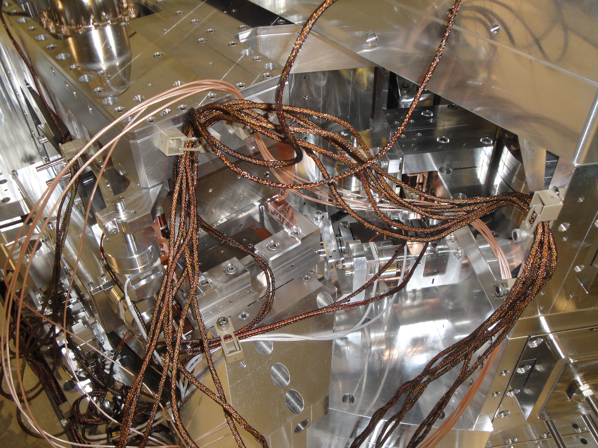
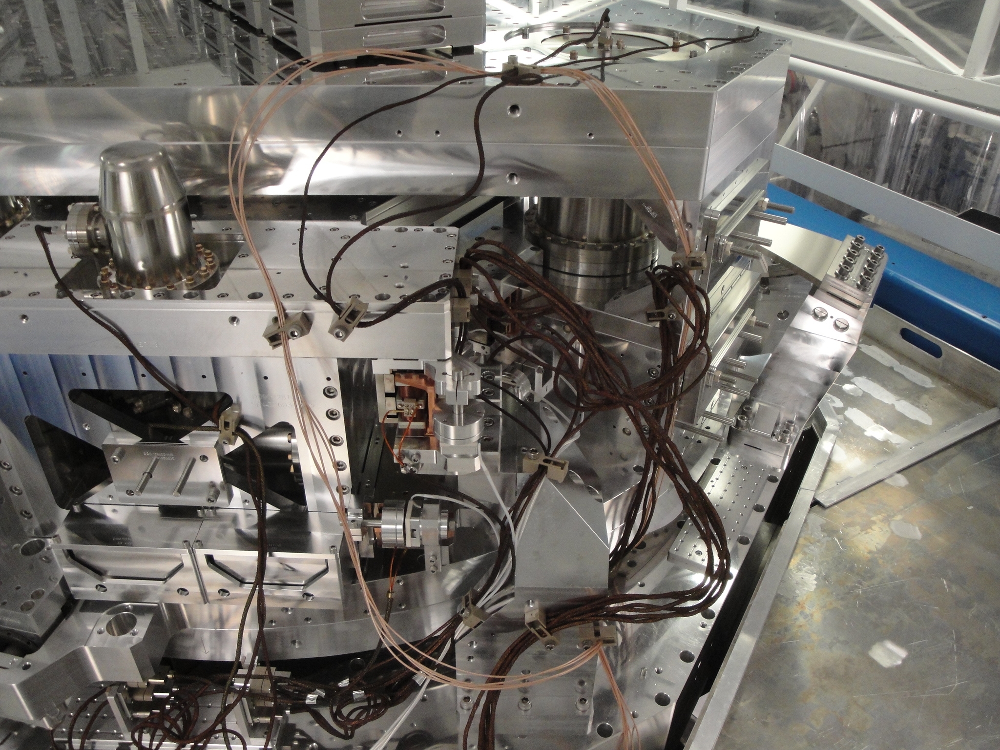
There were some oddities in the transfer functions Vincent collected so we went to the ISI.  Corners 1 and 2 looked pretty good but Corner 3 never does.  So we reworked it some to hopefully improve the results--yet to be determined.
A couple before and after images not all that revealing.  It is obvious we did something but not that obvious in the photos that it is better--you gotta be there!
EX
In-chamber cleaning continues
New HVAC system for the Lab is now online after being serviced today
BSC1
Hugh & Vincent worked on/around cabling up on the BSC-ISI to troubleshoot some noise on the BSC-ISI
IO Work
The team planned on checking torque-ing for MC2 (requiring HAM3 ISI to be locked), and alignment work continues (so we've remained in Laser HAZARD all day)
Rest of Day's Activity
We air brushed lower sections 1,2,3,&4 and floor sections 1,2,&3. We also completed the hand brushing on the fins. Stand down on ICC for the day to torque bolts on HAMs 4&5 doors.
The dust monitor at location 8 in the LVEA, labeled S, gave a calibration warning and was turned off. This was in the small clean room between HAM 2 and 3 with the auxiliary optics. Today I removed the dust monitor at location 1 in the end Y VEA labeled L and replaced S with it.
Attached are plots of dust counts > .3 microns and > .5 microns in particles per cubic foot from approximately 6 PM Dec. 5 to 6 PM Dec. 6. Also attached are plots of the modes to show when they were running/acquiring data.
Brushed with drills all sections from bottom of collar to floor and began hand brushing fins yesterday.
[David, Rodica, Luke, Giacomo]
After the HAM3 ISI was unlocked this morning, we verified that the table moved small enough that the MC was still flashing.
We then verified the alignment through the HAUX and FI up to IM4, that was still good.
We prepared two iririses at the the nominal height of the beam on the table, placed them before and after IM4 and aligned them to the IR beam to serve as references for the visible laser we will be using for alignment of the auxiliary optics. However, we then realized that IM4 only "nominally" aligned in both pitch and yaw, so this will need to be tweaked tomorrow.
After that, we aligned the REFL beam to the input beam using the PRM surrogate, and the backward rejected beam to the HAM1/2 viewport; we then measured the input beam power (505 uW), and tried to measure the power in the backward beam reflected off of MC3, but we could not distinguish it from the background. Based on the uncertainty on the background measurement (25 nW) we estimated an isolation ratio > 40 db.
Finally, we measured the power in various location of the forward beam (in uW +- 1 uW):
after MC3 = 524
after IM1 = 504
after IM2 = 505
after IM3 = 494
after IM4 = 494
after PRM sur = 15
This yield a 96.2% transmission through IM1 (but we have the wrong polarization), a 97.8% combined "transmission through FI and reflection off of IM3" (although reflection through IM3 should be basically 100%, as it is in the right polarization) and a 3% (as expected) transmission thorugh the PRM surrogate.
Based on these numbers, the REFL beam at at the HAM1/2 septum viewport should be 469 +- 5 uW. We measured 466 uW: apparently we didn't loose any beam on the way... :-)
Attached are plots of dust counts > .3 microns and > .5 microns in particles per cubic foot from approximately 6 PM Dec. 4 to 6 PM Dec. 5. Also attached are plots of the modes to show when they were running/acquiring data.
we just got an alarm on the diode room overtemp. Looking at a trend, it appears the room temperature started fluctuating at 4am this morning, and recently got very cold, and the heated up to the alarm point at 70F. It is cooling down at the moment. Michael was notified, he will take a look at it tomorrow.
- Cabling around BSC1
- IO work in HAM2
- SEI work on HAM3
- Changes to BSC1 IOP watchdogs
- Low battery on Mid-X fire panel
- Reboots of the OPS machine to restore both screens
(Corey, Keita)
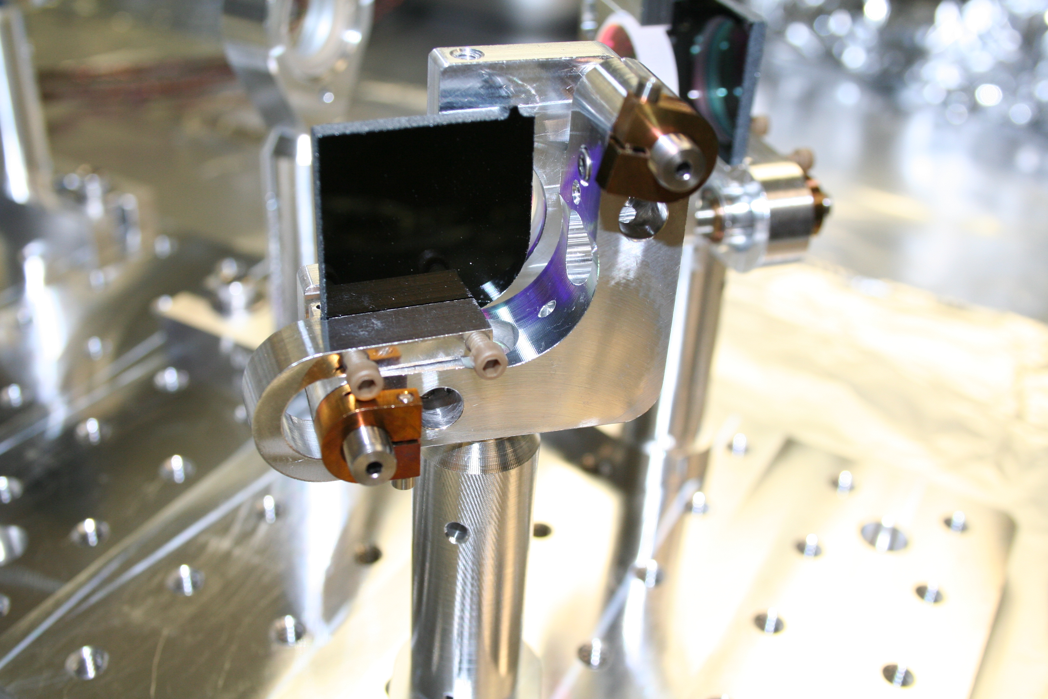
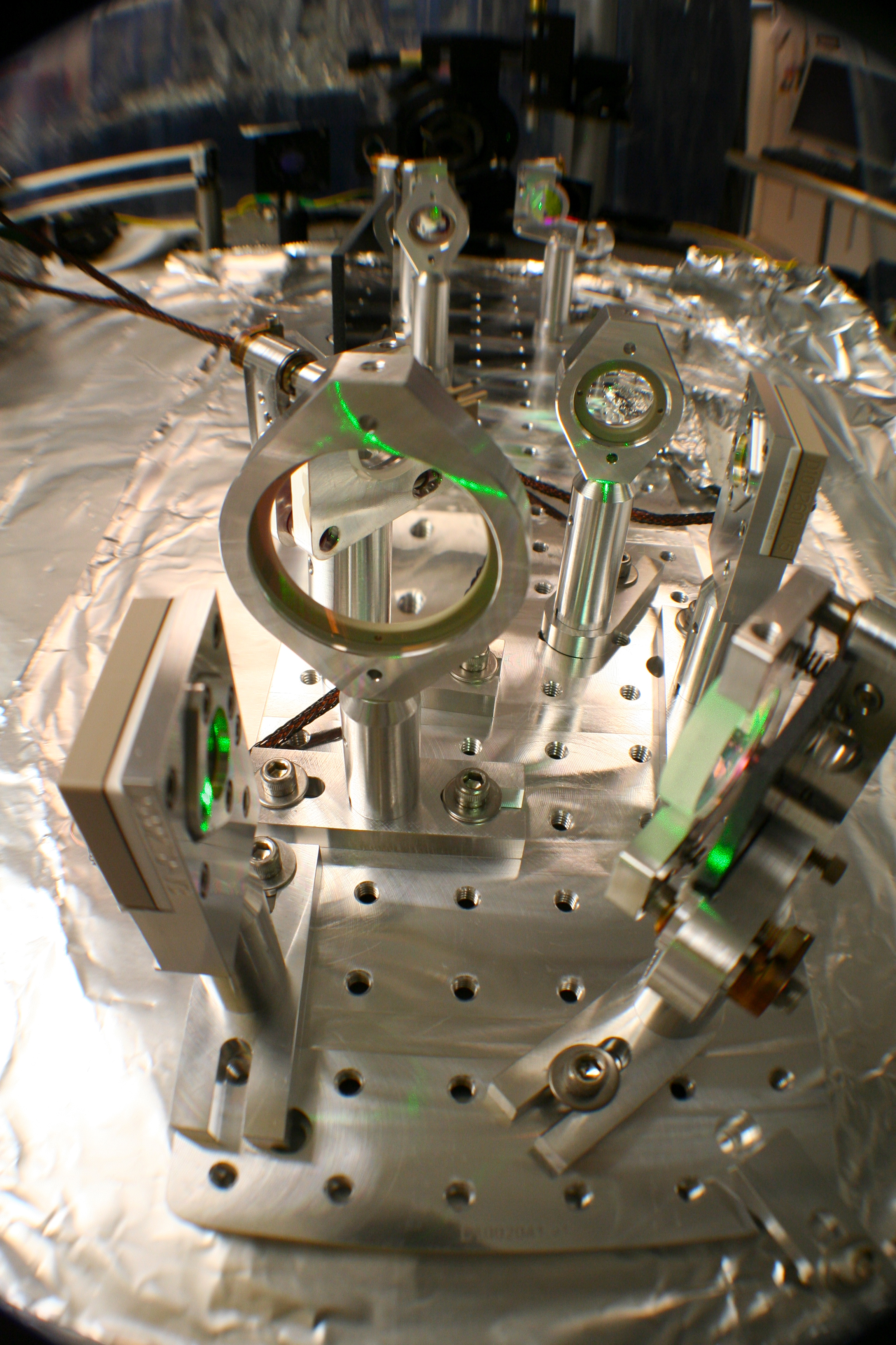
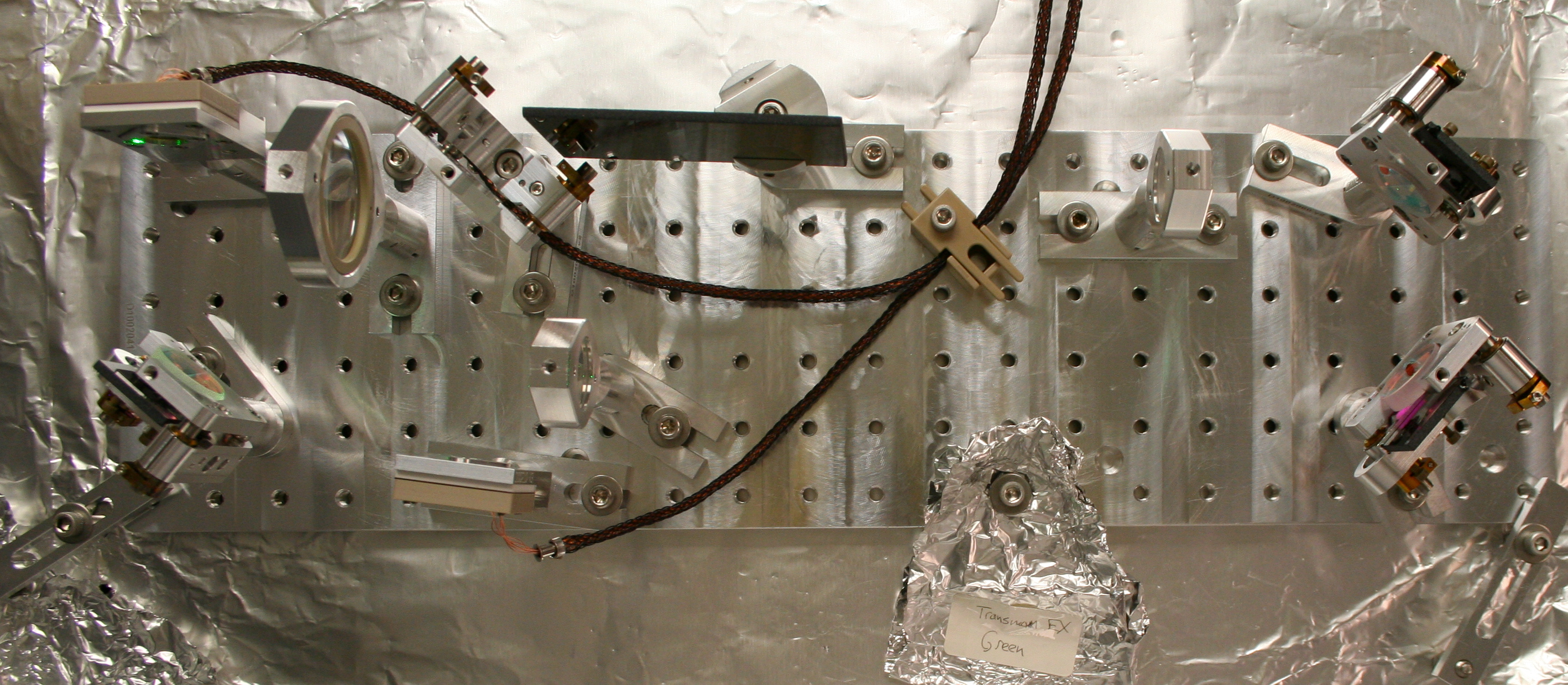
My mode-matching lessons from master Jedi Kawabe continue with the building of the EX Green QPD Sled. This Sled is one of two on EACH Transmission Monitor Suspension (TMS); the other is an IR QPD Sled (to be assembled next). We actually built this Sled twice. After completing it the first time, Keita noticed, "this sled looks like EY. It's supposed to be a mirror image!" It was all a learning experience. So, we ended up re-building the sled (it went much quicker since we, in essence, already had an assembly dry run).
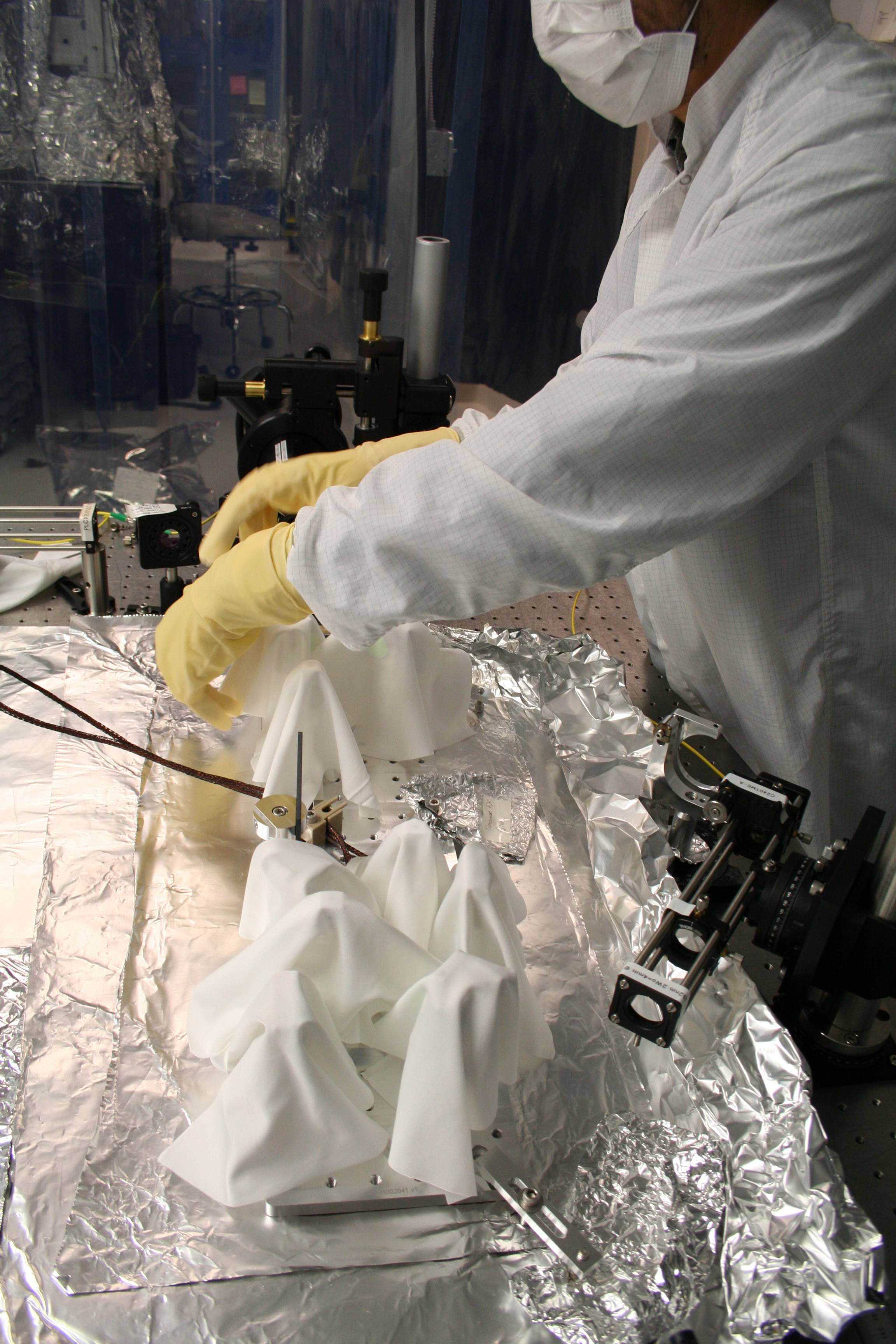
Once the Sled was completed, we draped wipes over all optical components, wrapped the entire assembly in foil, double-bagged it, and placed the entire thing in a large plastic bin for storage under our Optics Table in the Optics Lab (the HAM1WFS Sled is also stored here).
Keita has plots and data from our mode matching measurements and will post a more thorough document about our EX Green Sled work to the DCC.
Note: The "J-Clip" Black Glass Beam Dumps on our Steering Mirrors are tough to install. There's a screw on the mount which interferes with the J-Clip and makes installing/removing these parts tough.
I have uploaded all photos for this EX Green Sled on ResourceSpace, here.
Forgot to measure distance between optical components on this Sled, so it was opened up and these measurements were made.
For measurements below, the lenses are measured on the "backface" of their Lens Holder. The Mirrors & Beam Splitters are measured from their glass "front faces". The QPDs are measured from the QPD Housing plate (D1002110). Measurements were measured with a scale & all measurements are in mm.
Was considering changing from STEP to FIXED (5000V) voltage but didn't
WP 3589
I modified the IOP model for the BSC1 SEI system (h1seib1) to permit up to 10 IPC receive errors per second from the h1iopsusb123 sender (SUS ITMY). We are currently experiencing about 5 errors per day on this Dolphin link, we currently dont know what the problem is. We hope the upgrade to RCG2.6 will resolve this issue.
I did a cursory test of the IPC watchdog by PANICing the SUSB123 DACKILL and verifying that the SEIB1 tripped. It is not possible to test that an error rate of >10 will trip SEIB1 without rebooting the SUSB123 and possibly disrupting the mode cleaner work.
We had a single IPC error this afternoon and the SEIB1 IOP ran through it without DACKILL'ing the ISI. So far, so good.
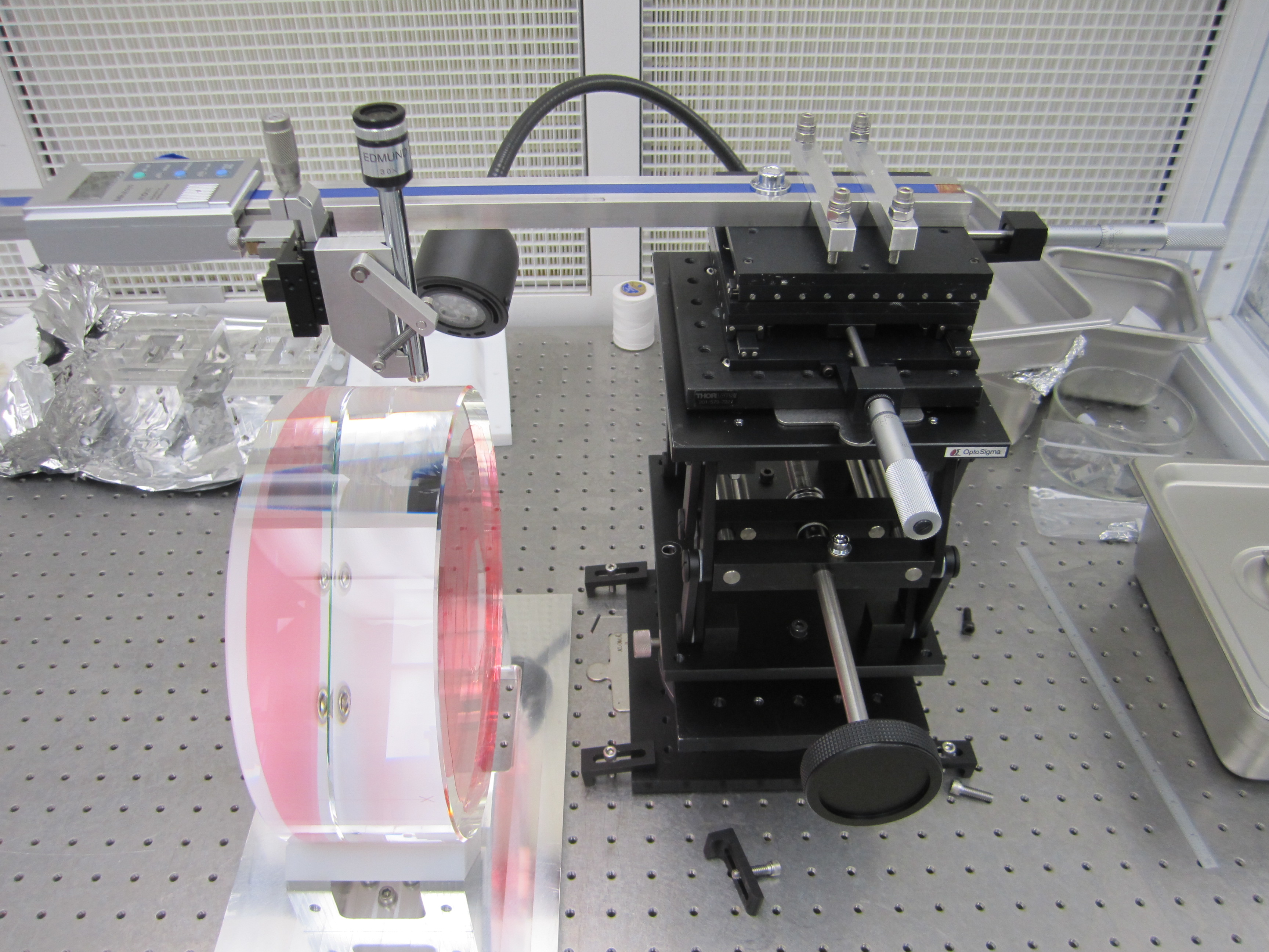
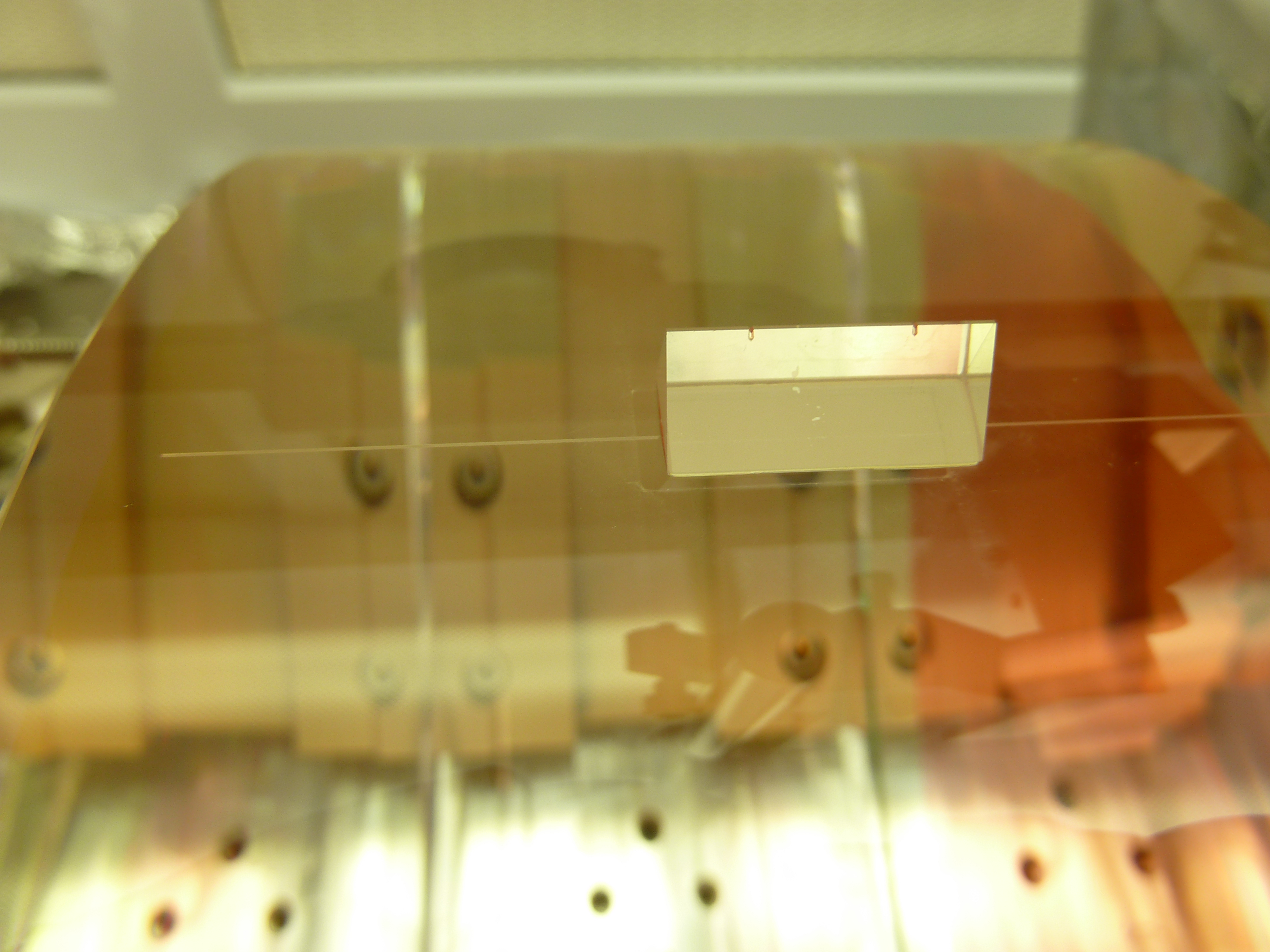
Yesterday I spent the day rebuilding the HXTS prism gluing measurement apparatus in order to accomodate the HLTS sized optic. At the end of the day I finally glued the prism on. Today, Gerardo removed the fixturing and sees that the prism is 2mm out of spec in the pitch-direction. Ugh. The d-value direction (or distance up from the scribe line) has been corrected. Both of these dimension differences from the first round of gluing can be seen in the attached picture where the phantom footprint from the last glued on prism was. The new prism should line up with the phantom line on the left end of the prism, but should remain at the current horizontal position on the line. I estimate that this error would induce roughly ~40mRad of pitch error. Because this glue bond is still somewhat fresh (only an overnight room temp cure) and the position error is so large, Gerardo is placing the prism down into an acetone bath for the night to remove it.
Mulligan-again for tomorrow.
It is unfortunate that you cannot check any of the setup measurements once the prism is in the fixture and glued down. We *think* this happened because the measurement apparatus is not very good at staying alignment when traveling up and down (away from the optic) in order to adjust for focus. You focus on the scribe line on the optic during setup and then you must slide up to focus on the notches on the prism which are many mm of focus different. Likely this focal plane change has some sideshift (on the order of the 2mm error we now see). I'm not sure what a good fix for this is this. I'll try removing some of the brackets between the traveling bore-scope and the horizontally mounted height guage.
Playing with the measurement apparatus today, Gerardo and I discovered that the bore scope 1) wobbles up and down relative to g, and 2) runs downhill by ~3mm over a 300mm length due to the weight if itself hanging off the end of the horizontally mounted height guage (see pic attached). Both piggy-backed jacks have slop in this direction. I can remedy 2) via shimming the entire stack of joints, but I'm not likely to be able to improve 1) without rearranging the entire measurement motivation. Hopefully 2) was the larger contributor to Monday's error. The top portion of the apparatus is the same as what I used to glue prisms to MC2 and PR2, so we would have see some slop then as well, however since the optics were smaller, the travel (and subsequent shifting of load) must have been less noticeable.
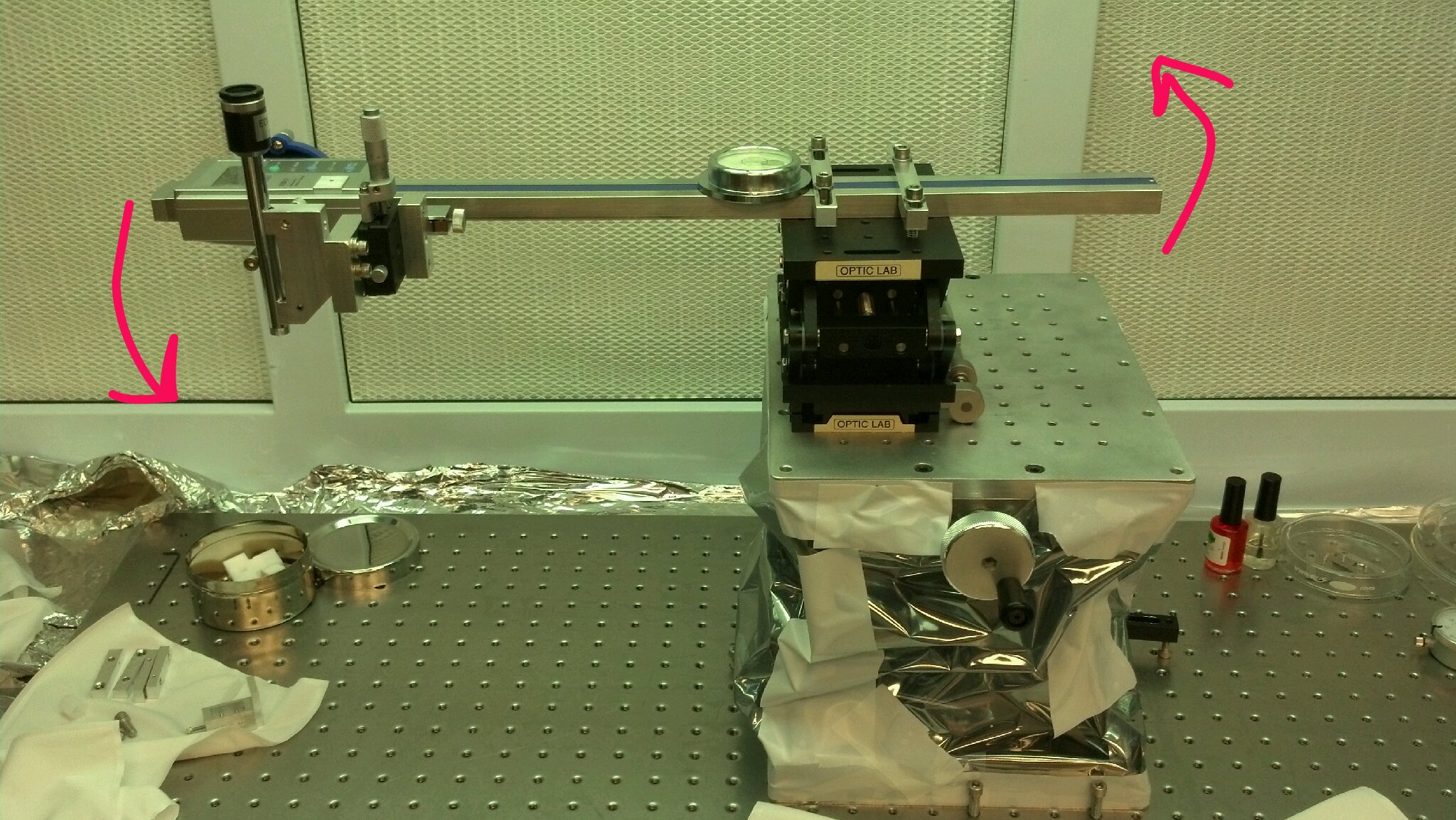
Attached is the LLO gluing apparatus, shown with an HLTS optic. It also is stacked lab jacks.