Displaying reports 81301-81320 of 83283.Go to page Start 4062 4063 4064 4065 4066 4067 4068 4069 4070 End
Reports until 09:39, Tuesday 17 January 2012
H2 SEI
greg.grabeel@LIGO.ORG - posted 09:39, Tuesday 17 January 2012 (2052)
HAM2 HEPI Install

aLIGO HAM 2 has had the old iLIGO stacks removed and replaced with fancy new HEPI piers, frames, and crossbeams. The support tube positions will be checked and fine tuned within the week. Hopefully work can begin on removing the iLIGO HAM 3 stacks and installing the new HEPI structures soon.

Images attached to this report
H2 CDS
james.batch@LIGO.ORG - posted 09:03, Tuesday 17 January 2012 (2051)
New Version of Awgstream installed for Linux Workstations
A new version of awgstream has been installed for Ubuntu workstations which corrects a bug in which not all channel names are read from the nds.  New version is 2.15.5. 
H2 SUS
betsy.weaver@LIGO.ORG - posted 17:42, Monday 16 January 2012 (2050)
ETMy QUAD misc failures
While working on the ETMy today, we also found that one of the 4 PUM flags had a failed glue joint, and one of the PenRe AOSEMs has a broken PD filter.  We reglued the flag and set the heat lamp for overnight.  We'll need to get a replacement AOSEM to swap with the one with the broken filter.
Images attached to this report
H2 SUS
jason.oberling@LIGO.ORG - posted 16:00, Monday 16 January 2012 - last comment - 17:23, Monday 16 January 2012(2048)
ERM Pitch and ETM Vertical Position Measurements

J. Oberling, B. Bland, T. Sadecki

Betsy noted that a cable was rubbing on the side of the LSAT and that this cable was influencing pitch.  She corrected this and I measured the ERM pitch in the single, double and triple hang configurations:

Betsy then put the reaction chain in the double hang configuration and adjusted the pitch to 1.21 mrad down.  I then measured the ERM triple hang pitch again:

This was deemed acceptable for ERM pitch adjustments on the LSAT.

Travis made adjustments to the main chain to lower the ETMy in the quad assembly, then I measured the ETMy roll and vertical position.  Roll is reported as the vertical distance from the ETMy horizontal centerline (measured with an optical level and a scale attached to a carbon fiber rod hanging from the ISI optics table) and vertical position was measured as done on 1-13-2012.

Comments related to this report
betsy.weaver@LIGO.ORG - 17:23, Monday 16 January 2012 (2049)
Pictures attached: The cable interference in the Lower Structure Tooling (LSAT) and then after I unlaced the cable and stuffed it up on the UIM.  I'm not sure how it was envisioned that we use this tooling with cables - this is the first time it has been tried and it's proving to be more work that anticipated.  Likely the cable bundling (the fix) in the tooling still affects the pitch, which will change when we restore the cabling back to it's nominal routing.  So, while we gave up at 2mRad, we know we can get the pitch error smaller in the full hang on the ISI.
Images attached to this comment
H2 SEI
hugh.radkins@LIGO.ORG - posted 17:49, Friday 13 January 2012 - last comment - 13:17, Tuesday 17 January 2012(2044)
BSC8 SEI Stage0 Modified to SUpport ACB Install
JimW, ScottS, Hugh

See the attached which is a zoom in of D0900894 sht2.  The upper right cloud area is the SW corner of the SEI ISI Stage0(+Y,-X) looking up.

We tapped and helicoiled the three holes in the right cloud and one of the 'A' holes in the left (not exactly sure which) to accommodate the planned mounting of the ACB dog clamp and alignment pushers.  These holes were vent holes and were never planned to be tapped.  We were lucky in that they were close enough in size to only lose maybe 25% of the thread holding in the aluminum--plenty fine for the 200lb ACB.
The story is this clamp and these pushers can be removed as there is another clamp on the mounting plate.  And we could swap out the hardware later with vented bolts.
Non-image files attached to this report
Comments related to this report
hugh.radkins@LIGO.ORG - 13:17, Tuesday 17 January 2012 (2056)
Below is Actual entry before system logged me off and I thought all was lost.  Jonathan showed me the drafts and it was saved there.  Thanks!


The Arm Cavity Baffle crew this morning reported holes that were not tapped/helicoiled for the dog clamp & pusher attachment.  These were in the bottom of Stage0.  See D0900894 if you want to follow along or see the attached.

On the attached drawing, I've zoomed in and highlighted the areas of interest.  The cloud circled area to the right is the SW corner(+Y,-X) of the SEI Stage0 looking up.  This is grid area H6 of Sheet 2 of D0900894.  The three holes in vertical alignment on the left with the center one labeled A and the other two unlabeled are the three holes that were planned to connect a custom dog clamp to Stage0.  Problem is only holes marked C are actually tapped and helicoiled for use.  The 'A' hole is the bottom thru vent for the 1/2-13 Stage0 Bottom/Top clamping bolts.  The unmarked holes are the '2' holes called out on sheet 3.  These are fully thru Stage0 Bottom venting the 5/8-11 bolts clamping the Stage0 Spring Post to the Stage0 Top along with a few other things.  The right most 'A' hole in the cloud area was planned to be used with the lower 'C' hole to clamp on an ACB alignment pusher.
On the left side of my zoom-in drawing in the ellipse highlight area, one of the outboard 'A' holes (not sure which) was planned to mount the other pusher in combination with a 'C' hole.

We got very lucky.  Both the A & 2 holes were drilled 0.41" and are plenty deep (inches).  The drill diameter for a 3/8-16 helicoil tap is 0.397".  So we started with a hole 13mils oversized.  The helicoil OD is 0.450".  So we lost 13 of 53mils (assuming the helicoil diameter is the tap OD, which it likely isn't.)  Still we assumed this and figured we lost some 25% of the nominal thread holding in the Stage0 Aluminum.  Since the ACB weighs less than 200 lbs, any one of these even weakened holes can likely hold the entire ACB and it will actually be held by at least four.  So we went to John Worden with this info and he gave us approval to use these thru/vent holes.

So we tapped the 4 holes on the right and 1 on the left for 3/8-16 2D helicoils.  We did this in-situ holding a chip catch under the tap.  I can't lie, I'm sure there are some tap chips that made it under the flooring of the BSC but we did the best we could to catch all the chips.  We swapped out our chip catch for each hole and had no spills.  As the hole was oversized, the tapping wasn't too bad and we flushed the hole with IPA again catching the effluent.  We then ran the cleaned tap into the hole again, flushed the hole again, and then inserted the helicoil.  We tested the holes and then mounted the Pushers.  The right middle 'A' hole must have gotten a little chip under the helicoil but the bolt wasn't too bad going in--it starts fine and threads a few turns before tightening up for just a little bit, then it is fine.

Finally--These vent holes are now not vented and there is a fairly large trapped volume--~20"x.41dia.  Fortunately, the pushers AND the right clamp can come off as there is another clamp in the middle.  And we have a chance to get vented bolts and replace them if needed.
LHO General
patrick.thomas@LIGO.ORG - posted 17:13, Friday 13 January 2012 (2042)
plots of dust counts
Attached are plots of dust counts > .5 microns.
Non-image files attached to this report
H1 AOS
michael.rodruck@LIGO.ORG - posted 17:03, Friday 13 January 2012 (2041)
Water filters swapped

Rick S, Michael R

Water filters for the chilled water lines were swapped out today. This includes the small filter located inside the diode chiller itself. The old filters looked pretty ugly, pictures are attached. We threw in a new unused filter in the photo to show the difference between clean and dirty. We can still see gold flecks in the crystal chiller's new filter.

New flow rates

Crystal chiller: 16 lpm

Diode chiller: 28.3 lpm

Images attached to this report
H1 PSL
michael.rodruck@LIGO.ORG - posted 16:48, Friday 13 January 2012 (2040)
H1 PSL installation

Michael R, Bubba G, Robert S

Table was set in place today. Tuesday we will have contractors out to start construction of the acoustic enclosure.

The table top has been fully cleaned and is covered in ameristat.

Images attached to this report
H2 SUS
travis.sadecki@LIGO.ORG - posted 16:31, Friday 13 January 2012 - last comment - 10:04, Tuesday 24 January 2012(2039)
Status of SUS in BSC8

After the ACB crew had finished their work in BSC8, I entered the chamber to unlock FMy.  So, until further update, the status of the suspensions is: ITMy is LOCKED, FMy is UNLOCKED.  I'll leave it to the ACB and SEI crews to independently report their status.

Comments related to this report
travis.sadecki@LIGO.ORG - 10:04, Tuesday 24 January 2012 (2076)

As of 19th Jan., both ITMy and FMy are UNLOCKED.  ITMy is aligned to IAS specs.  Some further adjustments to the OSEMs are coming soon to finalize these suspensions. 

H2 SUS
jason.oberling@LIGO.ORG - posted 16:26, Friday 13 January 2012 (2038)
ERM Pitch Measurements

J. Oberling, T. Sadecki

Set up the LSAT for the ERM at End Y this afternoon: leveled the LSAT structure and the Reaction Chain (RC) lower structure using an optical level.  We then looked at both the double-hang and triple hang pitch of the ERM:

H1 AOS
keita.kawabe@LIGO.ORG - posted 16:24, Friday 13 January 2012 - last comment - 18:33, Sunday 15 January 2012(2037)
H1 HAM4 optics deinstall (DavidJ, JohnM, Corey, Sheila, Keita)

We uninstalled everything on HAM4.

The followings were bagged and labeled for later reuse for aLIGO itself as well as aLIGO related researches at here and elsewhere:

These are all stored in plastic bins and are temporarily put in the ALS/SQZ work area.

There was a mirror-like thing mounted on one of the side viewports from inside. What is this? It was bagged, but if there's no taker I'll throw it away.

The beam reducing telescopes were roughly wrapped with foils and left in the clean room. Store them wherever you want.

All counter balance masses will go to the recycle bin.

HAM5 baffles was not removed this time.

Corey will post pictures, Sheila will notify Carolyn which iLIGO parts are kept.

Comments related to this report
corey.gray@LIGO.ORG - 18:33, Sunday 15 January 2012 (2047)

Attached are some photos from the work Keita mentions above.

Link to all full-sized photos from the HAM4 Extract are located here:

https://ligoimages.mit.edu/?c=919

Images attached to this comment
H2 SUS
jason.oberling@LIGO.ORG - posted 13:33, Friday 13 January 2012 (2036)
Initial ETMy Pitch and Vertical Position Measurements

J. Oberling

At Betsy's request, I measured the pitch and the vertical position of the ETMy as a check of where the ETM is sitting with respect to the ideal vertical position (1742mm from the ISI optics table).  Pitch was measured to ensure a gross pitch error was not causing the appearance of the ETMy sitting in the wrong vertical position.

To measure the vertical position I used the total station to measure the elevation angles required to sight the top and bottom edges of the ETMy.  The tangent of the angle is multiplied by the distance from the total station to the optic to give the vertical distance from the ideal center, as established by the total station, to the respective edge of the ETMy.  To get the distance to the ETMy I used the total station's Electronc Distance Measurement (EDM) feature, which has the ability to measure a distance without using a corner cube prism (the reflectorless EDM has a 3mm error bar).  I sighted the right side of the quad cage, in the recessed portion and measured the distance; this distance was then multiplied by the cosine of the azimuth angle to sight the quad cage to give the distance from the total station to the ETMy.  This is not ideal and does introduce error into the vertical position measurement, not only due to the 3mm error bar of the reflectorless EDM but also due to the fact that the HR surface of the ETMy does not align to the recessed surface of the quad cage but is actually several mm behind it (I assume the ETMy HR surface is within 10mm of the recessed surface), but will give a general idea of where the ETMy is with respect to the ideal vertical position (when measuring a distance of ~7m, a change of 10mm in either direction only results in a change of the vertical distance from ideal center to ETMy edge of ~0.3mm).  The distance from the ideal center to the top and bottom edges should be 170mm (the radius of the ETMy).

The result here is that the measured pitch of 2.02 mrad is not enough to cause the ETM to appear to be sitting ~2.9mm too high in the quad assembly, therefore the ETMy is actually sitting ~2.9mm too high in the quad assembly.

H2 SEI
vincent.lhuillier@LIGO.ORG - posted 11:06, Friday 13 January 2012 (2035)
ISI-BSC8 Tests

We took a first set of transfer functions (Local to Local) between 10Hz and 1000Hz (without baffle – No TMD – No vibration absorbers – No Viton pads under the keel masses - ITMY and FMY damped). After comparing with the measurements before the cartridge install, we can notice:

-          No extra resonance created by the HEPI Post between 10Hz and 1KHz (ST1 CPS transfer functions). Obviously, the resonances of the teststand are not visible anymore (first resonance at 19Hz).

-          First resonance of stage 1 is 217Hz (it will be damped by the vibration absorbers on the door of stage 1)

-          Second resonance observed on stage 1 at ~250 Hz (blade 0-1). The HAM-ISI TMDs retuned for BSC-ISI (E1100963-v1) will be later installed.

-          New resonances in the stage 2 transfer functions (53Hz). It is most visible in the Cartesian to Cartesian transfer functions.

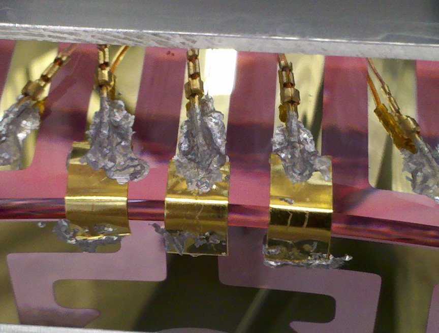
The vibration absorbers were installed on the 3 doors of stage 1 (2 per doors). For the first test, masses are resting on 4 Viton pads (0.25”x0.25”x.0125”) and the lid is not added. Transfer functions show a reduction of the resonance at 214Hz by a factor of 6 in the X, Y, RX, RY. Tests with differentpads will be performed when the ISI will be available.


Reference Transfer functions (L2L) without baffle – No TMD – No vibration absorbers – No Viton under the keel masses - ITMY and FMY damped

In the local basis

seismic/BSC-ISI/H2/ITMY/Data/Figures/Transfer_Functions/Measurements/Comparison/

LHO_ISI_BSC8_Comparison_TF_L2L_ST1_ACT_H_to_ST1_CPS_H_20111206_vs_20120106.fig
LHO_ISI_BSC8_Comparison_TF_L2L_ST1_ACT_V_to_ST1_CPS_V_20111206_vs_20120106.fig
LHO_ISI_BSC8_Comparison_TF_L2L_ST1_ACT_H_to_ST1_L4C_H_20111206_vs_20120106.fig
LHO_ISI_BSC8_Comparison_TF_L2L_ST1_ACT_V_to_ST1_L4C_V_20111206_vs_20120106.fig
LHO_ISI_BSC8_Comparison_TF_L2L_ST2_ACT_H_to_ST2_CPS_H_20111206_vs_20120106.fig
LHO_ISI_BSC8_Comparison_TF_L2L_ST2_ACT_V_to_ST2_CPS_V_20111206_vs_20120106.fig
LHO_ISI_BSC8_Comparison_TF_L2L_ST2_ACT_H_to_ST2_GS13_H_20111206_vs_20120106.fig
LHO_ISI_BSC8_Comparison_TF_L2L_ST2_ACT_V_to_ST2_GS13_V_20111206_vs_20120106.fig


In the Cartesian basis – Recomputed from Local measurements:

seismic/BSC-ISI/H2/ITMY/Data/Figures/Transfer_Functions/Measurements/Comparison/

LHO_ISI_BSC8_Comparison_TF_C2C_ST1_ACT_H_to_ST1_CPS_H_20111206_vs_20120106.fig
LHO_ISI_BSC8_Comparison_TF_C2C_ST1_ACT_V_to_ST1_CPS_V_20111206_vs_20120106.fig
LHO_ISI_BSC8_Comparison_TF_C2C_ST1_ACT_H_to_ST1_L4C_H_20111206_vs_20120106.fig
LHO_ISI_BSC8_Comparison_TF_C2C_ST1_ACT_V_to_ST1_L4C_V_20111206_vs_20120106.fig
LHO_ISI_BSC8_Comparison_TF_C2C_ST2_ACT_H_to_ST2_CPS_H_20111206_vs_20120106.fig
LHO_ISI_BSC8_Comparison_TF_C2C_ST2_ACT_V_to_ST2_CPS_V_20111206_vs_20120106.fig
LHO_ISI_BSC8_Comparison_TF_C2C_ST2_ACT_H_to_ST2_GS13_H_20111206_vs_20120106.fig
LHO_ISI_BSC8_Comparison_TF_C2C_ST2_ACT_V_to_ST2_GS13_V_20111206_vs_20120106.fig

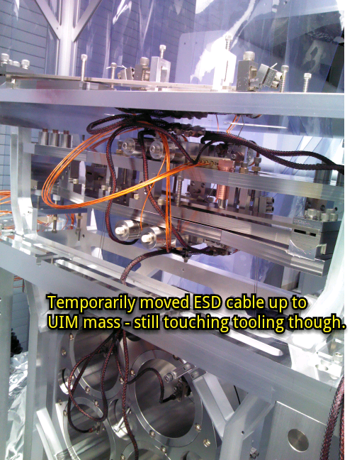
Transfer functions L2L without baffle – No TMD – Vibration absorbers (0.25”x0.25”x0.125”) – no lid (cables touching the mass of the 2x1 vibration absorbers in corner ) – No Viton under the keel masses - ITMY and FMY damped:

seismic/BSC-ISI/H2/ITMY/Data/Figures/Transfer_Functions/Measurements/Comparison/

LHO_ISI_BSC8_Comparison_TF_C2C_ST1_ACT_H_to_ST1_CPS_H_20120106_vs_20120110.fig
LHO_ISI_BSC8_Comparison_TF_C2C_ST1_ACT_V_to_ST1_CPS_V_20120106_vs_20120110.fig
LHO_ISI_BSC8_Comparison_TF_C2C_ST1_ACT_H_to_ST1_L4C_H_20120106_vs_20120110.fig
LHO_ISI_BSC8_Comparison_TF_C2C_ST1_ACT_V_to_ST1_L4C_V_20120106_vs_20120110.fig


H2 SEI
vincent.lhuillier@LIGO.ORG - posted 10:34, Friday 13 January 2012 (2034)
HEPI BSC8

This week at BSC8, the actuators were connected to the boots. We started to test the HEPI. First, we had to change a horizontal L4C in corner 2 (bad behavior at low frequency). We replaced L41375 by L41499. ASDs confirmed that this new geophone is working fine

After few static tests, we quickly found that the displacement created by the horizontal actuators in corner 2 is not as large as displacements created by the other horizontal actuators (verified with the dial indicators and the IPS). We checked the stops and nothing seemed to be touching. Then, we performed the linearity-hysteresis test for all 8 actuators (attached plots. SUS watchdogs tripped during the measurements – Visible on V3). The plots confirm that there is a trouble in the horizontal direction in corner 2. We are investigating.

Non-image files attached to this report
LHO General
patrick.thomas@LIGO.ORG - posted 19:10, Thursday 12 January 2012 (2033)
plots of dust counts
Attached are plots of dust counts > .5 microns.
Non-image files attached to this report
LHO General
patrick.thomas@LIGO.ORG - posted 19:09, Thursday 12 January 2012 (2032)
dust monitor in clean room over BSC8
The dust monitor in the clean room over BSC8 lost power. It was swapped with the one it replaced and connected to a different break-out box with a different cable today. I do not believe the readings for it (H0:PEM-LVEA_DST15) are valid until after 15:00 local time today.
H2 SUS
betsy.weaver@LIGO.ORG - posted 16:15, Thursday 12 January 2012 - last comment - 23:08, Friday 13 January 2012(2028)
H2 ETMy ERM soldered pins
Today, when we stuffed the ERM mass into the ETMy lower suspension, we noticed that one of the 5 pins had been somewhat dislodged from it's soldering pool on the gold tab.  Gerardo and Margot believe that this is from the "flipping fixture" which is used to handle the mass.  The fixture apparently sits across some or all of these solder joints.  In the picture attached, the pin is the one towards the 4th one from the right.  
Long story short, Margot thinks we need to revisit the soldering of this pin. 
...to be continued.
Images attached to this report
Comments related to this report
betsy.weaver@LIGO.ORG - 23:08, Friday 13 January 2012 (2045)
This morning, Margot and Gerardo reheated the soldering joints of the ETMy ERM ESD pins to reseat them.  I used the cleanroom vacuum to help pull away any vapors, etc, but it was a pretty straight-forward procedure.  Gerardo held the pins with tweezers.  No additional soldering material was added.
Images attached to this comment
H1 COC
betsy.weaver@LIGO.ORG - posted 15:32, Wednesday 11 January 2012 - last comment - 14:51, Friday 08 May 2015(2018)
QUAD Glass Mass measured weights
For the record, following are the measured weights of the QUAD glass penultimate masses (PUM) and test masses that are currently here at LHO.  Most of this data can also be found on the CIT optics Nebula we page.  Note the labels of the masses are slightly confusing as the optics have been coated specifically for the one-arm.

MASS     LABEL              INSTALL LOCATION
39,653g ETM02 (TM)    BSC8 ITMy
Didn't measure ITMy PUM because it was the first mass bonded and we were not wise to the need for weights.
39,626g ETM04 (PUM) BSC6 ITMy PUM
39,689g D050421-001 BSC6 ETMy PUM (was lasti mass)
39,613g ETM04 (PUM) 
39,641g ETM05 (PUM)
39,633g ITM01 (PUM)
39,621g ETM03 (PUM)

Comments related to this report
betsy.weaver@LIGO.ORG - 23:30, Friday 13 January 2012 (2046)
We found more weight numbers and I made a typo in my original alog.  The correct table is this:

MASS     LABEL        INSTALL LOCATION
39,653g  ETM02 (TM)   BSC8 ITMy
39,583g  ITM04 (PUM)  BSC8 ITMy PUM
39,626g* ETM04        BSC6 ETMy
39,689g  D050421-001  BSC6 ETMy PUM (was lasti mass)
39,613g  ETM04 (PUM)
39,641g  ETM05 (PUM)
39,633g  ITM01 (PUM)
39,621g  ETM03 (PUM "holy mass" has extra ground recesses) 
39,650g  ITM08 (PUM)
39,616g  ITM05 (PUM)

* Mass weighed with ears/prisms after binding/curing.

- Bland, Barton, Moreno
betsy.weaver@LIGO.ORG - 14:51, Friday 08 May 2015 (18330)

I have reason to doubt the weight listed for ETM02 "TM" - I do not know where this number came from.

Displaying reports 81301-81320 of 83283.Go to page Start 4062 4063 4064 4065 4066 4067 4068 4069 4070 End