[Rodica, Giacomo]
Saturday morning we went trough the list of small optics needed for HAM2. Most of them were already good to go. We applied FC to a few others, and inspecteed and selected 4x 2" mirrors for the MC REFL periscope and 1x 2" mirror as ROM RH9 (these optics will potentially see high power). We still need to locate the half wave plate that goes after IM1. Note, however, that this waveplate is not needed to set the beam in the proper polarization to do a meaningful alignment through the farady isolator; in fact, we already have a temporary half wave plate in the PSL to rotate beam polarization BEFORE the IMC (to have a better beam visibility).
After lunch, we went into the chamber and checked the alignment of the Faray Isolator, as left yesterday by Cheryl. We found it good. We then rotated IM2 in yaw to relieve the elctronic offset. At present, IM2 has 0 offset and the alingment looks good.
We also tried to optimize the pitch alignment through the FI: although the needed offsets (on IM1 and IM2) will change as we clamp down the HAUX (we observed the change to be in the ~1000 counts range) with the proper clamp layout, it seem to us that having the beam at the right height at the input and output of the FI implies having it a bit too high (with the respect to the center of the optic) on IM2, and too low on IM3. This needs to be confirmed when we do the "final" alignment (after clamping down the HAUX). If needed, we can consider reducing the problem by acting on the blade adjuster of the HAUX, thus rising/lowering the optic as needed. It is positive that the needed adjustments seem to be small enough that a mechanical adjustment of the pitch is probably not needed.
We finally observed that the beam looked already centerd on IM4 (without need to adjust IM3) and temporarily used one of HAM2 baffles to block it after IM4.
In this configurations, the offsets are:
|
|
IM1 |
IM2 |
IM3 |
IM4 |
|
Pit |
1000 |
-1750 |
0 |
0 |
|
Yaw |
-700 |
0 |
0 |
0 |
NOTE: as observed during alignment operation, the alignment sliders accessed by clicking on the the "Alignment Offsets" don't seem to have any effect. We'll investigate where the problem is, but for the moment just keep it in mind, and use the test filters offset instead.
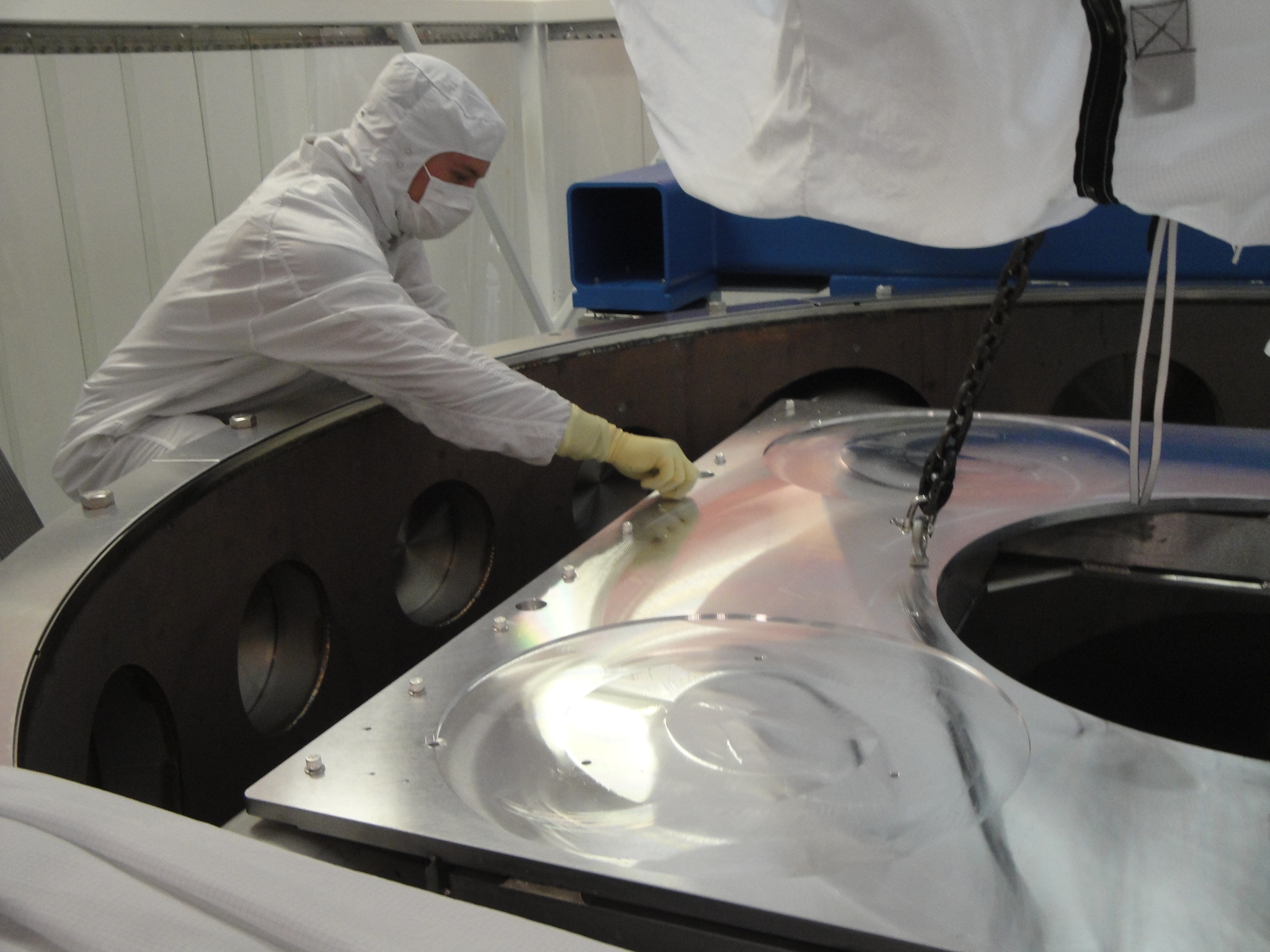
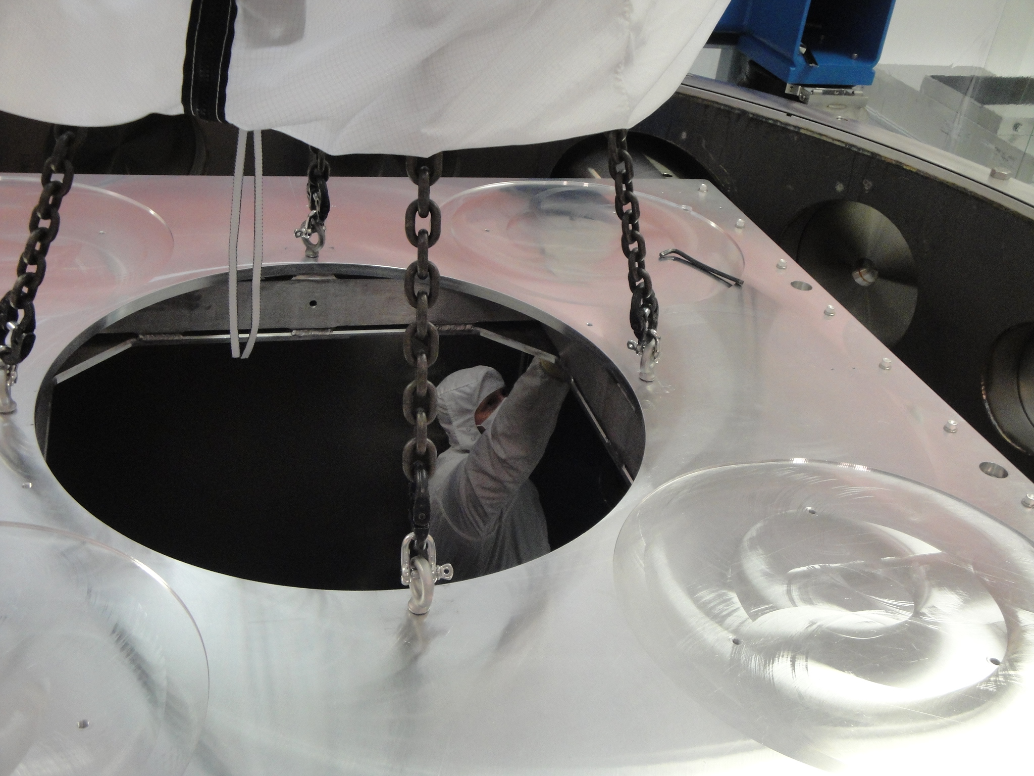
Sunday we brought all the auxiliary optics chamber-side, removed FC, inspected and cleaned as needed. Same for the corrisponding balck glass. We then installed optics and black glass in their mounts and positioned them on the HAM table (the forks use the right holes on the table, and the optics are roughly in the right position, but tno alignment whatsoever was done). The optics that we installed on the table are:
ROM RH2
AROM RH2
ROM RH9
ROM RH1
AROM RH1
ROM RH3
ROM RH4
ROM RH6
ROM RH5
ROM RH11
ROM LH2
ROM LH1
AROM RH4
We did not install ROM RH12 (pick-off mirror for the parking beam) as we need to locate the special post. We also run into a problem with AROM RH4: we accidentally installed it in the post with the wrong orientation, and when we tried to remove it we stripped the peek screw head. We solved the problem by moving the picomotors to a new unactuated mount (need to check with Keita that this is fine) and installing a spare in it. The original optic is still stuck in the mount and we'll have to find a way rescueing it...

Ooops, by reverting to an earlier h1iopsusb123 model we undid my change covered by the original WP 3582 which took the Beam Splitter out of the trip logic. So after about 90 seconds the DACKILL was getting triggered due to the missing BS OSEM signals.
We shutdown h1susitmy, rebuilt and reinstalled h1iopsusb123 sans BS trigger, tested by waiting a couple of minutes with no trip, then restarted h1susitmy (manually safe.snapped to be extra safe).
We think now we have finished this change. We kept the SEI DACKILL triggers (DACs killed) because team ISI were shaking the stack manually out on BSC1.