I am still running TFs on HAM3 MC2 today unless someone states a need for this suspesnion system. Email me if so.
Luke, Cheryl, Rodica
This morning I checked the forward rotation after the heat sink connection last night, and reoptimized slightly by adjusting the position of the single TGG holder inside the magnet. Once re-optimized, the rotation stayed within 0.2 deg from optimim (value determined by measurement uncertainties). This was verifed for powers between 27 mW and 470 mW.
I also looked for ghost beams from the 10 surfaces of the optics assembled in the Faraday so far. Four strong AR beams seem to come from TGG and QR, two being just slightly weaker probably from QR. These rest on the periscope mount and clip on the barrel of the bottom mirror and will need to be properly routed and dumped. Also strong AR from CWP2 - one beam rests on the magnet case, another on DKDP mount. Since we don't have yet the SiC hard apertures to catch all these beams, we need to make sure they are properly routed to dumps before increasing the power. Will continue the hunting tomorrow.
Cheryl and I tested the HWP and DKDP retaining rings for smooth rotation turning them back and forth under IPA flow and wiping the metal dust away every time. Once deemed acceptable we mounted the HWP. Upon initial inspection, the two 3 mm thick DKDP crystals show an elevated density of central 'dots' that did not blow away, one significantly heavier than the other. We applied First Contact on the worst looking of the two in an attempt to remove them. This is the last optic that needs to be added to the assembly.
Luke re-assembled the picomotor rotatable HWP mount so that it rotates freely. It needs to sit on the flow bench overnight so that the IPA can evaporate out of it. In the morning he plans to do one last test on it to make sure that it still rotates without IPA, and then we can install it to the breadboard.
[Jax, Aidan, Thomas]
We disabled the WFS feedback as these were clearly forcing us out of alignment. Instead we have the dither scripts running after every 5th cavity scan. The scans will continue to run all night. The ring heater is due to turn off around 5AM.
I've turned on excitation B on Common Mode A to perform a cavity scan during another ring heater test tonight. It went on at 00:54:20 UTC/17:54:26 local.
After the fiber swap mentioned yesterday, it seems that the crazy big noise (blue trace) was gone (red).
From 13:47 to 13:57 local time, I turned the laser room HEPA and A/Cs off, turned down the ante room HEPA to 55%, and make up air to 75%.
During this time the lights were ON, I and Rodica were in the ante room but otherwise things were really quiet.
Also on the plot are various noise levels from the old refcav setup. The difference between red and everything else at 1Hz is the ISI isolation.
Anyway, the red trace is the best we got today. It was glitchy and once in a while we got a big glitch, but otherwise the noise level was much better than blue. Still, the noise level was varying between red and maybe brown.
It's clear that we need a serious debugging if we want to get to the root of this, and it's not a one-day job. It seems to me that we need the corner station anyway to proceed any further, and I don't think it makes sense to block other things (including the HIFO installation) for the one arm test further.
I'll likely declare that we're done with dedicated one arm test in the morning. That doesn't mean that people cannot do one arm measurements when the arm is still available in the evenings, but we won't block installation activities during the day time.
From about 16:00 to 18:00, I turned off the laser room HEPA, turned down ante room HEPA to 55% and the make up air to 75% while leaving A/Cs on. Lights were off.
During this time, Vincent was doing his SEI measurements, but the cavity was locked for some part of this, so you can look at the length data if you want.
Later Vincent will post the details of the SEI configuration, i.e. the starting GPS time of each of the configurations, so you can tell which time to look for which configuration.
Current Issues: - FMCS was down when I came in today - it's still down... - instrument air at Mid-X had a real failure that Kyle is working on Morning meeting notes: OAT: noise until 1PM is OK, then Keita needs quiet time HAM3: MC2 - will be fixed as directed after transfer functions HAM1: passive stack install is ongoing Cabling: ISC rack install ongoing IO: Faraday work continues Viewports: Test cap used to test inside glass of PSL input viewport. Outside - glass mount modified to connect inside volume to vacuum. Light pipe left off until light needed in chamber. EX: prep for cleaning and measurements cleaning may start tomorrow ISC SLED: assembly is ongoing General: ISC table is still open in LVEA, with optics exposed Shipping for Squeezer is planned Controls Solutions - here to muck with HVAC to check sensors for flow Electric - FM200 system check tomorrow Ray Pollen Construction here to fill water tanks in outbuildings tomorrow Issue from yesterday: PSL AC off, causing temperture increase in PSL laser room by 8 degC. Why did AC issue with PSL happen? We don't fully understand the systems. HVAC system was in alarm. Readings for temperatures comes through BECKOFF, which was powered off last Friday, and when powered up again, didn't read new temperatures, but just braodcast the last known state, so was giving bogus data, so we didn't get an alarm, and didn't know the AC wasn't working.
ScottL BubbaG & Hugh Again no hangups in installing this platform. We positioned the final layer of Springs, centered up the 0.275" (D972716-3) Alum Shim and the Viton Pad D972716, & installed the centering pins. So ready to go--see photo below. Then the Optical Table was lifted in, tweaked into position over the pins, and, tellingly without any pushing/pulling of the four independent Mass stacks, lowered the Table over the pins and landed. The pins are replaced with Safety Screws, again like yesterday, without the Custom Thick Washer and suddenly it was lunch time. My camera battery died so I didn't get any further photos but we need to payload up and I'll get more pics then.
Yesterday, the H2 SUS ITMY, ETMY, & FMY user models were re-compiled and installed on the "h2susb478", "h2susb6", and "h2susb78" FrontEnds. The custom models recompiled were "h2susitmy.mdl", "h2susetmy.mdl", & "h2susfmy.mdl". Note: The TMSY custom model "h2sustmsy.mdl" was NOT recompiled or installed. However, the changes to the common library part would affect this custom model. The modifications to the user Simulink models were at the M0 level where a common part "SIXOSEM_F_STAGE_MASTER.mdl" is used by the aforementioned custom models within another common library part, "QUAD_MASTER.mdl". For "h2susitmy.mdl", this part is at the 'h2susitmy/ITMY/' level and is given the name "M0". Within this sub-block, the changes were made inside the "OFFSET" block (snapshot attached). Within this "OFFSET" block, there previously existed an "EpicsInput" block that simply was an input for the DC Alignment Offsets for Pitch and Yaw on M0. This input block was replaced by an "IIR Filter Module" such that the ability to ramp the gain is easily accessible via the MEDMs. The previous channels for the DC Offset were labelled: "H2:SUS-$(OPTIC)_M0_OFFSET_P" "H2:SUS-$(OPTIC)_M0_OFFSET_Y" As of now, this same offset may be used via the filter module channels: "H2:SUS-$(OPTIC)_M0_OFFSET_P_OFFSET" "H2:SUS-$(OPTIC)_M0_OFFSET_Y_OFFSET" The latest OFFSET values were used for these new channels (from an auto-burt snapshot saved just before the changes): H2:SUS-ITMY_M0_OFFSET_P 1 5.773156262190410e+03 H2:SUS-ITMY_M0_OFFSET_Y 1 7.655051822649471e+02 H2:SUS-ETMY_M0_OFFSET_P 1 -3.026901455243990e+03 H2:SUS-ETMY_M0_OFFSET_Y 1 5.405575230252840e+03 ------------------------------------------------------------------ As for changes to the MEDM screens, links to the RCG-generated filter module MEDMs were created inside the "SUS_CUST_QUAD_M0_ALIGNOFFSET.adl" file located locally in the directory: '/opt/rtcds/userapps/trunk/sus/common/medm/quad/' All changes to user models and MEDM files were committed to the "cds_user_apps" SVN repository.
After morning meeting, the Apollo crew (Randy, Mark L., Chris) and I went to X-end to begin serious work. We spent the first hour or so moving cleanrooms into usable position while still accommodating the dome on the clean half of the floor. We moved the bang board to a more central location for cleanroom, vacuum, air handler, and computer use. Randy and I bunnied-up to do contamination inspection. We found the usual mess : fibers of various sizes at all the flange joints, a human hair in a viewport nozzle, particulate adhering to the gate valve, etc. I'm attaching one picture just because. Next, Mark L. came into the chamber so that he and Randy could do the micrometer measurements requested by Lisa Austin. Last time Lisa was here, she noticed that there is a port in exactly the area where the cryopump baffle frame is supposed to be installed. After lunch, the crew headed back down to work on removing viewports, illuminator, camera, etc and to document the condition of the chamber. They'll also start the wrapping of the the support tubes.
Mark B. and Jeff B. Took TFs on MC1 from around 10:00. Andres was working nearby and other noisy stuff was happening but DQ not too bad.
H2:SUS-ETMY_M0_OFFSET_P etc. were changed to H2:SUS-ETMY_M0_OFFSET_P_OFFSET etc. yesterday, apparently, and ISC screen for TM offsets are now white.
From OFFSET_P to OFFSET_P_OFFSET, and OFFSET_Y to OFFSET_Y_OFFSET. Sounds as if somebody decided that we needed to put a standard cds filter module just for the offset. I don't know why, but I can believe that there's some reason. Anyway , please talk to integration testers before making such a change next time.
This change was necessary in order to allow the ramping of the gain for the very large DC offsets. Otherwise, instantaneously engaging these offsets trips the watchdogs.
The latest offsets for ITMY, ETMY, and TMSY are listed below: H2:SUS-ITMY_M0_OFFSET_P 1 5.773156262190410e+03 H2:SUS-ITMY_M0_OFFSET_Y 1 7.655051822649471e+02 H2:SUS-ETMY_M0_OFFSET_P 1 -3.026901455243990e+03 H2:SUS-ETMY_M0_OFFSET_Y 1 5.405575230252840e+03 H2:SUS-TMSY_M1_OFFSET_P 1 -7.363600000000000e+04 H2:SUS-TMSY_M1_OFFSET_Y 1 1.919600000000000e+04 These values were taken from an hourly ".snap" file taken from the directory '/ligo/cds/lho/h2/burt/2012/09/11/09:00/'.
Snapshots are not trends. Now we need to use NDS2 client for trending data from the past, which is OK but not ideal.
Luke, Cheryl, Rodica
This morning we were planing to do measurements of the FR rotation at several input power levels, but we had to defer this until the AC issues inside PSL got solved and the temperature lowered down so that the PMC becomes stable again. Meanwhile, Cheryl and I prepared and assembled a set of posts and clamps to hold the cover over the HAM Aux-es.
The retaining rings for the FI half waveplate and DKDP came out of clean and bake in the afternoon and tomorrow we will assemble these two optics in their final mounts.
We also assembled the heat sinks for the TGG crystals and the DKDP holder and mount. Luke has been assembling the pico-motor half waveplate mount. I removed the alignment input iris as it was not useful anymore and mounted a power meter to measure the FI incident power.
At some stage in the morning, I, Rodica and Cheryl thought that Laser room was hot. We checked the Beckhoff temperature monitors which looked fine, but it was so hot that we convinced ourselves that the monitors are bogus (later it turned out that Beckhoff monitors that are reporting temperatures were all frozen).
The touch panel interface from AirCare Automation was reporting that the A/Cs were both running, but they were clearly not running. Toggling running/stop from the touch panel didn't change the situation, it would say that A/Cs were running but they were not.
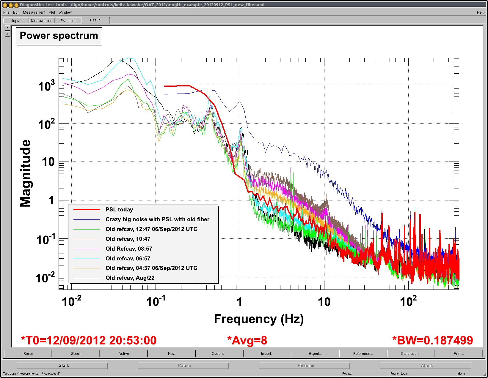
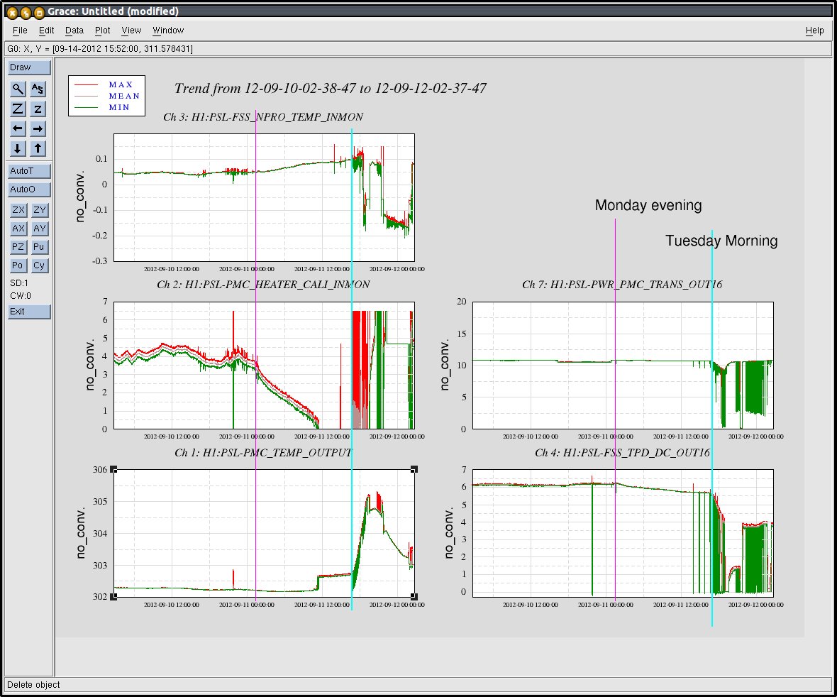
While we were trying various things, the temperature was running up quickly and the PMC started dropping lock and relocking repeatedly with a few minutes' interval because the PMC temperature servo couldn't keep up.
After a while I noticed that there are good old hardware A/C control panels from Mitsubishi in the laser room, the sensors of these panels were reporting 28 degree C instead of 20, and an error message was on the display. I switched it off and on, and after a while we felt that the temperature was coming down.
The room temperature came back to normal after a few hours, but some things (e.g. PMC) is very slow to respond, and it's still going back to where it used to. Because of this, PMC servo is dropping lock once per 10 minutes or so as of now.
I disabled the temperature servo of PMC and leave it like that for tonight.
===
I wanted to see when exactly the room temperature started rising, but I couldn't because the Beckhoff monitors were all frozen from last Friday. But anyway it should have been me because I'm the only person who touched A/C.
===
One thing though, I was told to turn A/C on and off from AirCare touch panel, but Livingston manual says this is done from Mitsubishi control panel. If this should NOT be done from the touchpanel, fine, but the touchpanel should not pretend as if it can control and monitor the status of A/Cs.
It appears that the problem with the Beckhoff for the H1 PSL environment channels was that one of the chassis was turned off (H1 Corner 2 I think). I don't know when or why this happened.
I looked at some monitors that are sort of related to PSL room temperature and found that the most likely failure point was NOT when I turned everything off (except the make up air) and then back on with some reduced HEPA setting in the evening on Monday, but it was when I turned everything back on with full speed in the morning.
For record, last night I temporarily turned off HEPA and A/Cs, and reduced the make up air to 30%, for a short while.
In the same evening I turned A/C back on, and left PSL laser room HEPA off, set PSL ante room HEPA to 55% level, and Make up air to 75%.
The time this happened is shown as a pink line in the attached. As you can see, after this, because of reduced HEPA and make up air, the temperature very slowly dropped but nothing drastic happened. At some point the temperature servo for PMC bottomed out (see Ch1 and Ch2) but the PMC was still locked (Ch7). At this point A/Cs were most likely running fine.
This morning at about 10AM (Cyan line), before anybody went into the PSL room I made sure that everything was back to 100%. I set both of HEPAs to "100" more than once, as I thought the touch panel was displaying 100% even though it should be displaying 55% when I first saw the setting. I also toggled A/Cs to make sure that the touch panel display responds to my request to change A/C status, and made sure to go back again so that it was reporting "running" for both A/Cs.
Apparently the system didn't like it, PMC temperature started going up rapidly, PMC dropped lock, and the refcav transmission dropped drastically (Ch.4) probably because of the alignment drift caused by the temperature change.
The change in temperature was noticed by us, and at about noon A/Cs were turned on again via Mitsubishi control panel, so we were A/C-less for two hours.
It seems like the the alignment to the refcav never came back.
Today I pulled the ETM ring heater driver to investigate why its response to current was so different from the ITM ring heater driver. I found that resistor R44, which controls the gain of the input, was left void on the ETM. The circuit designs had been updated to include a 49.9k resistor, raising the gain by a factor of about 2. I added the 49.9k resistor, returned the ETM ring heater driver to the field, and recalibrated the driver. The calibration was performed by measuring the voltage over a 0.5 ohm resistor on the ring heater driver board (test points TP1 and TP2). The supplied current was increased from 0 to 425 "mA" of DC offset in steps of 25 "mA".
The driver's calibration is much closer to the ITM calibration, and is more consistent with using milliamps for the DC offset on the medm screen. Previously, it was calibrated at 0.0498 mA/ADC count. The updated calibration is 0.02396 mA/ADC count. The attached trace shows the data using the old calibration on the same axes as the data using the new calibration.
I edited the plot to make the axis labeling more transparent. The x-axis is the output on the channel H2:TCS-ETMY_RING_HTR_SEG2_I_MON_OUTPUT (what the MEDM screen thinks it's sending to the ring heater), the y-axis is the current calculated from the voltage measured over the sense resistor R49 on the driver.
Again, the board was modified to bring its gain in line with that of the ITM driver. The initial calibration was done for the unmodified board. The modified calibration is the correct calibration for the modified ETM driver.