Displaying reports 85041-85060 of 88665.Go to page Start 4249 4250 4251 4252 4253 4254 4255 4256 4257 End
Reports until 18:16, Sunday 05 August 2012
H1 AOS
robert.schofield@LIGO.ORG - posted 18:16, Sunday 05 August 2012 - last comment - 18:29, Sunday 05 August 2012(3724)
Arm relocked after SUS, ISI, HPI trip

With phone help from Bram, I reset  SUS, ISI and HPI,  which had tripped in the middle of the night, and relocked the arm. Low power though.

Comments related to this report
bram.slagmolen@LIGO.ORG - 18:29, Sunday 05 August 2012 (3725)

That is on BSC6.

I treid to use the new tdsdither scripts to improve the alignment, but it can't connect to h2nds0. Got the error 

controls@opsws4:scripts 0$ ./tdsdither 2.3 50 5 0 300 H2:SUS-ETMY_M0_TEST_Y_EXC H2:ISC-ALS_EY_REFL_PWR_MON_OUT H2:SUS-ETMY_M0_OFFSET_Y 10 5

		== tdsdither output format ==
(coherence magnitude phase signal time) Step dx to x

ERROR: LDAQ - Unable to connect to NDS h2nds0
Warning: tdsDemod is having trouble.  Retrying...ERROR: LDAQ - Unable to connect to NDS h2nds0
^XWarning: tdsDemod is having trouble.  Retrying...ERROR: LDAQ - Unable to connect to NDS h2nds0

I tried to do
			controls@opsws4:scripts 0$ NDSSERVER=h2nds1:8088
to force to look at nds1 without luck. Seems there is some hardcoded server address.
 
also ezcaswtich doesn't seem to work either.
 
Unfortunately will leave the cavity with a less than optimal alignment.
LHO General
patrick.thomas@LIGO.ORG - posted 19:43, Friday 03 August 2012 (3722)
plots of dust counts
Attached are plots of dust counts > .5 microns in particles per cubic foot.
Non-image files attached to this report
LHO General
patrick.thomas@LIGO.ORG - posted 17:57, Friday 03 August 2012 (3721)
dust monitor at end X
I have placed a dust monitor in the clean room at end X. It is set to location 1.
H2 ISC
bram.slagmolen@LIGO.ORG - posted 17:15, Friday 03 August 2012 (3719)
OAT locked for the weekend

Reset the watchs dogs for ITM SUS, ISI and HEPI (needed to zero the ITM dc alignemtents).

I did a quick dither alignment of the TM to the laser beam.

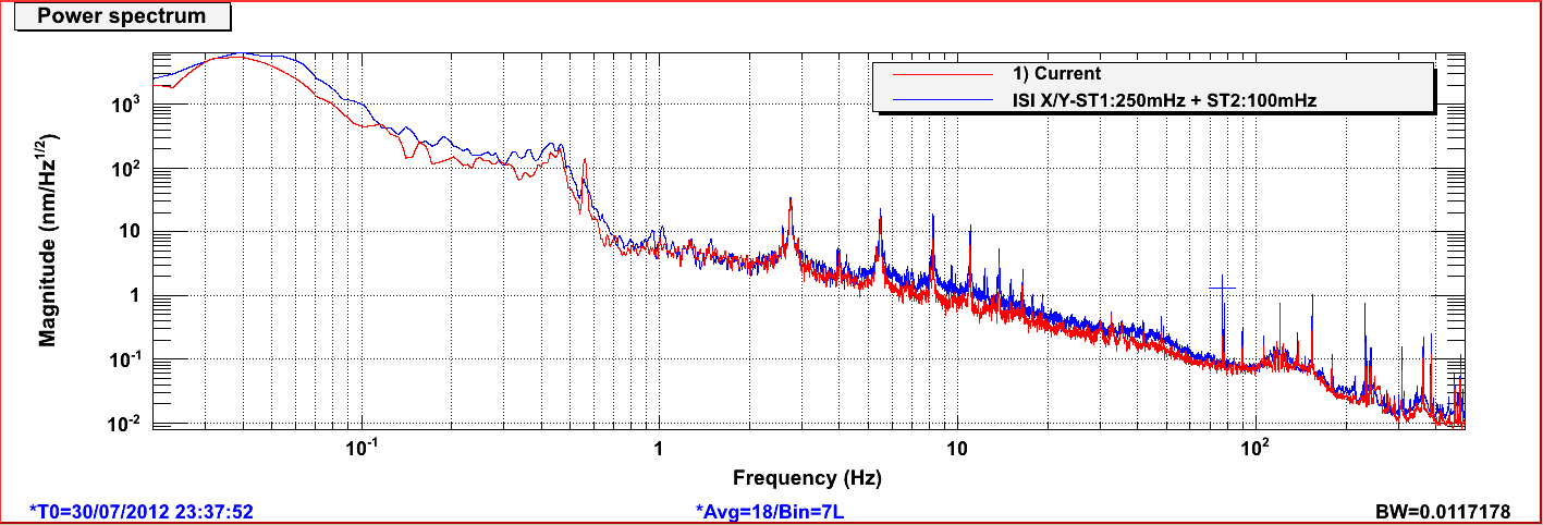
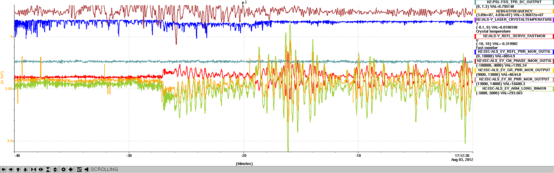
I engaged the ISI isolation on both ITM and ETM (I think they don't have the boost on), and enabled the offload to the ETM HEPI.

attached are a spectrum and a striptool.

All is running smoothly.

Images attached to this report
H2 AOS
bram.slagmolen@LIGO.ORG - posted 16:52, Friday 03 August 2012 - last comment - 17:23, Friday 03 August 2012(3718)
FMY USER DACKILL

In the H2 FMY suspension the USER DACKILL has white screens. I am not even sure if the damping feedback is going out to the suspension or not.

I would not be able to reset this if it had tripped. Would be nice if this can be fixed.

Comments related to this report
jeffrey.garcia@LIGO.ORG - 17:23, Friday 03 August 2012 (3720)
The white medm is only indicative of the fact that the medm is a little out of date and is looking at another channel that probably doesn't exist. FMY is currently being damped, however. There are still values being sent out from the IOP DAC medm, so all indications are that the actuation is reaching FMY.  
H2 ISC
bram.slagmolen@LIGO.ORG - posted 16:48, Friday 03 August 2012 (3717)
OAT RefCav

Removed the 90/10 beam splitter in front of the RF LSC diode, and replaced it with a 50/50 beam splitter. Adjusted the gain to set the UGF to ~300 kHz. I tried to insert a ND filter to see if the 2.74 Hz peak disappears, but don't have a conclusive result yet.

LHO VE
kyle.ryan@LIGO.ORG - posted 16:45, Friday 03 August 2012 (3716)
Leaks on Vertex output MC tube flanges
Progress on the leak testing of the Vertex has been hampered due to the prevalence of "very" loose bolts on 80% of the flanges on the GNB provided MC spools.  After finding that 12 of the first 15 flanges tested were leaking badly I ceased spraying any additional helium and, instead, torqued the bolts on the flanges which were leaking.  This was very time consuming and was not "on the schedule" but did manage to demonstrate that the majority of leaking flanges could be made leak tight by doing this. 

I will propose that all of the GNB joints (leaking and not yet leaking) be torqued on Monday (Apollo help?) before continuing on with the helium leak testing. 
LHO General
cheryl.vorvick@LIGO.ORG - posted 16:25, Friday 03 August 2012 (3715)
Ops Day Summary
Aug. 3 OPS:

Start of the day: 
ISI tripped on ETMY - HEPI tripped on ITMY - Vincent looking into it, Bram emailed

Work going on:
craning arm to install on HAM3
Filiberto to EY to pull network cable
Karen to LVEA to clean
Patrick working in the NYN room
Patrick to EX to install dust monitor
Eric to HAM2 to install hardware on actuators
Kyle to EY - retrieving equipment from VEA
Alex to EY - inventory in TMS lab
Michael R. to EY TMS lab to verify tagged out lasers
Doug to HAM3 optics table to measure some threaded hole diameters
Karen and Chris to EY to clean
HAM3 has an ARM attached to it
H1 SUS
jeffrey.bartlett@LIGO.ORG - posted 15:15, Friday 03 August 2012 (3714)
H1-MC3 Phase 1b Testing
[Jeff Bartlett and Andres Ramirez]

After replacing a broken magnet on the H1-MC3 intermediate mass, we ran Phase 1b transfer function. The results showed a rubbing issue at the side and left BOSEMs on the M1 Level, (2012-07-30_2100_X1SUSMC3_M1_ALL_TFs). While looking for something rubbing on the upper mass (which we did not find), discovered the T3 BOSEM showed no voltage, which was traced back to a loose connection at the D25 end of the cable. After reseating the cable, the SpeedDials values still did not look right. We reran the Open Light script for T3. The Open Light voltages were OK; the Offset and Gain values in MEDM were not correct. We reran the Open Light script for all the BOSEMs and adjusted the MEDM offsets and gains as necessary. 

We reran the transfer functions this morning (2012-08-03_0730_X1SUSMC3_M1_ALL_TFs), the results look much better. Requesting final approval for metal build of H1-MC3.    
Non-image files attached to this report
H2 ISC
bram.slagmolen@LIGO.ORG - posted 22:49, Thursday 02 August 2012 (3711)
ALS-Y-PLL

[Elli and Bram]

After the OAT RefCav work, we relocked the PLL in EY. We had to tune the laser crystal temperature up to 42.27 degC (from 42.08 degC). We also teaked the waveplate, setting the beatnote power to -31dB.

H2 ISC
bram.slagmolen@LIGO.ORG - posted 22:40, Thursday 02 August 2012 (3708)
OAT RefCav

I had a look at the refernce cavity today to see where we losing our gain. Initially I tweaked the alignment increasing it by approximately 10%, the 01-mode is now much dimmer on the monitor (I didn't do a scanning alignment, and tried to kept the cavity locked).

Also, I rotated the QWP just infront of the cavity to maximise the power on the RF LSC diode. In the beam just after the PBS, which taps the beam for the RF LSC diode, is a ~90/10 beam splitter (unlabelled), directing 90% of the beam to a CCD camera! Due to a lack of looking for a smaller splitting ratio beam splitter I left it inplace, so we now geting ~4 mW onto the RF LSC diode (of the 34.4 mW available in the return beam).

I dropped lock, so I could measure the power. Into the cavity is 46 mW, reflected is (out of the PBS) 34 mW. I measured the power incident on the transmitted diode but forgot to measure the total power transmitted! There is 4 mW on the RF LSC diode (reading 169 mV at the DC output). Once locked the power drops to 40 mV out of the DC output.

The UGF is 287 kHz, with the folowing Interface Settings

Coaers Fine Common Fast Offset
340 512 800 680 294

It runs with Common at 850 and Fast at 700 (UGF 315 kHz), but it becomes more sensitive to bumping and floor motion and starts to oscillate.

You can recover from the oscillation by reducing the Common gain to below 160, and bring it back up.

The relock of the RefCav is at a slightly different mode, asI tweaked the coarse tuning down wards to find the 00-mode. There is 210 micro Watts on the transmitted diode, reading ~828 mV (it has a gain setting of 20 dB).

LHO General
patrick.thomas@LIGO.ORG - posted 20:05, Thursday 02 August 2012 (3710)
plots of dust counts
Attached are plots of dust counts > .5 microns in particles per cubic foot. The dust monitor at location 8 in the LVEA (H0:PEM-LVEA_DST8_5) was put in the assembly prep area near HAM2 and HAM3.
Non-image files attached to this report
H2 ISC
bram.slagmolen@LIGO.ORG - posted 17:53, Thursday 02 August 2012 (3709)
Arm Locking

Vincent finished installing the HEPI system. Because the ISC signals are now added into the HEPI feedback just after the compensation filters, the gain and sign have changed.

Now we have a gain of -2 (from +0.2). Also the units are not in nm anymore .... not a drama but makes thinking about limits a bit harder ...

I engaged the ISI isolation on ITM, but the ETM kept tripping so I left it in damping only (didn't further investigate).

Left the cavity locked for the night.

LHO VE
kyle.ryan@LIGO.ORG - posted 16:44, Thursday 02 August 2012 (3707)
More leak testing at Vertex output MC
Kyle 

With the leak detector configuration as left yesterday, i.e. backing the Vertex MTP (100% of the turbo exhaust) the helium background had decreased from 1.3 x 10⁻⁸ torr*L/sec (as left yesterday) to 6.2 x 10⁻⁹ torr*L/sec today -> I vented the HAM5 and HAM6 annulus volume and decoupled the HAM5 aux. pump components leaving the pump port connection open to the room.  Then I let the HAM6 aux. cart diaphram backing pump pump air through the annulus, i.e. room air enters HAM5 pump port and routes through annulus volume and exits HAM6 pump port.  This was another attempt to expedite removal of any helium permeated in the annulus O-rings -> No help, too slow.  Next I calibrated our 2nd leak detector and swapped it in place of the initial leak detector -> No change.  It measured and behaved within 10% of the first.  This was done to rule out any instrument-specific inability the initial leak detector might have had in resolving helium ions from non-helium ions in the spec. tube (as the leak detector inlet pressure is relatively "high" baking the MTP).  This concludes my attempt to get the helium background to the nominal <2 x 10⁻⁹ torr*L/sec value.  

Moving on, I reconnected the initial leak detector and began testing CF joints on the output MC tube with a background of 6.2 x 10⁻⁹ torr*L/sec.  Two of the first three flanges I tested were 10-6 range leakers!! Ouch!!  Will have to continue tomorrow after this pumps away.  
LHO General
corey.gray@LIGO.ORG - posted 16:10, Thursday 02 August 2012 (3647)
Day Shift Ops Summary

Day's Activities:

Since there was not OAT activities during the day, this allowed for noisy activities in the LVEA/EY.

H2 SEI
vincent.lhuillier@LIGO.ORG - posted 15:44, Thursday 02 August 2012 (3706)
HEPI model modifications - BSC6 - BSC8

This morning, the HEPI master model was updated, corrected and committed. The two HEPI models (BSC6 and BSC8) were recompiled, re-installed, restarted and restored. The safe burt snapshots were updated. Bram was able to lock the cavity with the new configuration.
Note that the Yaw offset is now introduced in the DC_BIAS and the ISCMON filter output signals are not going through the isolation filters.
Now, ISC signals can be read by the HEPI models using the reflective memory.

H2 AOS
thomas.vo@LIGO.ORG - posted 17:15, Thursday 26 July 2012 - last comment - 16:26, Wednesday 08 August 2012(3614)
H2 ITMY/ETMY Optical Lever Calibration
Jeff K. , Thomas V.

Below are the calibration parameters for the H2 ITMY Optical Lever:
        Slope          Y-intercept
Pitch [ 580.41229822  -11.51774017]
Yaw  [ 689.70532274  -13.3345144 ]


And here are the calibration parameters for the H2 ETMY Optical Lever:
         Slope           Y-intercept 
Pitch [ 1666.80728788   -33.14694715]
Yaw  [ 1727.67131855     23.41350328]

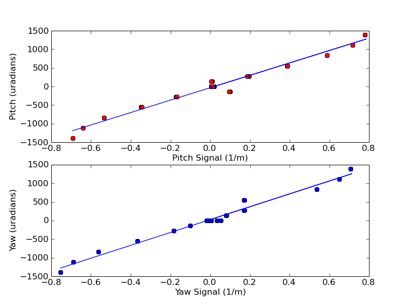
Both sets of calibrations were attained via the same process of moving the QPD along a translation stage and measuring the output signal.  All four sets of slopes are in units of radian*meters.
Images attached to this report
Comments related to this report
thomas.vo@LIGO.ORG - 14:40, Friday 03 August 2012 (3713)
Jeff K. Thomas V.

We have found a non-linear relationship between the way the translation stage moves and the way we were reading out the measurements.  We need to double check the calculations as well as the methodology on retrieving data.  This latter is difficult because even though there is a micrometer on the translation stage it is covered by the laser enclosures, which if we take off, it will introduce ambient light onto the QPD.  We are currently investigating solutions.
jeffrey.kissel@LIGO.ORG - 11:59, Monday 06 August 2012 (3736)
T. Vo, J. Kissel

Pulling out a spare translation stage and measuring the displacement response (in [mm]) to controller demands (in [ct]), we found the following attached relation. Immediately turned off by the non-linearity seen, from our experience with the controlers jolting the translation stage upon power on/off, and from Kissel's recollection of the controllers in i/eLIGO (of which these controls are the same), we've launched into a more sophisticated characterization of the controllers. Given that the non-linearity is roughly 1 [um] over the 1 [mm] range measured, we might be barking up the wrong tree and just be over-reacting, but it should be a quick round of measurements to assess it in more detail.

It should also be noted that the controller can demand from 0 to ~8600 [ct], and we've thus far only exercised it from 0 to 150, since we only need ~1 [mm] range given the size of the Oplev QPD.
Non-image files attached to this comment
jeffrey.kissel@LIGO.ORG - 13:03, Monday 06 August 2012 (3737)
T. Vo, J. Kissel

Here're the results from the more detailed characterization. It looks like, within a small range of operation the controller is indeed linear to the desired level. However, over the full range of the controller, there's certainly some non-linearities present.


Notes:
Linear UP -- commanding the stage to move from 0 (4000) up to 150 (4150), in linear 10 [ct] increments.
Linear DOWN -- commanding the stage to move from 0 (4000) up to 150 (4150), in linear 10 [ct] increments.
Random -- going to each data point in a random order

Each of these should yield the same answer if it's a truly linear system.
Non-image files attached to this comment
thomas.vo@LIGO.ORG - 16:26, Wednesday 08 August 2012 (3758)
Jeff Kissel Thomas Vo

After reviewing the linearity of the translation stage as shown in ALOG 3737, we found that the non-linear regime of the translation stage resides near the end of the rails of the stage but the approximate middle yielded linear results.  We're confident that the increments that we used to translate the stage during calibration for both test masses were small enough and far enough away from the edges so that the non-linearity would have a small affect on our results, this will require further testing to truly be valid (in progress).  That being said, after correcting some errors in the calculations and double checking our numbers, we used the original data to apply to the calibration.  

A noteworthy point: Jeff Kissel used the edrawing from the solidworks model in,

LHO Corner Station: D0901469-v5 
LHO EY Station: D0901467-v6 

to find a more accurate number for the lever arms than previously used, ITMY = 56.4m and ETMY = 6.6m, as opposed to 70m and 6m respectively.  This was taken into account for our last calculation.

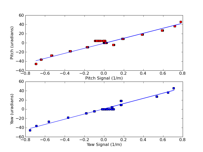
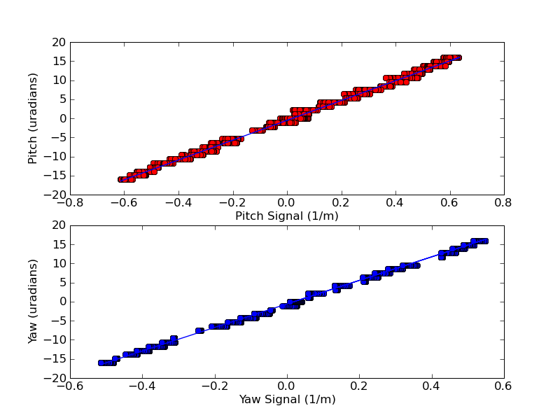
Onto the good stuff, the values of the slopes below are in micro-radians*meters:

ITMY
        Slope         Y-Intercept
Pitch [ 25.93274501  -0.51461109]
Yaw   [ 30.81584154  -0.5957635 ]


ETMY
        Slope         Y-Intercept
Pitch [ 54.53112025  -1.01505634]
Yaw   [ 56.56393367   0.79879263]


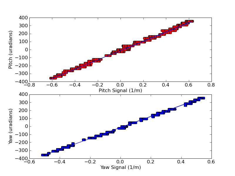
Attached are the graphs of the linear response curves, the python fitting scripts and the EXCEL spreadsheets to help visualize the underlying calibration calculations. In particular, the excel spreadsheets shows the conversion from controller units into millimeters and then into meters and micro-radians.  Hope this is the last time we'll need to repeat this post, sorry for the troubles!
Images attached to this comment
Non-image files attached to this comment
H1 SEI
hugh.radkins@LIGO.ORG - posted 13:28, Wednesday 25 July 2012 - last comment - 10:10, Friday 03 August 2012(3586)
H1 HAM3 HEPI Actutors Attached & Released--IAS says OK! Prt Duex
OK now we have all the HEPI Actuators attached & released at the correct elevation and IAS has signed off on the position.

Elevation & level is 0.1mm below nominal of -250.5mm (wrt LIGO Global) with a +-0.1mm levelness.

Attached is my field notes of the final dial indicator readings and the level survey-enjoy.

Thanks to Mitchell & Jason
Non-image files attached to this report
Comments related to this report
hugh.radkins@LIGO.ORG - 10:10, Friday 03 August 2012 (3712)
I misspeak above where I say wrt LIGO Global.  The number above, -250.5mm is the LIGO Global elevation corrected to the local leveling field.  The HAM ISI Optical Table is positioned to -252.9mm.  2.4mm is the correction to local level hence the -250.5mm; please pardon the confusion. -H
Displaying reports 85041-85060 of 88665.Go to page Start 4249 4250 4251 4252 4253 4254 4255 4256 4257 End