TITLE: 06/17 Eve Shift: 2300-0800 UTC (1600-0100 PST), all times posted in UTC
STATE of H1: Observing at 150Mpc
OUTGOING OPERATOR: Ibrahim
CURRENT ENVIRONMENT:
SEI_ENV state: CALM
Wind: 10mph Gusts, 6mph 5min avg
Primary useism: 0.02 μm/s
Secondary useism: 0.06 μm/s
QUICK SUMMARY:
Observing at 155 Mpc and have been Locked for 5.5 hours
Further testing on the revised A2L script today. On Friday Sheila added a settling time between steps that seemed to help (alog78438), and had increased the run time of the script to just under 7 minutes. Today we wanted try two things: i.) run it a few times in succession to see if we get the same results ii.) swap the furthest quad frequencies and see if we get the same results. This was only for Y and was right after we relocked and were still thermalizing.
ETMX | ETMY | ITMX | ITMY | |
Run #1 (Line Frequencies) | 31.5 Hz | 28.5 Hz | 26.5 Hz | 23.5 Hz |
Initial |
4.91 | 1.0 | 2.85 | -2.45 |
Final | 4.92 | 0.97 | 2.86 | -2.45 |
Difference | 0.01 | 0.03 | 0.01 | 0.0 |
Run #2 (Line Frequencies) | 23.5 Hz | 31.5 Hz | ||
Final | 4.93 | 1.04 | 2.83 | -2.44 |
Difference |
0.01 |
0.07 | 0.03 | 0.01 |
Run #3 (Line Frequencies) | 23.5 Hz | 31.5 Hz | ||
Final | 4.89 | 1.06 | 2.80 | -2.41 |
Difference | 0.04 | 0.02 | 0.03 | 0.03 |
Swapping the line frequencies didn't seem to change much, rather the quads that kept their frequencies changed more. This might hint that we are drifting at the frequencies that A2L should help with, so we will get different answers each time we run it. We only ran it 3 times and while we were still thermalizing, so perhaps we need to run it again after thermalized and see if we still get the same answers.
Camilla, Andrei, Naoki, Sheila
There have been many examples of times when the filter cavity length locking error signal peak to peak seems to be correlated with worse range over the last 3 months, I've attached some screenshots of examples. This was true before the May 16th change in the status of the CO2 ISS channel , 78217, and before the output arm damage that happened April 22nd.
Some of these times correspond to times when there is a whistle visible in the FC WFS signals 78263, others do not. These whistles in the FC WFS channel have been present throughout all of O4, but they do go away sometimes for several days, this last week they do not seem to have been present. Andrei has identified a candidate wandering line in the IOP channels for these WFS that was last week ~10 kHz away from the 105kHz RLF-CLF signal, today that line seems to be gone.
Last week, the filter cavity error signal peak to peak became much noisier than it was previously (screenshot), until June 15th at around 15 UTC when things returned to the previous state. Camilla identified that this started a few hours after the time of the ringdown measurement attempt, 78422, and that there haven't been any ZM1/2/3 alignment changes. During that time period, the FC error signal from around 0.7-9 Hz has higher and variable, in addition, the low frequency noise was changing and varriying the RMS as it has done before. The attached screenshot shows some of the typical low frequency variation (compare yellow to blue), a whistle in the yellow trace, and in red a time during last week's elevated noise when the low frequency was relatively quiet but there is elevated noise from 0.7-9Hz.
As part of a detchar request that is related to this, I ran the tool lasso on four different days in which their were some range drops. The days (and the linked results) are below:
Lasso normally uses the mean trends of the auxillary channels to try and correlate with the range, but I used the max trends instead as requested. The results from lasso are interesting. On the 17th, there is a correlation with H1:SUS-MC3_M3_OSEMINF_UR_OUTPUT.max and the CO2 channel H1:TCS-ITMX_CO2_ISS_CTRL2_OUT16.max. On the 21st, the range lines up pretty well with a filter cavity channel, H1:SUS-FC2_M3_NOISEMON_LR_OUT16.max. On the 27th, lasso still picks out the TCS ITMX C02 channel, but the second most correlated channel is another H1:SUS-FC2_M3_NOISEMON_LL_OUT16.max channel. There are two drops around ~4:30 and ~8:30 UTC and they seem to match up with this FC2 channel, which seems similar to what happened on the 21st. On the 30th, lasso seems to pick out a lot of ISI BLRMS channels, which is different that the other days. The top channel is H1:ISI-HAM7_BLRMS_LOG_RY_1_3.max. Overall there does seem to maybe be some relation between the CO2 channel and these filter cavity channels.
Link to Report
Andrei, Naoki
Following 78422, we did FC visibility and ringdown measurement to get the FC loss and finesse. The measured FC loss is 44+-27 ppm, which is consistent with before within the error. The measured FC finesse is 8000-11000, which is higher than expected value ~6700. We don't know why the estimated finesse is higher than before, but both results would indicate that there is no obvious excess FC loss compared to before.
After the cabling in 67409, the OPO dither lock did not work well as before. We increased the dither lock gain from -10 to -30 and the dither lock got much better. The SDF is accepted.
We needed to flip the sign of FC CMB to lock the FC green. We engaged one boost in FC CMB as before.
We turned off LP100 in FC IR trans PD. We reduced the seed power down to 0.2 mW. More than 0.2 mW seed saturated the FC IR trans PD without LP100.
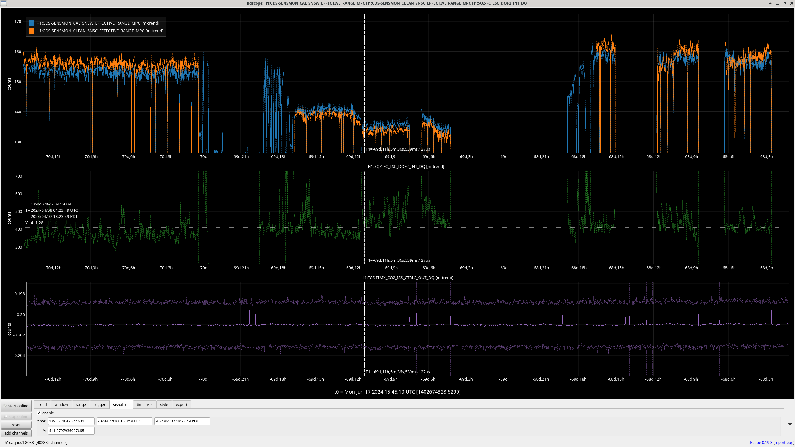
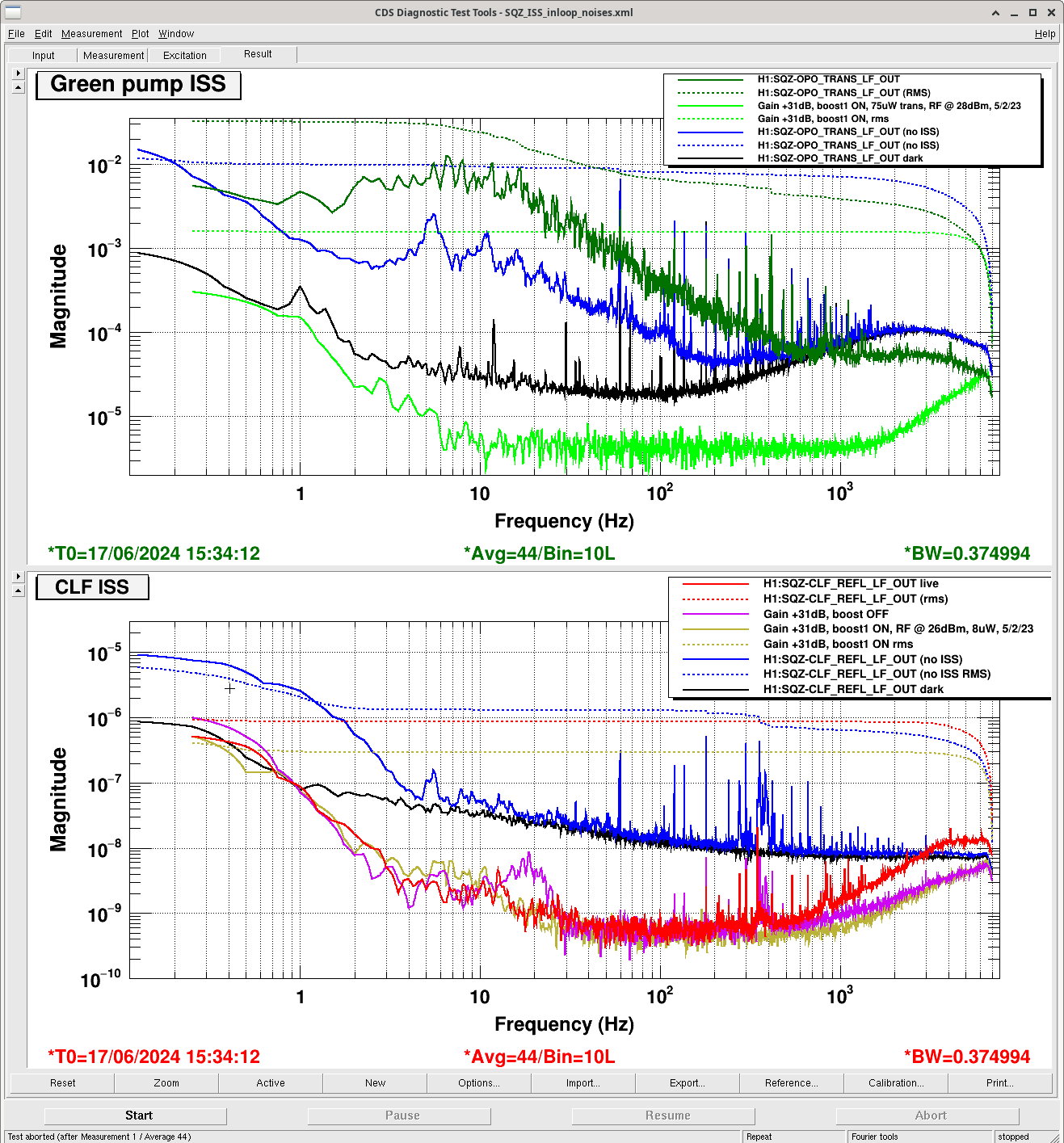
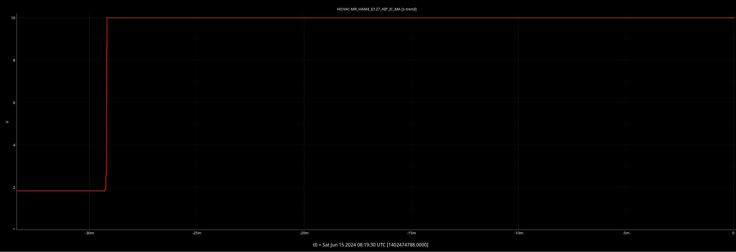
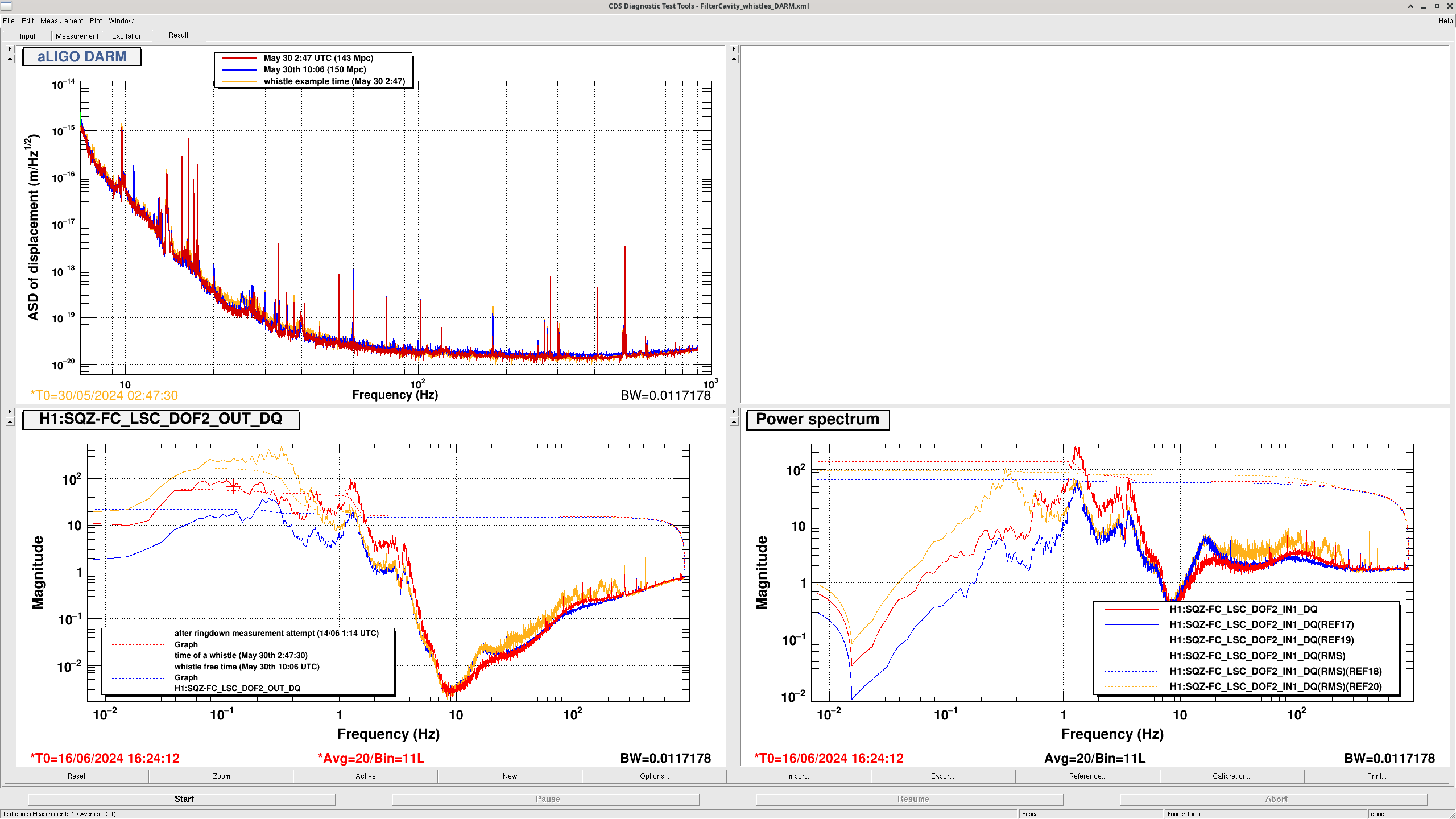
For visibility measurement, we put the seed on resonance of FC by adjusting green VCO tune and put the large offset on green VCO tune to make the seed off resonance of FC. The first attachment shows the visibility measurement.
Using the formula in TAMA paper, Andrei calculated the FC loss. The calculated FC loss is 44+-27 ppm assuming 909 ppm of FC1 transmissivity and 2% of misalignment, mode mismatch. The FC misalignment and mode mismatch are not measured recently, but they do not affect the result much.
The seed lock on FC is not very stable so the seed dither lock for FC is necessary for more precise measurement.
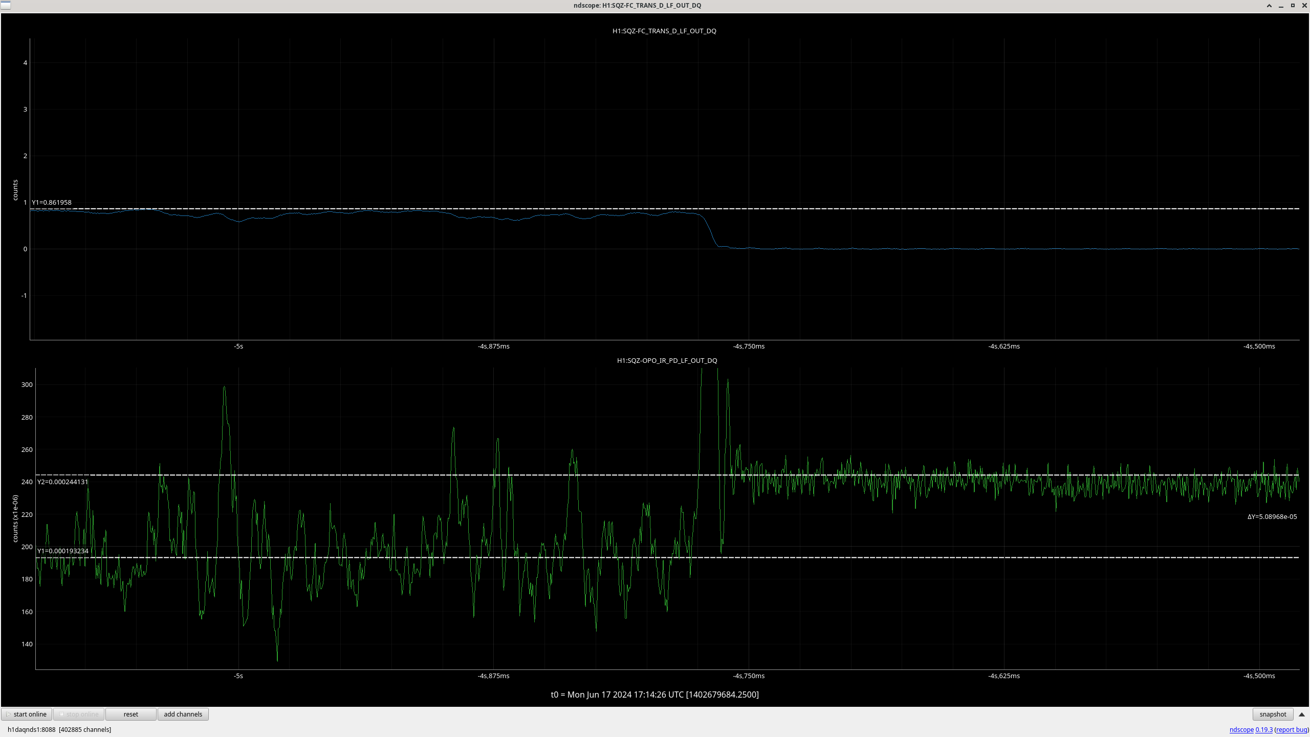
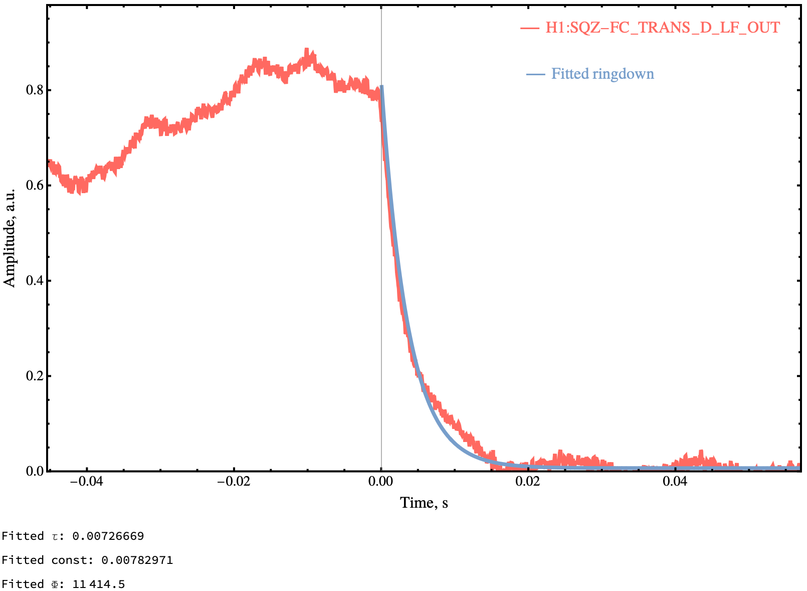
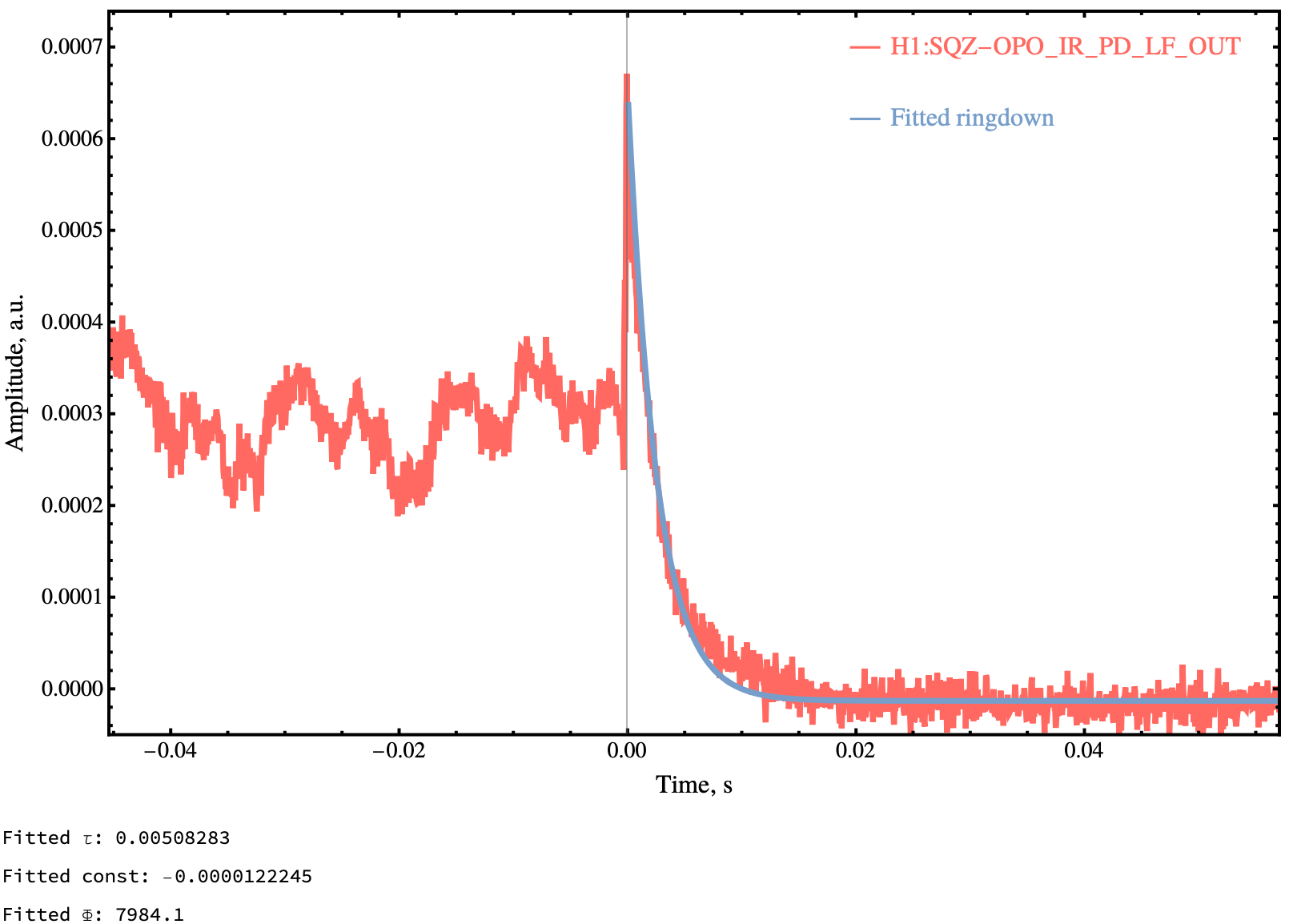
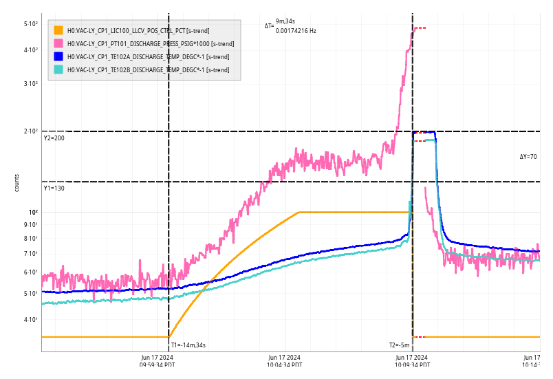
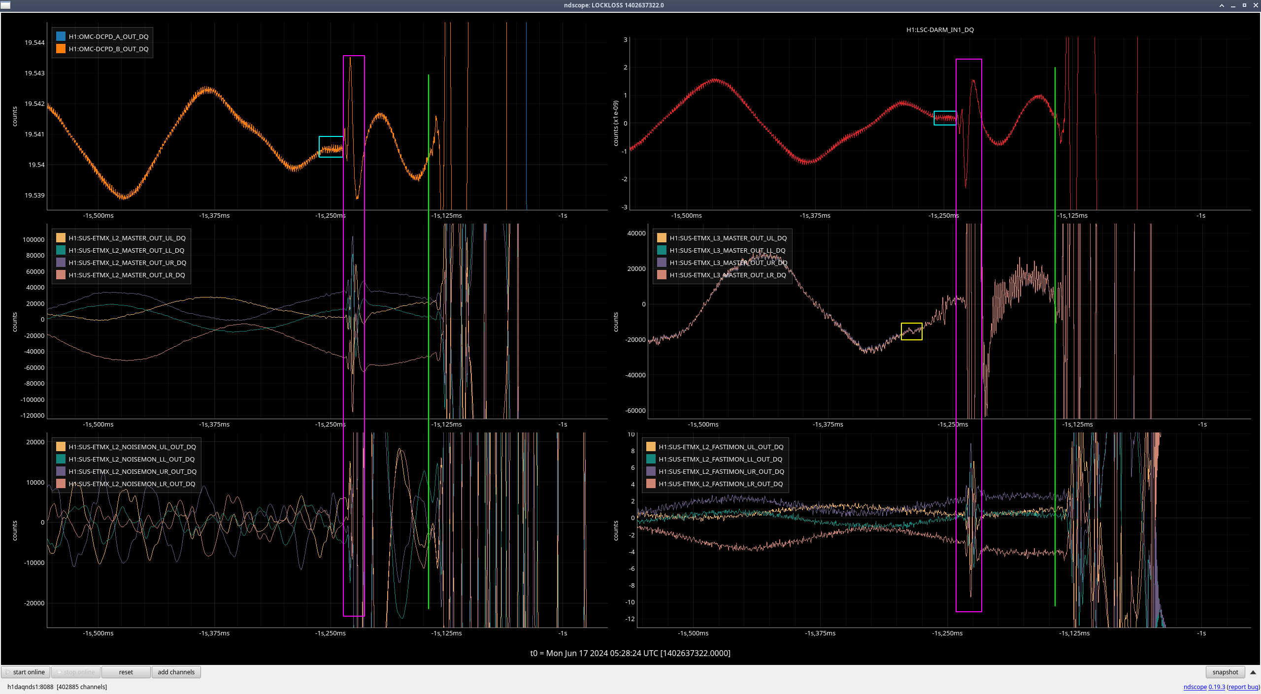
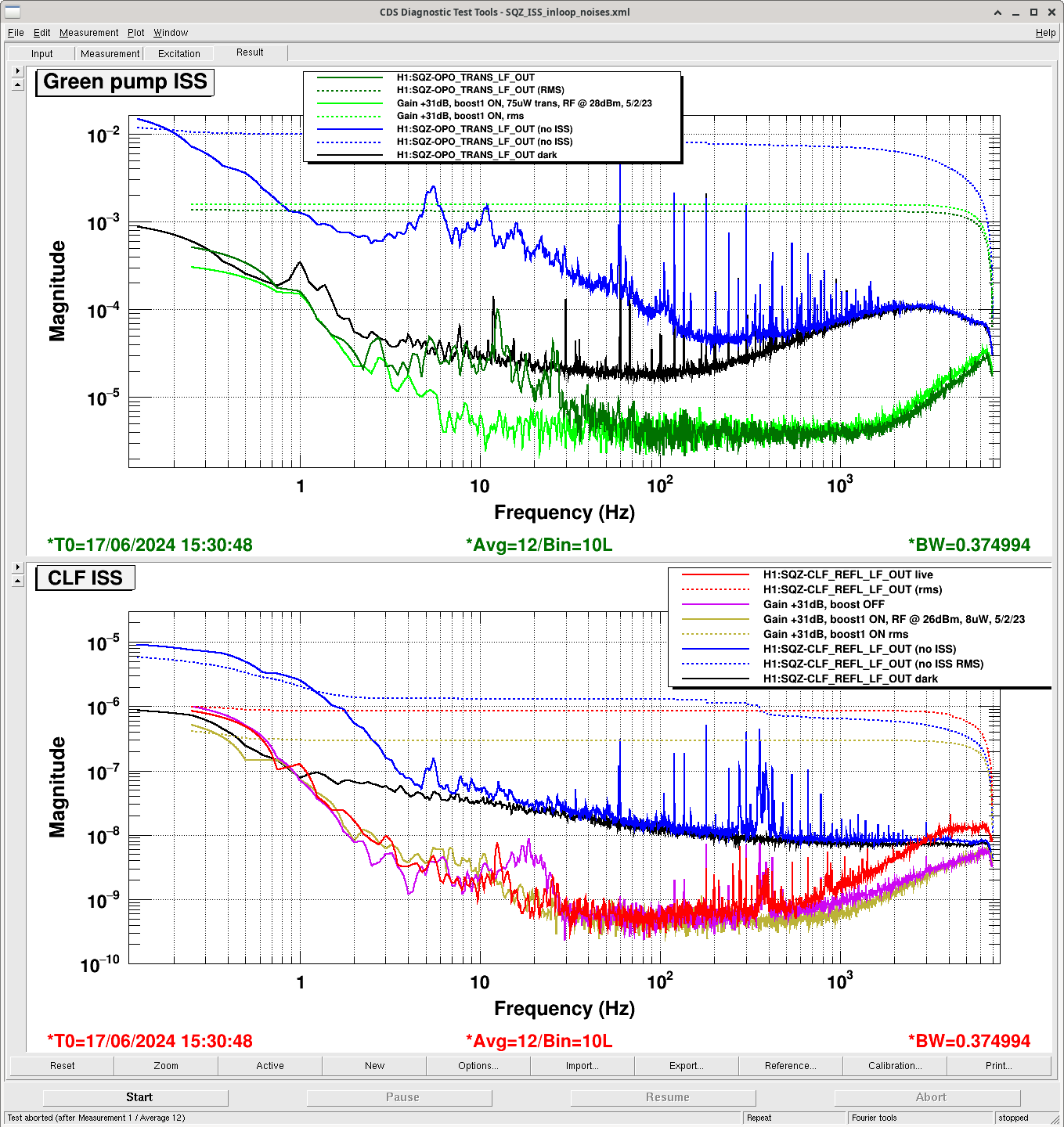
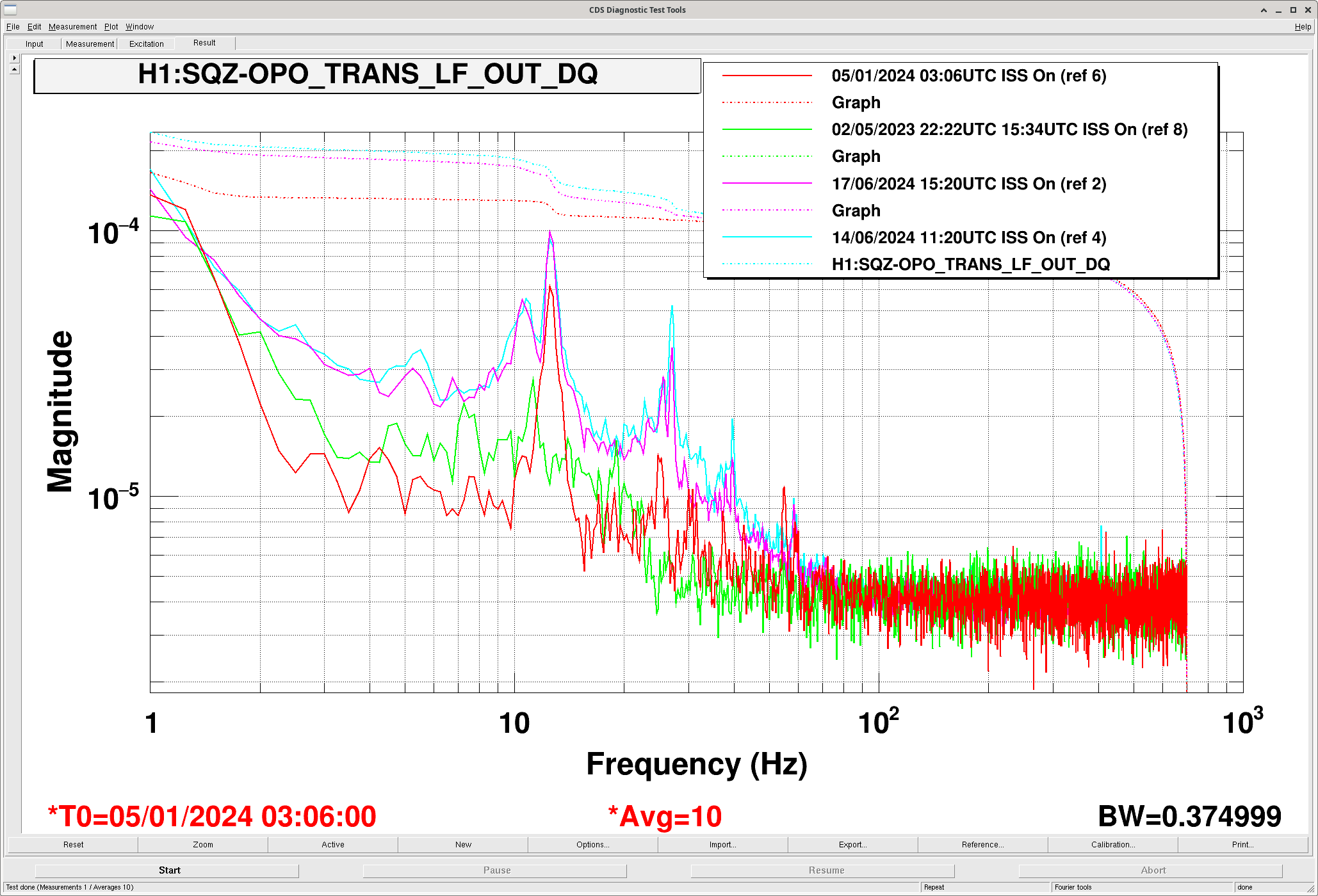
For ringdown measurement, putting the large offset on green VCO tune is not fast enough. We requested OPO guardian to DOWN. The second and third attachment show the ringdown measurement for TRANS and REFL. The measured finesse was 11000 for TRANS and 8000 for REFL, which is higher than expected value ~6700.
We've been talking about moving LSC FF back from ETMY L2 to ETMX L3 73420 as we think that it's been harder to fit the SRCL FF since using the L2 stage. Also LSC FF needs regular readjustment now. We originally moved LSC FF off EX L3 as thought that changing actuation strength may have been changing them (may have not have been the reason), but we now have a script to adjust actuation strength based on kappa_tst 78403.
If we do this, things that will be useful:
IFO is in NLN and OBSERVING as of 18:33 UTC (1 hr 46 min lock)
One unexplained potentially EQ-related lockloss occured at 15:42 UTC but we managed to relock after an initial alignment.
3 Hours Comissioning time finished on schedule (8:30AM to 11:30 AM PT) and we were back in OBSERVING by 11:33 PT
Sheila, Camilla
Sheila suggested that what happened on June 14th was that SQZ OPO temperature or angle wasn't well tuned for the green OPO power, when the OPO ISS as off, the SHG launch power dropped from 28.8mW to 24.5mW. it was just chance that SQZ was happier here. Since Saturday we've been injecting ~25.5mW 78467.
While looking at this, you can see the SQZ-OPO_TRANS_LF signal has got more noisier since the January break in the 0-60Hz region. Plot here. Maybe this is expected from the PMC install?
Mon Jun 17 10:09:34 2024 INFO: Fill completed in 9min 30secs
Gerardo confirmed a good fill via camera.
TITLE: 06/17 Day Shift: 1430-2330 UTC (0730-1630 PST), all times posted in UTC
STATE of H1: Observing at 152Mpc
OUTGOING OPERATOR: Corey
CURRENT ENVIRONMENT:
SEI_ENV state: SEISMON_ALERT
Wind: 7mph Gusts, 5mph 5min avg
Primary useism: 0.04 μm/s
Secondary useism: 0.08 μm/s
QUICK SUMMARY:
IFO is in NLN and OBSERVING since 11:45 UTC (2hr 55 min lock)
TITLE: 06/17 Eve Shift: 2300-0800 UTC (1600-0100 PST), all times posted in UTC
STATE of H1: Observing at 155Mpc
INCOMING OPERATOR: Corey
SHIFT SUMMARY: Currently Observing at 160 Mpc and have been locked for over one hour. Two locklosses during my shift, but both were easy to relock from.
LOG:
23:00UTC Detector Observing and Locked for 21 hours
23:22 Kicked out of Observing due to two cameras, ASC-CAM_PIT1_INMON and ASC-CAM_YAW1_INMON glitching or restarting
- Weren't able to turn back on fully and gave the warning messages "[channel_name] is stuck! Going back to ADS"
- Referencing alog 77499, we contacted Dave and he restarted camera 26 (BS cam)
23:43 Back into Observing
01:37 Lockloss
- During relocking, COMM wasn't able to get IR high enough
- I stalled ALS_COMM and tried adjusting the COMM offset by hand, but still wasn't working
02:21 I started an initial alignment
02:43 Initial alignment done, relocking
03:27 NOMINAL_LOW_NOISE
03:29 Started running SQZ alignment (SDF)
03:38 Observing
05:28 Lockloss
05:35 Lockloss from LOCKING_ALS, started an initial alignment
06:00 Initial alignment done, starting relocking
06:43 NOMINAL_LOW_NOISE
06:45 Observing
Lockloss @ 06/17 05:28 UTC from unknown causes. Definitely not from wind or an earthquake
06:45 Observing
Haven't figure out the cause, but this lockloss generally follows the pattern that we have seen for other 'DARM wiggle'** locklosses, but there are a couple of extra things that I noted and want to have them recorded, even if they mean nothing.
Timeline (attachment1, attachment2-zoomed, attachment3-unannotated)
Note: I am taking the lockloss as starting at 1402637320.858, since that is when we see DARM and ETMX L3 MASTER_OUT lose and fail to regain control. The times below are milliseconds before this time.
It also kind of looks like ASC-CSOFT_P_OUT and ASC-DSOFT_P_OUT get higher in frequency in the ten seconds before the lockloss(attachemnt4), which is something I had previoiusly noticed happening in the 2024/05/01 13:19 UTC lockloss (attachment5). However, that May 1st lockloss was NOT a DARM wiggle lockloss.
** DARM wiggle - when there is a glitch seen in DARM and ETMX L3 MASTER_OUT, then DARM goes back to looking normal before losing lock within the next couple hundreds of milliseconds
HAM4 annulus ion pump signal railed about 7:50 utc 06/15/2024. No immediate attention is required, per trend of PT120, an adjecent gauge, the internal pressure does not appear to be affected. HAM4 AIP will be assesed next Tuesday.
Woke up to see that the SQZ_OPO_LR Guardian had the message:
"disabled pump iss after 10 locklosses. Reset SQZ-OPO_ISS_LIMITCOUNT to clear message"
Followed 73053, but did NOT need to touch up the OPO temp (it was already at its max value); then took SQZ Manager back to FRE_DEP_SQZ, and H1 went back to OBSERVING.
Received wake-up call at 440amPDT (1140utc). Took a few minutes to wake up, then log into NoMachine. Spent some time figuring out the issue, and ultimately doing an alog search to find steps to restore SQZ (found an alog by Oli which pointed to 73053). Once SQZ relocked, automatically taken back to OBSERVING at 517am(1217utc).
Sheila, Naoki, Camilla. We've adjusted this so it should automacally relock the ISS.
IFO went out of observing from the OPO without the OPO Guardian going down as the OPO stayed locked, just turned it's ISS off. We're not sure what the issue with the ISS was, SHG power was fine as the controlmon was 3.5 which is near the middle of the range. Plot attached. It didn't reset until Corey intervened.
* this isn't really a lockloss counter, more of a count of how many seconds the ISS is saturating.
Worryingly the squeezing got BETTER while the ISS was unlocked, plot attached of DARM, SQZ BLRMs and range BLMS.
In the current lock, the SQZ BLRMs are back to the good values plot, why was the ISS injecting noise last night? Has this been a common occurrence? What is a good way of monitoring this? Coherence with DARM and the ISS
Check on this is 78486. Think that the SQZ OPO temperature or angle wasn't well tuned for the green OPO power at this time, when the OPO ISS was off, the SHG launch power dropped from 28.8mW to 24.5mW, plot. it was just chance that SQZ was happier here.
Sheila and Keita have double-checked the sign convention of what beam positions mean given some A2L gain on an optic. Since we have had some errors in the past few weeks, I'm summarizing their findings in this alog (and will link to this alog from the 3 measurements we have over the last few weeks).
Here is a summary table, in units of A2L gain:
alog 77443, 26 Apr 2024 | alog 78119, 29 May 2024 | alog 78283, 6 June 2024 | |
SR2 P2L gain | +5.5 | -1.0 | +8.0 |
SR2 Y2L gain |
-4.5 | +0.3 | +1.5 |
SRM P2L gain | -3.4 | -5.5 | -1.0 |
SRM Y2L gain | +3.6 | +1.85 | +6.0 |
Here is that data translated into inferred position on the SRC optics, in mm:
26 Apr 2024 | 29 May 2024 | 6 June 2024 | |
SR2 Pit position [mm] | 11.1 mm below center | 2.0 mm above center | 16.1 mm below center |
SR2 Yaw position [mm] | 9.1 mm -X of center | 0.6 mm +X of center | 3.0 mm +X of center |
SRM Pit position [mm] | 6.8 mm above center | 11.1 mm above center | 2.0 mm above center |
SRM Yaw position [mm] | 7.2 mm -X of center | 3.7 mm -X of center | 12.1 mm -X of center |
I have added comments to the CalcSpotPos.py script, including a printout to the terminal that reminds us of these sign conventions when using the script.
The script is still in ...../userapps/isc/common/scripts/decoup/BeamPosition/CalcSpotPos.py .
Reproduced below is a table of M1 OSEM P and Y INMON for the SRC optics I made at the request of Alena. I've just made the same thing in alog 78493 but figured that this is a better (more convenient) place for others to find these numbers.
XXX=PIT | XXX=YAW | |
H1:SUS-SR3_M1_DAMP_XXX_INMON | -171 | -600 |
H1:SUS-SR2_M1_DAMP_XXX_INMON | -25.9 | +55.3 |
H1:SUS-SRM_M1_DAMP_XXX_INMON | -280 | -474 |
J. Kissel TIA D2000592: S/N S2100832_SN02 Whitening Chassis D2200215: S/N S2300003 Accessory Box D1900068: S/N S1900266 SR785: S/N 77429 I've finally got a high quality, trustworthy, no-nonsense measurement of the OMC DCPD transimpedance amplifiers frequency response. For those who haven't seen the saga leading up to today, see the 4 month long story in LHO:77735, LHO:78090, and LHO:78165. For those who want to move on with their lives, like me: I attach a collection plots showing the following for each DCPD: Page 1 (DCPDA) and Page 2 (DCPDB) - 2023-03-10: The original data set of the previous OMC DCPD's via the same transimpedance amplifier - 2024-05-28: The last, most recent data set before this, where I *thought* that is was good, even though the measurement setup was bonkers, - 2024-06-11: Today's data Page 3 (the Measurement Setup) - The ratio of the measurement setup from 2023-03-10 to 2024-06-11. With this good data set, we see that - there's NO change between the 2023-03-10 and 2024-06-11 data sets at high frequencies, which matches the conclusions from the remote DAC driven measurements (LHO:78112) and - there *is* a 0.3% level change in the frequency response at low frequency, which also matches the conclusions from the remote DAC driven measurements. Very refreshing to finally have agreement between these two methods. OK -- so -- what's next? Now we can return to the mission of fixing the front-end compensation and balance matrix such that we can - reduce the impact on the overall systematic error in the calibration, and - reduce the frequency dependent imbalance that were each discovered in Feb 2024 (see LHO:76232). Here's the step-by-step: - Send the data to Louis for fitting. - Create/install new V2A filters for A0 / B0 bank - Switch over to these filters and accept in SDF - Update pydarm parameter file with new super-Nyquist poles and zeros. - Measure compensation performance with remote DAC driven measurement of TIA*Wh*AntiWh*V2A confirm bitterness / flatness Once IFO is back up, running, (does it need to be thermalized?) - Measure balance matrix, Remember -- SQZ OFF confirm better-ness / flatness - Install new balance matrix - Accept Balance Matrix in SDF Once IFO is thermalized - grab a new sensing function. - push a new updated calibration
The data gathered for this aLOG lives in: /ligo/svncommon/CalSVN/aligocalibration/trunk/ Common/Electronics/H1/DCPDTransimpedanceAmp/OMCA/S2100832_SN02/20240611/Data/ # Primary measurements, with DCPD TIA included in the measurement setup (page 1 of the main entry's attachment measurement diagrams) 20240611_H1_DCPDTransimpedanceAmp_OMCA_DCPDA_mag.TXT 20240611_H1_DCPDTransimpedanceAmp_OMCA_DCPDA_pha.TXT 20240611_H1_DCPDTransimpedanceAmp_OMCA_DCPDB_mag.TXT 20240611_H1_DCPDTransimpedanceAmp_OMCA_DCPDB_pha.TXT # DCPD TIA excluded, "measurement setup" along (page 2 of the main entry's attachment measurement diagrams) 20240611_H1_MeasSetup_ThruDB25_PreampDisconnected_OMCA_DCPDA_mag.TXT 20240611_H1_MeasSetup_ThruDB25_PreampDisconnected_OMCA_DCPDA_pha.TXT 20240611_H1_MeasSetup_ThruDB25_PreampDisconnected_OMCA_DCPDB_mag.TXT 20240611_H1_MeasSetup_ThruDB25_PreampDisconnected_OMCA_DCPDB_pha.TXT
Here are fit results for the TIA measurements DCPD A: Fit Zeros: [6.606 2.306 2.482] Hz Fit Poles: [1.117e+04 -0.j 3.286e+01 -0.j 1.014e+04 -0.j 5.764e+00-22.229j 5.764e+00+22.229j] Hz DCPD B: Fit Zeros: [1.774 6.534 2.519] Hz Fit Poles: [1.120e+04 -0.j 3.264e+01 -0.j 1.013e+04 -0.j 4.807e+00-19.822j 4.807e+00+19.822j] Hz A PDF showing plots of the results is attached as 20240611_H1_DCPDTransimpedanceAmp_report.pdf. The DCPD A and B data and their fits (left column) next to their residuals (right column) are on pages 1 and 2, respectively. The third page is a ratio between DCPD A and DCPD B datasets. Again, they're just overlaid on the left for qualitative comparison and the residual is on the right. I used iirrational. To reproduce activate the conda environment I set up specifically just to run iirrational.activate /ligo/home/louis.dartez/.conda/envs/iirrational
Then runpython /ligo/groups/cal/common/scripts/electronics/omctransimpedanceamplifier/fits/fit_H1_OMC_TIA_20240617.py
A full transcript of my commands and the script's output is attached as output.txt. On gitlab the code lives at https://git.ligo.org/Calibration/ifo/common/-/blob/main/scripts/electronics/omctransimpedanceamplifier/fits/fit_H1_OMC_TIA_20240617.py
Here's what I think comes next in four quick and easy steps: 1. Install new V2A filters (FM6 is free for both A0 and B0) but don't activate them. 2. Measure the new balance matrix element parameters (most recently done in LHO:76232. 3. Update L43 in the pyDARM parameter file template at /ligo/groups/cal/H1/ifo/pydarm_H1.ini (and push to git) N.B. doing this too soon without actually changing the IFO will mess up reports! Best to do this right before imposing the changes to the IFO to avoid confusion. 4. When there's IFO time, ideally with a fully locked and thermalized IFO: 4.a move all DARM control to DCPD channel B (double the DCPD_B gain and bring the DCPD_A gain to 0) 4.b activate the new V2A filter in DCPD_A0 FM6 and deactivate the current one 4.c populate the new balance matrix elements for DCPD A (we think it's the first column but this remains to be confirmed) 4.d move DARM control to DCPD channel A (bring both gains back to 1, then do the reverse of 4.a) 4.e repeat 4.b and 4.c for DCPD channel B then bring both gains back to 1 again 4.f run simulines (in NLN_CAL_MEAS) and a broadband measurement 4.g generate report, verify, and if all good then export it to the front end (make sure to do step 3. before generating the report!) 4.h restart GDS pipeline (only after marking report as valid and uploading it to the LHO ldas cluster) 4.i twiddle thumbs for about 12 minutes until GDS is back online 4.j take another simulines and broadband (good to look at gds/pcal) 4.k back to NLN and confirm TDCF's are good.
Jennie W, Sheila
After our picoing efforts, at 22:50 UTC today Sheila and I measured the A2L gains of the SRM and SR2.
Sheila notched 31 Hz out of the SRCL control loop and I injected a line at this frequency first at SUS-SRM_M3_LOCK_P_EXC, then SUS-SRM_M3_LOCK_Y_EXC.
Sheila changed the A2L gains for the corresponding degree of freedom so that the line height was minimised in SRCL_IN1 and in DARM using the channels H1:SUS-SRM_M3_DRIVEALIGN_P2L_GAIN and H1:SUS-SRM_M3_DRIVEALIGN_Y2L_GAIN.
SRM spot position:
P2L -1 with precision of 1
Y2L 6 with a precision of 0.5
(not too sure of the precisions as I lost my alog halfway through (d'oh).
We then did the same thing for SR2 by injecting in the M3_LOCK P and Y channels and changing the DRIVE ALIGN gains for SR2.
SR2 spot position was
Y2L 1.5 with precisioon of 0.25
P2L is 8 with precision of 1
The templates for these measurements are in: /ligo/home/jennifer.wright/Templates/Measure_spot_size_SR2.xml and Measure_spot_size_SRM.xml
Sheila and Keita have recently found and fixed sign convention errors. Please see alog 78393 for the corrected interpretation of A2L gains to inferred spot positions.
At the request of Alena, here's a table of M1 OSEM P and Y INMON for the output optics right after A2L measurements (starting ~2024/Jun/06 23:10:00 UTC):
XXX=PIT | XXX=YAW | |
H1:SUS-SR3_M1_DAMP_XXX_INMON | -171 | -600 |
H1:SUS-SR2_M1_DAMP_XXX_INMON | -25.9 | +55.3 |
H1:SUS-SRM_M1_DAMP_XXX_INMON | -280 | -474 |