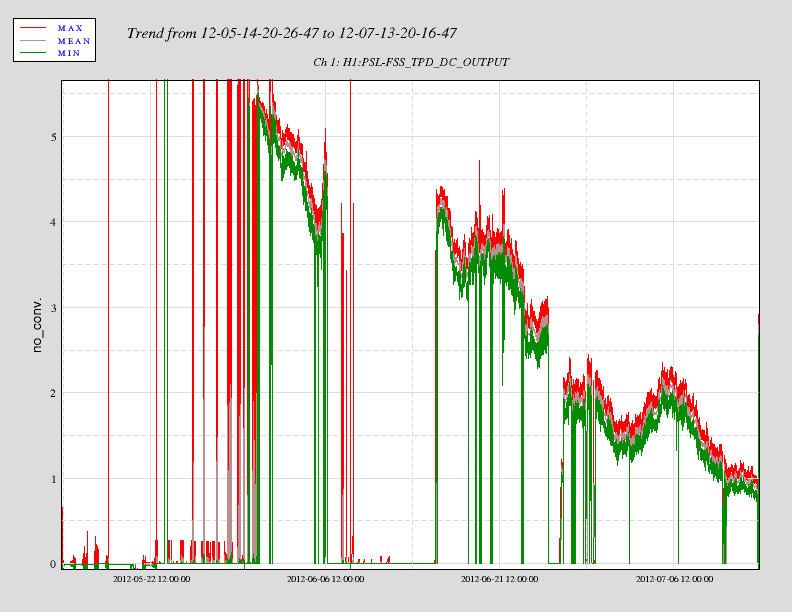
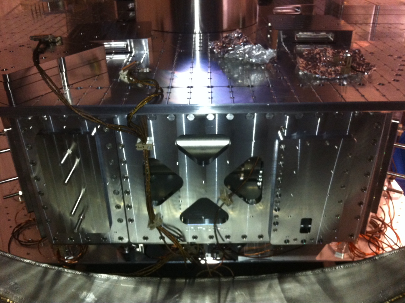
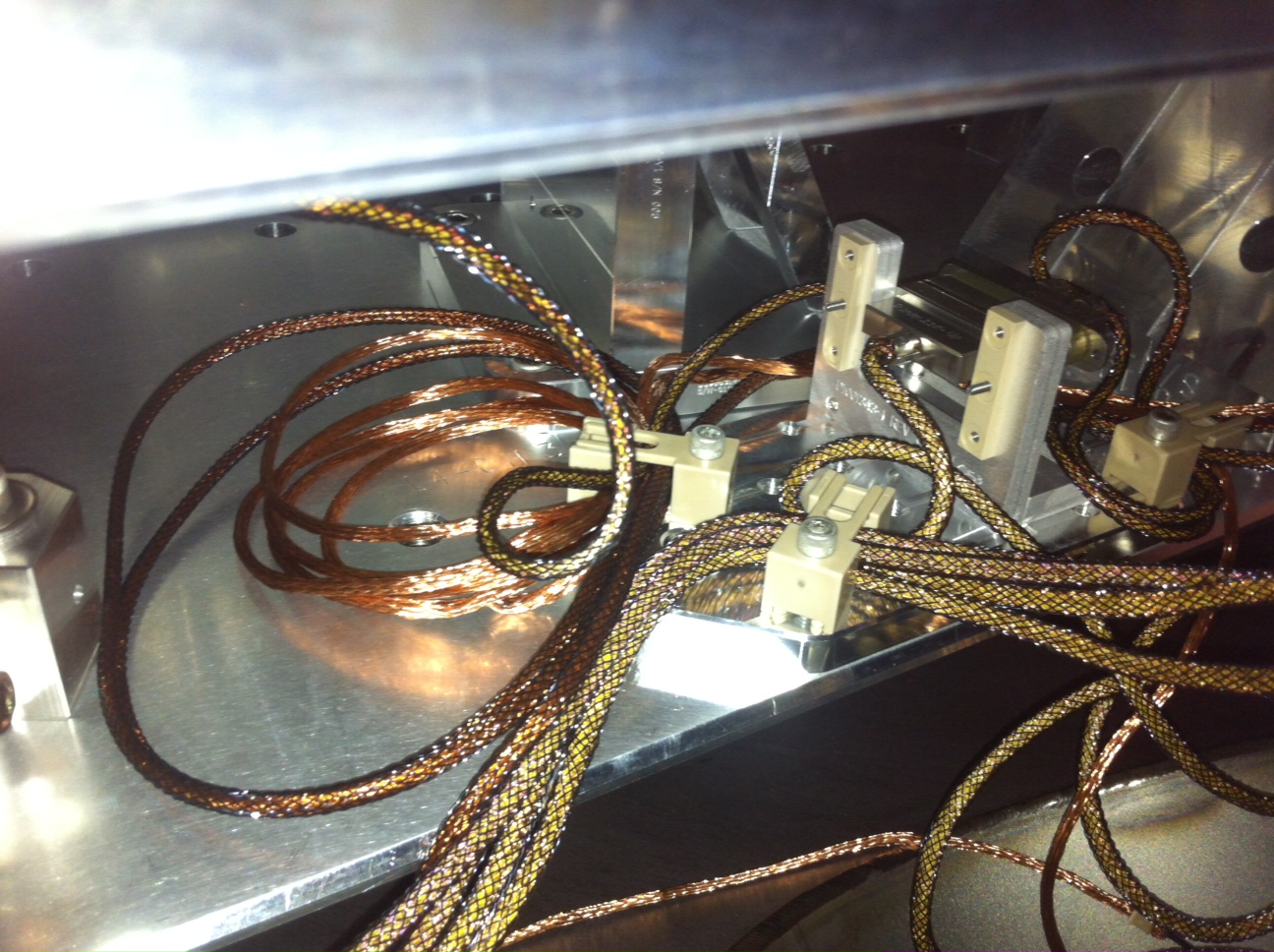
With septum-separated VE volumes vented, the ion pump controller achieves mid-scale current (with HAM3 East and West doors removed and with their annulus ports plugged with rubber stoppers).
M. Evan, J. Betzwieser, (J. Kissel) See LLO aLOG 3850, for details, but this may be why we've been having so much trouble with driving from the L2 Stage. This bug fix has not been implement yet on the LHO system, as we're waiting for the incoming updates from J. Kissel.
The following work was installed/powered last Friday: End Y H2 Electronics Rack (Receiving area entering EY) 1. 2 Magnetometers and 2 filter units 2. 1 Microphone 3. 1 Accelerometer and 1 Endevco Unit Two Kepco Power supplies were installed in the DCC Power Rack to power PEM units. LVEA ITMY Racks (Between BSC8 and Y arm manifold): 1. 3 Magnetometers 2. 3 Microphones 3. Accelerometers and 1 Endevco Unit
The ETM optical lever shows interference fringes when the TM is subject to a large longitudinal drive. I guess this will go away when the front surface beam is found, but it is something to look for on all the optical levers to be sure that we don't add noise from longitudinal motion.
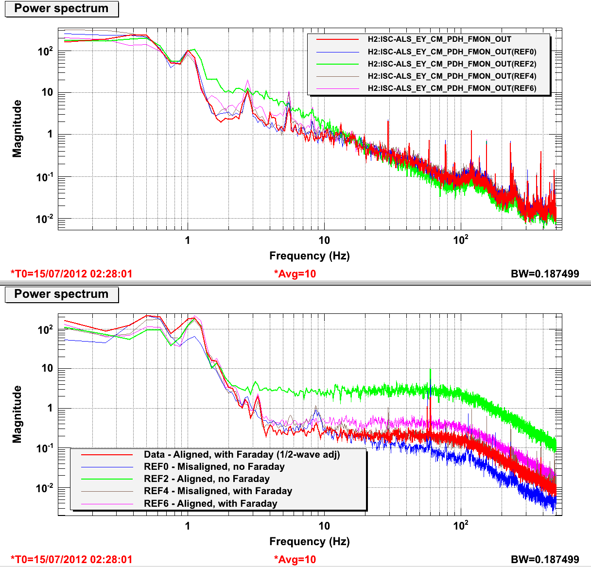
Due to an apparent increase in noise when the cavity was well aligned, we (Bram and Matt) suspected that some of the 532nm light retro-reflected from the cavity was getting into the laser and causing problems. To test this, we added a second faraday after the laser on the ALS table (ISCTEY) and realigned the beam. This appears to have had the desired effect (see plots), but in the process we discovered that some work will be needed to understand the REFL RF photodector, as it seems to be overfilled and its alignment may change our noise floor.
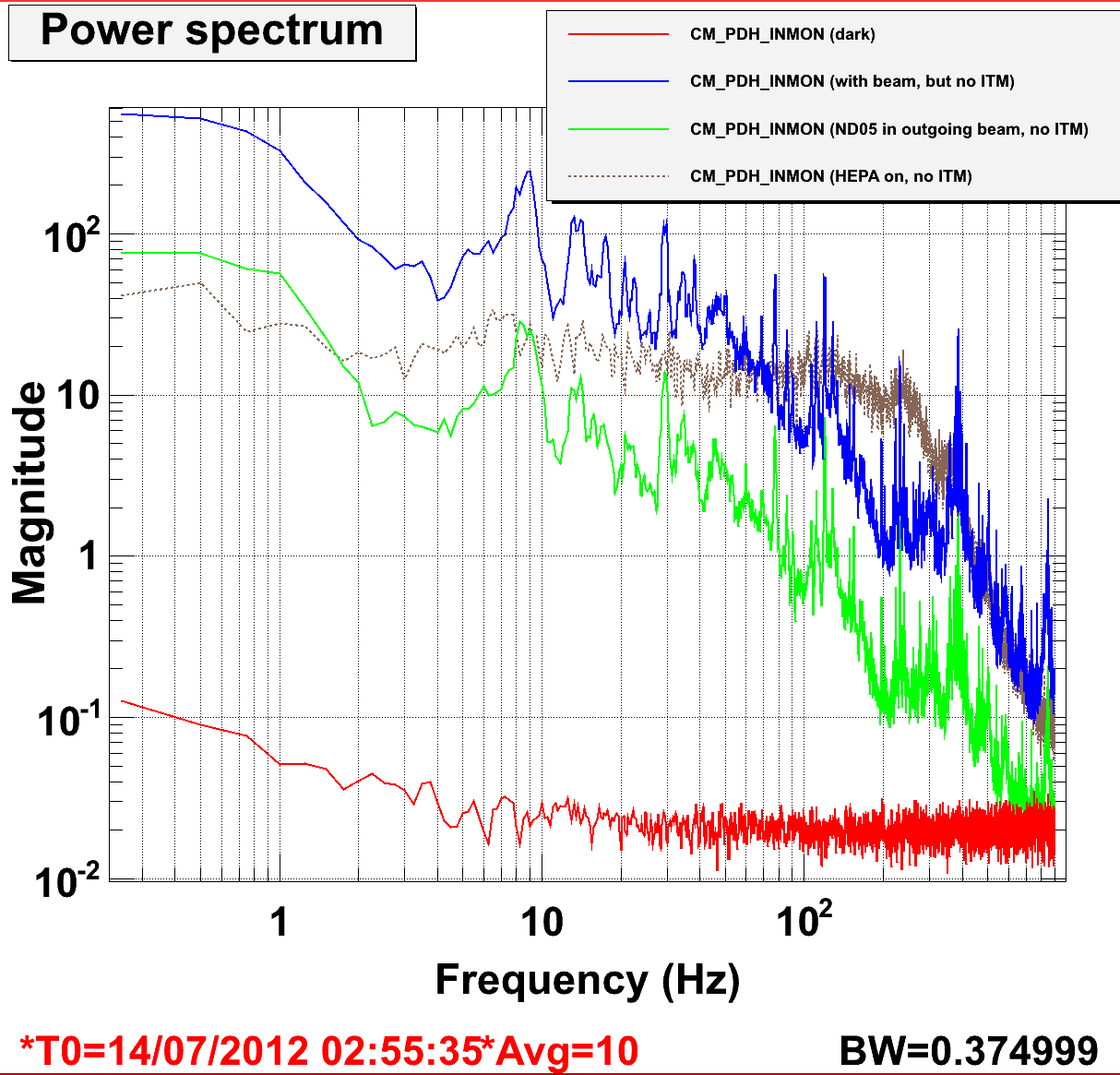
We also found clear fringes in the cavity error signal (PDH_IMON) even with the ITM misaligned. The fringe velocity is senstive to motion of the ASL table, and to the state of the HEPA fan on the table. These fringes are only a few mV, but they may be a noise source and will need to be investigated further.
In the lower plot of figure 1, the signal being plotted is REFL_PWR_MON_OUT. This signal comes from the PD which monitors the light reflected from the cavity.
The cavity is locked and operating normally as of 3:00 UTC (20:00 local). The ISCTEY HEPA fan is off.
The addition of a Faraday in the green laser path has reduced the operating power by about 20%, so REFL_PWR_MON_OUT between 5000 and 8000 indicates that the cavity is locked and reasonably aligned.
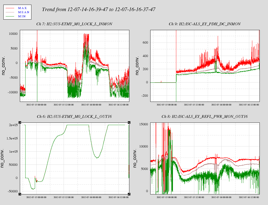
The cavity alignment degraded as the force applied to M0 on the ETM increased to the maximum value (200k in L, or 100k on each BOSEM). It was locked and well aligned for the first hour, and stayed locked for 10 hours (until 13:00 UTC) before the ETM hit the limits.
I tripped the EY HEPI the cavity locking process. I am not aware of a reset to 'working' scipt.
EY ISI and SUS where tripped as well. On both I resetted the watchdog and the daqkill .. all is well.
Example of "broken":
controls@opsws4:~ 7$ tdswrite -sw H2:HPI-ETMY_ISO_HP INPUT OFF
ERROR: can't read from H2:HPI-ETMY_ISO_HP_SW1R
controls@opsws4:~ 0$ ezcaswitch H2:HPI-ETMY_ISO_HP INPUT OFF
readback H2:HPI-ETMY_ISO_HP_SW1 not accessible
This make scripting difficult.
The cavity is locked and operating normally as of 4:15 UTC (21:15 local). The ISCTEY HEPA fan is off.
Attached are plots of dust counts > .5 microns in particles per cubic foot.
Robert and Maggie hooked up new ACC, MIC and MAG signals in both the LVEA and EY. At EY new signals were attached both to the h2pemey front end and the h2pemeyaux (Newtonian Noise) front end.
I build new models for h2peml0, h2pemey and h2pemeyaux and restarted them on the front ends h2tcsl0, h2pemey, h2pemeyaux respectively.
I then restarted the H2 DAQ to get the new channels into the frame.
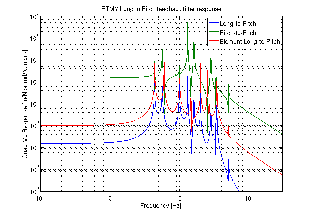
More detail will follow, but we determined how to get the length to pitch decoupling filter (jsut a confirmation), and using the Quad models we generated the length-to-pitch decoupling filter, for placement in the 'DriveAlign Matrix' in the M0 path.
The frequency dependent response is -Length-to-Pitch / Pitch-to-Pitch (with a gain factor).
Using plotallquad_dtttfs.m and quad_l2p.m in /ligo/svncommon/SusSVN/sus/trunk/QUAD/Common/MatlabTools, I generated Dl2p_2012_07_13.mat. Is has a frequency vector and the coupling vector.
I modified the script to include the M0 Long-2-Pitch and the Pitch-2-Pitch transfer functions as well.
Activities for the day:
- Kyle vacuum work at HAM03, 8:44 - 8:58 am.
- Robert and Maggie, then Filiberto joined, PEM work, YBM area. 8:55 - 9:52 am.
- Jim W. and Mitchell R. work at HAM02, 9:21 - 10:56 am.
- Eric A. in and out of the LVEA, to check are around HAM02 and HAM03, 9:29 - 9:31 am.
- Douglas D. in to LVEA to put tools away, in and out, 9:37 - 9:40 am.
- Sno Valley to service HVAC @ X-End, 10:00 am
- Michael R, work at PSL, 10:04 - 10:18 am.
- Ski, work at mechanical room, 10:00 - 10:23 am.
- Justin B. visit the LVEA and to read a gauge,
- Maggie, et.al. to visit Y-End station EE racks, PEM work.
- Spotted forklift, green one, driving away from OSB towards LSB, 11:38 am.
- Kyle, LVEA work at HAM06, read a gauge, 1:23 - 1:28 pm.
- Michael R. and Rick S. visit PSL racks, 11:00 - 2:00 pm.
- Mitchell R. work at HAM03, 1:51 - 3:10 pm.
- Dominick, Y-End cable work at EE racks, 2:00 pm
- Received one momentarily dust alarm.
Rick S, Michael R
The 1k resistors R80, R85 in the FAST path and R71, R76 in the COMMON path were swapped out with 2k resistors to access a full range of gain. The gain in the medm filters for these paths was adjusted from 2048 to 1024 to compensate.
After the box was reinstalled on the table with the original medm slider gain settings (23dB for common, 8dB for fast) we found the UGF had changed and couldn't quite be recovered by using the gain slider. We found that the transmitted PD was low, only reading about 1V, and has been trending down the past few months from 5V. A quick alignment touch up of the periscope mirrors (in vertical) upstream of the ref cav increased the voltage to 2.8, but more work on the FSS path is needed to recover the lost light. We settled at 25dB for common gain.
The RFPD DC signal is dead so we can't compare the reflected to transmitted.
(corey, mitch) [this work was for Thursday 7/12]
While there was a lot of HEPI hustle and bustle at HAM3, Mitch and I took the opportunity to do cabling work on HAM2. For SEI, most of the cabling has been run, but I cleaned it up a little bit (especially the insanely inaccessible Corner3 path). I also installed our grounding/mounting brackets for our GS13s. For Corner3 work, I actually went in-chamber, climbed on table and hung out in the beam tube for this work---it wasn't that bad as far as access.
Mitch had cabling for SUS & ISC, so we went ahead and started running these cables (per a drawing which escapes me). We started on the west side, and I did a couple of cables on the north side, while I was in the chamber. We finished off getting ready to do the east side, but ran out of time. I'd say we completed about 75% of the SUS/ISC cabling.
Now while handling some of these cables, I noticed that one of the (4) screws on the face of the connector fell out. I checked the other screws and they were all a bit loose (a half/full turn), so I went ahead and tightened all of them.
Cleanliness note: Will these chambers get vacuumed again? While in chamber I noticed particles in the bellows (a piece of glove, and a fairly big (1-2mm) plastic piece).
A quick check of ITMY (push in a length offset and remove it) show no signs of fringes.