I removed the final Horiz & Vert Actuators from BSC4's SW corner. All of these Actuators are on pallets out near BSC3, for installation on H1 HEPI locations. The crane is parked in its normal parking spot.
It turns out that most of the power in the HWS path is just dumped. We installed a PDA55 to monitor this otherwise wasted beam so that we can measure the reflected beam power without being clipped.
According to this PD our contrast (1-min(locked)/unlocked) is 65%. I'm taking min(locked) because, when locked, the REFL power fluctuates much because of the alignment fluctuation (but not clipping).
We can refine alignment further, but doing it manually is no fun. We're working on WFS. Also, though there's no fast ADC monitoring the refl DC, we might be able to auto-dither connecting REFL DC to AUX channels.
Attached are plots of dust counts > .5 microns in particles per cubic foot. I have also included plots of the modes for a dust monitor in the optics labs, LVEA and end Y. The connection to the dust monitors in the optics labs was lost. The IOC was restarted in the evening.
Mitch, Corey, Hugo,
Quick TFs were taken in the morning. They shown 1/2 gains on L4C-V1 and GS13-V2. The other main issue was the presence of a high-Q resonnance at 237Hz, on the Actuator-H1--to--GS13-H1 TF.
Transfer Functions measurements are running overnight.
~9:30AM - craning work begins in the LVEA for ISI HEPI ~10:43AM - craning work completed Work beginning in the morning at End-Y for OAT cavity locking lasted until the late afternoon.
Briefly ran purge air skid to shut-down QDP80. MTP rotor still levitated, i.e. controller still is energized - will de-energize later
(corey, eric)
With a craning window until 11am, Eric and I continued removing H2 Actuators. We removed Horiz/Vert HEPI Actuators on BSC4's NE & NW corners. We staged for removing the final pair of Actuators at the SW corner.
It would appear that someone shut off the coil driver chassis for the L2 stage of the ETMy thus causing the ill functioning OSEMS noted by Keita. If you trend the the channels on DV you can see the channels going down for the new resistors for the BIO channels on6/15 then on 6/22 the channels go down again where they stayed until this AM when Fil and I powered the chassis back up using the on/off switch on the back. We also took this opportunity to verify the BIO are functioning. We put offsets on the Coils in software and measured at the output of the coil driver. With a 1 in the appropriate field we saw signal with an 0 on that field we saw the output drop to~zero. In the control room I could see the offset signals on the OSEMS if I drove it very hard.
PDH locking is much more reliable due to improved alignment.
Its UGF is about 9 kHz with the current setting, but we can set it higher (up to 13 kHz) or lower without touching PLL.
There's some high frequency (about 250kHz) noise in the PDH error signal, which is likely from the PLL.
PLL UGF is also about 9 kHz, which is limited by the PZT resonances (f>100kHz). We'll have to modify the CM board.
We tried to use green WFSs. First we found that there was no bias voltage source so we put an old iLIGO bias unit. Then we found that the WFS DC interface was not working in Beckhoff world and centering the WFS was hopeless. No PDH DC in Beckhoff, either. We're working on these.
Suspension damping got better than when we started, but the DC level on the PDH diode, depending on the alignment, still fluctuates due to clipping in/on the Faraday by as much as 50%. Better PDH lock means that the cavity wouldn't lose lock with this, but it's a problem nevertheless. For example it's difficult to assess how good or bad the matching is quantitatively. In-lock to out-of-lock ratio of the maximum DC level of the PDH diode was somewhat better than 50%. Better SUS damping AND larger aperture Faraday should help.
Alexa and Patrick are making some progress and most of slow things in Beckhoff world are being passed to EPICS world already (a notable exception is CM board). Not everything has been tested, though.
Michael Thomas (LLO CDS sysadmin) visited last week (June 25-29). Abe Singer (LIGO cybersecurity) also visited (June 26-28).
With Abe we (Michael, Dave, Jim) discussed the current status of the CDS security system, and we held an OCSC meeting.
With Michael we discussed the current differences between the LHO and LLO sysadmin systems, with the aim of documenting the differences (and perhaps removing them).
We constructed a network management system at LHO (using Nagios) to be identical to the one Michael installed at LLO. We (Dave and Jim) will work on ensuring in all our networked systems are monitored by Nagios.
A leap second was added to UTC at midnight UTC time yesterday (17:00 local time). I was on site and watched the control room clock, which dissapointingly did not show the "60" second.
I tested the IRIGB ADC channel on the H2 DAQ frame and verified it is now indeed 16 seconds off UTC (was 15 seconds off prior to the adjustment). Daniel showed that the IRIGB timing unit in the MSR had extinguished its "leap second pending" LED and was now reporting 16 leap seconds between UTC and GPS.
Greg verified that the frame did not increment its GPS-TAI difference
ULeapS stayed at 34 (it should be 35)
This is causing some problems with the frame verification programs
$ /usr/bin/framecpp_verify --verbose
VerifyException: METADATA_INVALID: Bad ULeapS value ( for gpstime: 1025136600.000000000 expected: 35 read: 34 )
We will work with Alex on upgrading frame cpp on the frame writers to permit ULeapS to be corrected.
Szymon and Mark Tests announced earlier are complete. Damping is back on. We were a bit hampered by the dead L2 AOSEMs on ETMy but otherwise got what we needed.
ETMY L2 OSEMs are all showing zero-ish number in IN1 channels.
I and Jax looked at Birmingham field boxes in EY (we found 7 total) and one of them seems as if it's not powered though we have no idea if this box is connected to ETMY L2. The cables attached to this box were H2 SUS ETMY 19, 20 and 21.
Szymon and Mark. When Keita et al. are done for the evening (6 pm or so), we plan to do run tests to get data for diagonalizing the OSEMs, especially the L2 AOSEMs which are pretty bad at present. This will consist of: Turn off damping on the main chain. Excite longitudinal pitch and yaw modes by temporarily adding offsets to the M0 test filters. Take a power spectrum. Restore damping. We plan to do ITMy first and proceed to ETMy if we get decent data and it's not too late.
Jim Greg Eric & Hugh The system was lifted off the stops and floated on the DSCW Springs. There appears to be some interesting twisting of the Crossbeam as the lift point changes moment arm length. The dial indicators outboard on the Support Tubes register lowering as we loaded the Springs. After confirming the float state, the Optical Table was surveyed again. It will take a few to digest the DI & Survey data to tell a better story but it should hold together. We did re-constrain the system with the EQ stops in case anyone needs to tramp about on the external system. But please don't if you don't need too. *** Also, please be very mindful of the dial indicators which are relatively low tucked underneath the Crossbeams. They should be out of the way but big floppy shoe covers my do unseen disturbing.
Remove oldest frame files from tripleteststand and seiteststand2 to reduce file system usage to safe level. (general maintenance)
J. Kissel, M. Evans As the QUAD damping loops have evolved over the past few days, I've taken open loop gain TFs of the latest configuration that we believe to give us the most reduced motion thus fair (as measured by the TOP mass -- which may not be the right figure of merit). The first three attached are the results for the three degrees of freedom in question. We can see that we have indeed significantly increased the amount of L damping, but P and Y have not changed that much, given the combination of adding boost filters at low frequency and decreasing gain. The fourth attachment compares the components of each of the filters, just give a rough idea of the shape and frequency of the boost filters. I also add on as bonus information (pgs 4 and 5 of the fourth attachment) the filters used for the TMSY, designed by M. Evans. Granted, he's got a much more simple suspension to deal with so he can be more aggressive, but we could maybe learn a lesson or two from his design. Specifically, instead of the B. Shapiro tactic of fixing the elliptical filter at 50Hz and trying to gain damping gain by lowering the "turn-over" poles of the baseline AC-coupling filter (the FM1s), M. Evans fixes the poles and zeros of his baseline turn-over, then tailors his elliptic to push hard on the performance. The advantage there is that, if you don't care about noise, you always have a configuration (FM1 only) which is unconditionally stable with which you can turn the gain knob arbitrarily. This is not necessarily true for the B. Shapiro designs. Back to the OLG TFs: The second attachment shows that we're probably squishing the Pitch just as much as before. As mentioned in my previous entry, this may mean we're locking the TOP mass to the Cage (in Pitch), and directly shorting the isolation of that stage. A quick fix to test this would be to lower the pitch gain by another factor of 3. See if it helps! Regarding the right figure of merit -- it seems like the UIM and below are showing little improvement. Perhaps, when one data mines the spectra for the times mentioned below, we should see how the UIM and PUM perform with respect to the TOP and the various configurations. Note, that in the 4th page of the first 2 attachements I show the OLG TFs of not only L to L and P to P, but the cross degrees of freedom as well. These OLG TFs are a better way of comparing relative amplitudes, because they're in the same units. BUT the measurements were taken with the damping loops OFF, so the off-diagonal terms show the situation with no P damping -- which shows that the L to P cross-coupling is horrendous -- but it's not representative of the real situation. The next measurement to do, would be to take the same measurement with damping loops CLOSED, and derive the open loop gains by measuring IN1/IN2 (another pioneering measurement). I'm out next week, so I may have to have someone do this one site .... or y'all can continue to play around, and see what you get. Best of luck!!
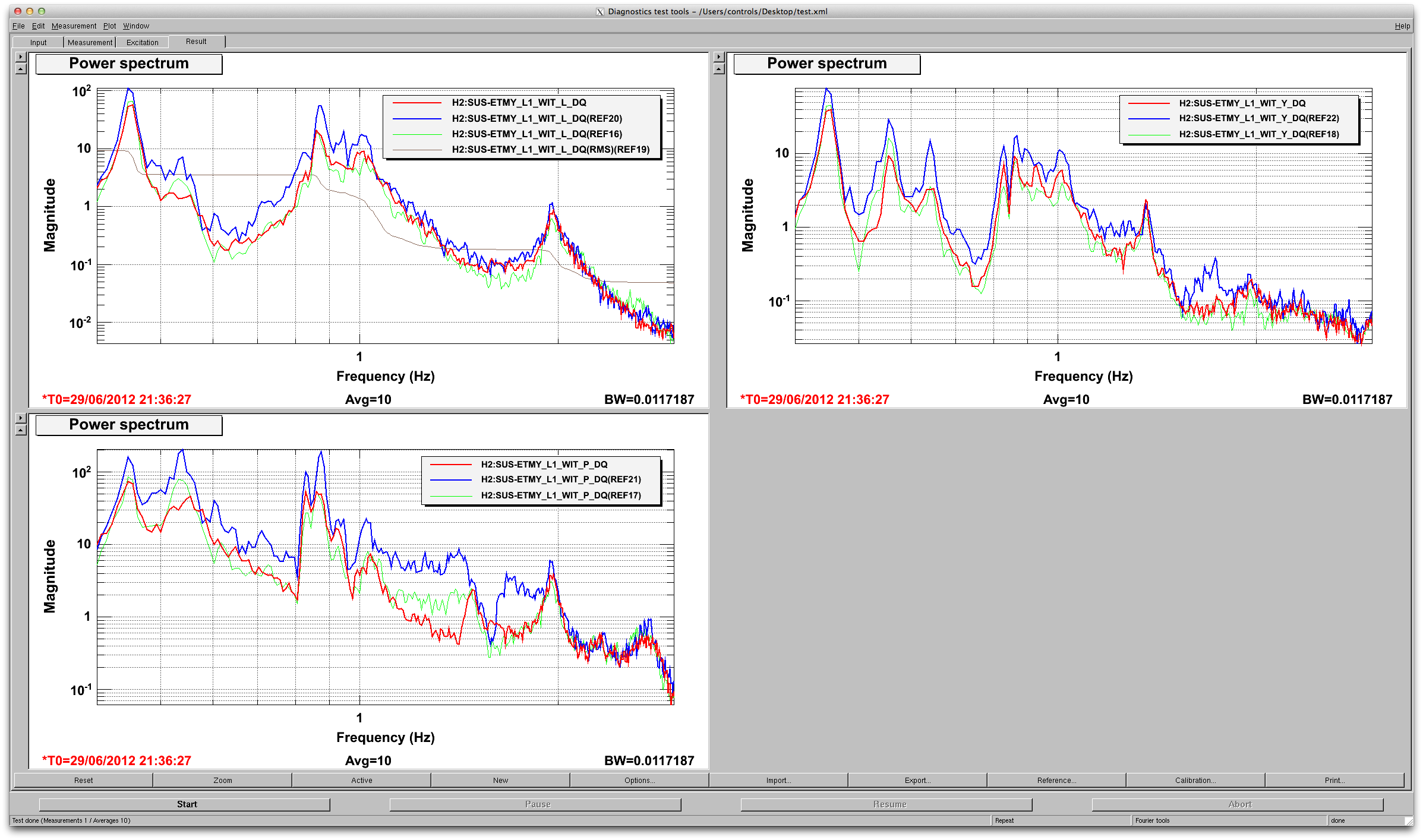
I've configured H2 SUS ITMY this morning in various states damping that we've developed over the past few days. I'll post the results later, but for future data mining:
All data taken with BSC8-HPI ON (IPS Loops only), and BSC8-ISI ON (Damping loops only).
Time H2SUSITMY Damping Loop Status Gains [L,T,V,R,P,Y]
(1) Jun 29 2012 (13:45 - 14:07) UTC Damps ON, Baseline Filters and Boosts ON [-20, -5, -2, -0.3, -0.033, -0.1]
(2) Jun 29 2012 (14:10 - 14:33) UTC Damps ON, Baseline Filters and Boosts ON [-10, -5, -2, -0.3, -0.033, -0.1]
(3) Jun 29 2012 (14:35 - 14:57) UTC Damps ON, Baseline Filters only [-10, -5, -2, -0.3, -0.033, -0.1]
(4) Jun 29 2012 (15:00 - 15:23) UTC Damps ON, Baseline Filters only [ -1, -5, -2, -0.3, -0.1, -0.1]
(5) Jun 29 2012 (15:25 - 15:40) UTC Damps OFF
The hope is that measuring these configurations back-to-back, over the course of a quiet morning (times are ) will give a better representation of their relative amplitude difference.
Also, just an update from B Team think tank:
We took some open loop gains from this morning on ETMY as well. Data to come, but it looks like, after adding the low frequency boost, we're back at LOTS of pitch gain, even with -0.03. The theory now is that because we're squashing pitch so hard, we've effectively locked the TOP mass to the cage, therefore creating a triple pendulum in pitch the directly transmits ISI input motion.
Hence, another quick fix to try would be to reduce the Pitch by another factor of three (leaving all else the same as config (1) above), for a total reduction from original by a factor of 10, from -0.1 to -0.01.