We performed the final test stand alignments for the BSC08 Quad today. Pitch was adjusted on the ITM and the ITM/CP gap was measured and the parallelism set.
This was the last of the test stand alignments. The cartridge has now been handed off to the testers to complete required tests before the cartridge install.
After the primary Initial Alignment calcs, moves, adjustments had been made, Betsy removed many SUS or IAS things from the Optical Table this morning and handed it back to SEI. We ended up adding 7-1/4kg (~16lbs) to Stage2 to re-balance. Our lock/unlock motion is within specification so we hand the Cartridge Assembly back to SUS/IAS for final tweaking before testing. Jim/Hugh
J. Garcia, J. Kissel Jeff G.'s taken another round of measurements after the following:- The BSC-ISI is floating! - After all (er most?) of IAS adjustments have been made - Stiffening elements have been put on - Vibration absorbers have been put on - L1 (UIM) and L2 (PUM) OSEMs have been aligned, and masses have been re-balanced accordinginglyResults look really good! More analysis to come, but I attached the results. This chain has had no where near as much trouble as the main chain; any problems that we did have were focused on the stiffness of the reaction cabling. It looks like what we have in place now has been consistent and like the model for the past two measurements. As long as nothing changes (other than locking and unlocking before and after the cartridge install) I approve this chain!@
I have removed the H1 PSL dust monitor and unplugged the external vacuum pump for it in the mechanical room.
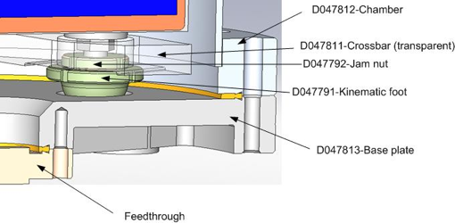
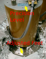
Non-final podded seismometers were being used for testing on our completed HAM assembly. Last week a horizontal unit wasn't functioning correctly, it would respond to large inputs but damp very quickly. I thought this would most likely be caused by a mass that was uncentered. Luckily for us this particular seismometer was going back to Livingston anyway, so Vincent and I popped the vacuum pod and removed the GS-13. While doing this I noticed the crossbar on one edge was noticeably looser than the others and was most likely due to a kinematic foot backing up the threaded rod. This tilt would be enough to rail the seismometer's mass. While the can was off the base plate Vincent and I double checked the flexures to see if any of them had loosened or broken, but they were all in good shape. Since we don't have an angle bracket to re-level the horizontal GS-13s to the base plate I hoped that the top of the seismometer was perpendicular enough to the mass to level from that. With the GS-13 back on the base plate and a precision level on top of the GS-13 I adjusted the kinematic feet to obtain a level (again hopefully perpendicular) within 80-90 seconds. Then I locked down the jam nuts and hand tightened the crossbars. After sealing the top hat back onto the base plate I realized I probably should have taken pictures, then I freaked out and wondered if I unlocked the mass. After reinstalling the pod onto HAM 1 Vincent checked the refurbished GS-13's frequency response to the others and everything looked good. This definitely seemed to be an issue with either a loose jam nut or an insufficiently tightened crossbar. These testing seismometers saw quite a bit of abuse with how much they had been removed and reinstalled but extra care should be paid attention to these feet as having to deal with a bad GS-13 in vacuum will be a significantly larger headache.
J. Kissel, B. Shapiro, J. Garcia
After some mechanical adjustments on H2 SUS ITMY M0 made by the assembly team,
- F1 flag dis- and re- assembly at TOP stage
- Moving mass forward on UIM
- Recovering UIM and PUM signals, aligning flags,
Jeff G. has taken another set of transfer functions to asses how we did (Last Tuesday, 2011-11-29). In summary, the main chain looks better (but still not great -- Pitch as usual) but not as good as we'd like. We believe there are several issues going on:
- The dynamics are different from the model, because the d's between the top stage and the UIM stage (parameters dn and d1) are not dead on. (yellow flag)
- The large offset in the UIM ballast mass (i.e. having it fully forward (HR side)), is causing that stage's horizontal center of mass to be offset from the center line of the suspension (represented by h1). (yellow flag)
- The overall magnitude of the Pitch transfer functions are a ~50% lower than the model. (yellow flag) This may just be the accuracy of the measurement calibration factor.
- There is an excessive amount of Longitudinal coupling into Pitch. This has been reduced with Travis flag dis- and re- assembly, but some cross coupling still remains. (red flag)
I attached four plots for your perusal. All are M0 TOP to TOP transfer functions.
(1)allquads_111130_H2SUSITMY_ALLM0_TFs.pdf
Comparison between nominal model (BLUE) previous main chain measurements (ORANGE), and current main chain measurements (BLACK). Note that 2011-11-19 measurements of V and R are missing, because the M0RT OSEM had failed. We see hear, as before, that the degrees of freedom (besides Pitch) all line up quite well with the model, implying that the majority of the dynamics in the suspension are free and well.
(2)2011-11-29v2011-11-19_H2SUSITMY_M0_P-P_TF.pdf
Zoom Comparison between nominal Fiber model, the first 2011-11-19 measurement, and the current 2011-11-29 measurement. Here, we see the good news that the severe cross-coupling between L and P has been reduced, but not to what we expect from the model (and from what we've seen on metal builds).
(3)2011-11-29v2011-11-19_H2SUSITMY_M0_P-L_TF.pdf
Model, 2011-11-29, and 2011-11-19 Pitch to Longitudinal cross coupling (compared against 2011-11-29 and 2011-11-19 Pitch to Pitch), quantifying the reduction.
(4)2011-11-29v2011-11-19_H2SUSITMY_M0_P-P_TF_modelcomp.pdf
Comparison between models with parameters varied, in order to try to explain what might be happening with the dynamics and the yellow flags mentioned above. I've tried moving around two parameters that we believe might effect the dynamics as we've seen (motivated by physical differences).
fiber = Nominal Model, with h1 = 0 mm, and both dn and d1 = 1 mm
fiber_h1plus5mm = Modified model, with h1 = +5 mm
fiber_dnd1plus1mm = Modified model, with dn and d1 = 2 mm (break off points are further away from the vertical center of mass, dn increased in +Z, d1 is increased in -Z)
fiber_fiber_h15mm_dnd11mm = Modified model, with both h1 = +5mm, and dn=d1=2mm
Again, we suspect that h1 is offset because there's a good fraction of the ballast mass on the HR side of the UIM, and we suspect the d's concerning the UIM might be off, because they (a) affect the two modes that are the most different in the model, and (b) these d's are adjustable, and are defined by blade tip heights a physical parameter difficult to mail down. One can see that, though both parameters effect the dynamics differently, the combination of the two explain the measurement quite well, specifically offsetting the horizontal center of mass at the UIM explains some of the high-frequency cross-coupled length resonances.
-----------------------
Our best guess up to this point as to where the remaining cross-coupling is originating from is that F1 is not driving as much as we think. The idea being that we intend drive equally in (F2+F3) and F1, and because either the F1 (a) electronics, or (b) the OSEM coil-magnet pair results in less drive in F1, there is an imbalance in the drive, and (F2+F3) ends up driving more, which means that Length is excited more than expected.
Things I'm looking into in order investigate this claim:
- Looking at F1 response in a Length drive, compared against models. The thought is perhaps the monolithic is more susceptible to this particular flaw, so comparisons against metal builds may not be as enlightening, but we can check anyways. If there's a large discrepancy, this would indicate that the sensing part of the OSEM is at fault.
- Comparing Pitch / F1 response to reaction chains. The TOP and UIM masses are identical between the two chains, and should therefore have the same mass. Further, the total mass of the two chains is identical. This means at high frequency, above the resonances, where the transfer function should be just as a free mass (F = m a, or T = I a), the chains should be the same.
Measurements we can do in order to better identify the problem
- Measure the OSEM basis (F1 to F1, F2 to F2, etc) transfer functions, and compare against the model (~2 hours of measurement, 1 days worth of analysis). If the F1 to L check doesn't turn up anything, then if this comparison with model shows something strange, then we know it's the actuator side of the OSEM that's failing.
- Measure the F1 response at DC (at a few different drive levels, using offsets in the COILOUTF banks), then replace the OSEM with a new OSEM from "off the shelf," and perform the same measurement. (1/2-a-day of measurement, 1/2-a-day of analysis) If there's any change, you know it was the bad OSEM. If there's no change, then we know the OSEM coil-magnet pair is OK, and it's some further flaw upstream in the electronics.
- If the OSEM turns out not to the be the problem, we can drive equal amounts of digital signal from the DAC, and measure the response at the mock in-vacuum feedthrough. (1/2-a-day of measurement, 1/2-a-day of analysis).
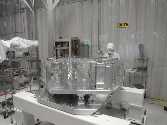
Couple Photos and brief report here. First, the ISI is carefully placed back on the Test Stand. The second photo shows the rebuilt Stage1 back on the Stage0. The HAM 9 unit is currently undergoing testing. The HAM8 unit (shown in these photos) will have its Springs pulled down today quickly followed by the installation of the Optical Table. Jim, Corey, Mitchell, Greg, Eric, & Hugh
TheH2:SUS-ITMY_*_COILOUTF_*_GAINchannels were modified on the R0 chain such that a positive drive from the Euler-basis coil outputs induced a positive response in the Euler-basisH2:SUS-ITMY_*_DAMP_*_IN1_DQOSEM readback channels. For theH2:SUS-ITMY_M0_COILOUTF_*_GAINchannels: F1 = 1.0 F2 = 1.0 F3 = -1.0 LF = -1.0 RT = 1.0 SD = -1.0 For theH2:SUS-ITMY_R0_COILOUTF_*_GAINchannels: F1 = 1.0 F2 = 1.0 F3 = -1.0 LF = 1.0 RT = -1.0 SD = -1.0
Found the 6.7mm error this morning. The error was not in the EDM measurement, but in the design of the corner cube mount. As the mount is currently designed, we touch off of a metal plate that is sandwiched between the corner cube and the XY translation stage of the mount with a CMM to accurately measure the distance between this metal plate and the ITM; this gives us the distance we need to add to the EDM measurement to get the total distance from the total station to the ITM (the EDM from the total station only measures to the corner cube). This plate was thought to be at the back plane of the corner cube (most corner cubes have a constant that is the offset distance from the virtual focus of the coner cube to its back plane and this distance must be compensated for when using a corner cube for EDM; our corner cube has a 30mm constant) but in actuality the back plane of the corner cube is 10mm inside the metal plate. This subtracted 10mm from the measured distance, indicating that the structure had to be moved in the -y direction. We will start considering a redesign of the corner cube mount, but in the short term we were able to compensate for this using the total station. The total station has the ability to automatically compensate for a corner cube constant, therefore we simply changed the constant from the 30mm we were using (since it was a 30mm prism constant) to 20mm, which represents the distance from the coner cube virtual focus to the front surface of the metal plate. This also means that the FM, which was thought to have been 12.7mm too far forward, is only 2.7mm off of its ideal longitudinal position, which is within the ±3mm of error set out in E1100690.
As a result of today's work, we determined that no more structure moves are necessary and we can continue with the fine pitch and yaw alignments.
Signage at LVEA card reader requested noise source logging
Because I don't see a current a log, I'm posting what I know for today. On Friday afternoon we completed adding the balance of the SUS payload to the ISI table. The SEI crew then balanced the table but left it locked so we could make a round of Romer arm measurements on the ITMy. Still hunting for the ~6mm y-axis error, we made some measurements of the upper structure structure relative to the ITMy HR surface. We have had some manufacture errors with these upper structures, so we wondered if there were more that we had not found. At first glance, based on these measurements, the suspension position within the structure does not seem to be the source of our error. The ISI was unlocked and the suspensions unclamped for the night. I believe Garcia and Vincent were going to start testing the systems but I'm not sure their status. Today, Dennis continued the 6mm hunt by looking at our alignment templates which were used when fixing the ITMy to the table. These do not appear to be the source either. As of discussions this afternoon Dennis, Doug, and Jason anticipate working tomorrow morning to redo the EDM measurements.
Bram, Valera, Matt
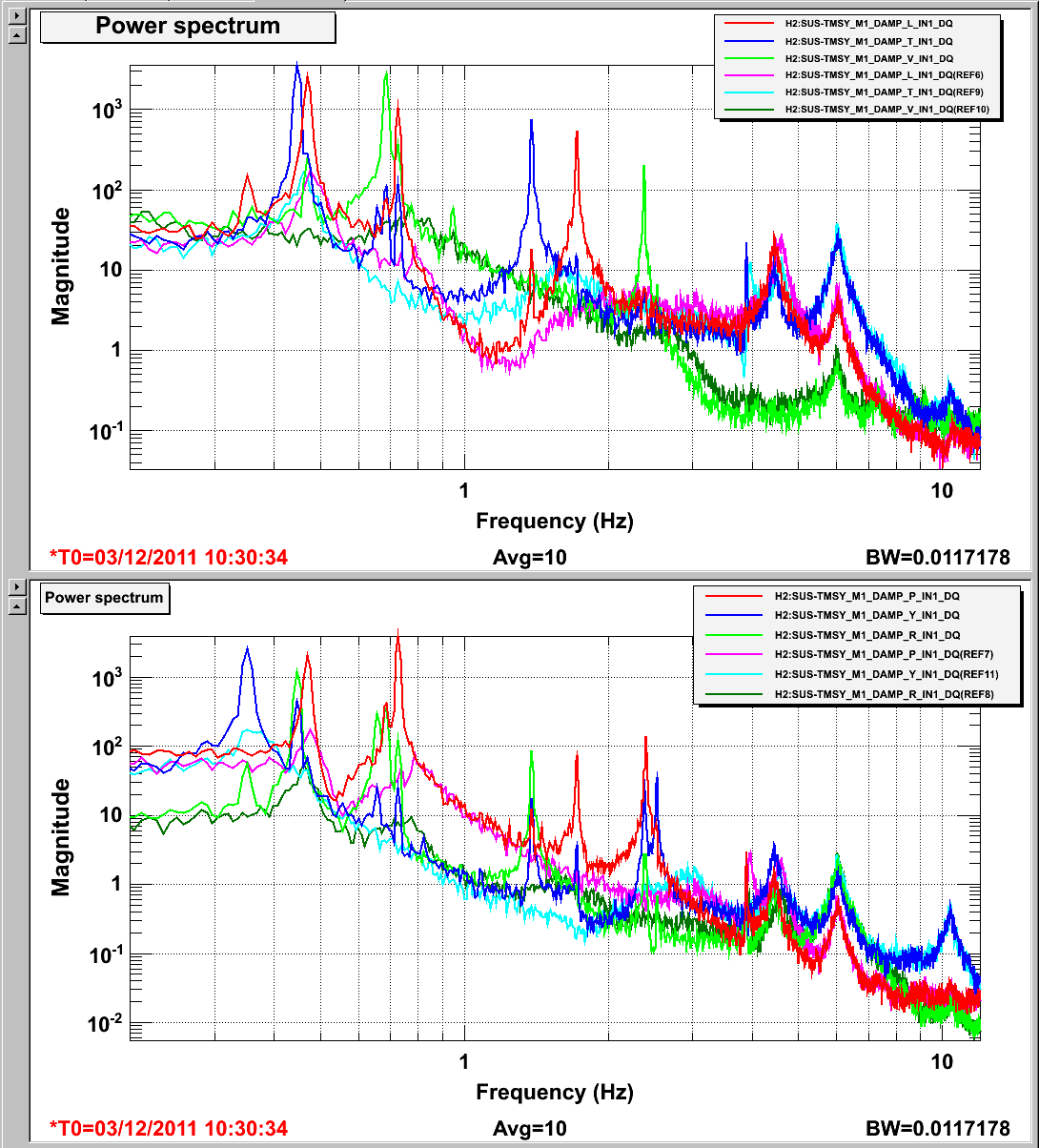
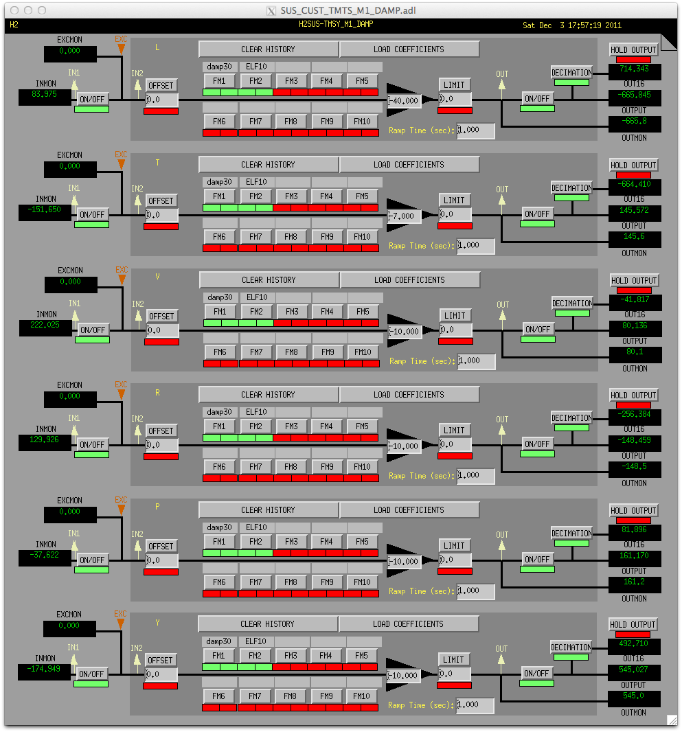
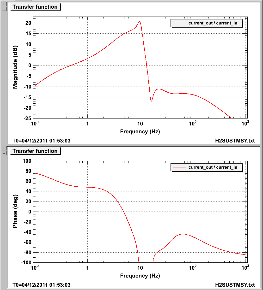
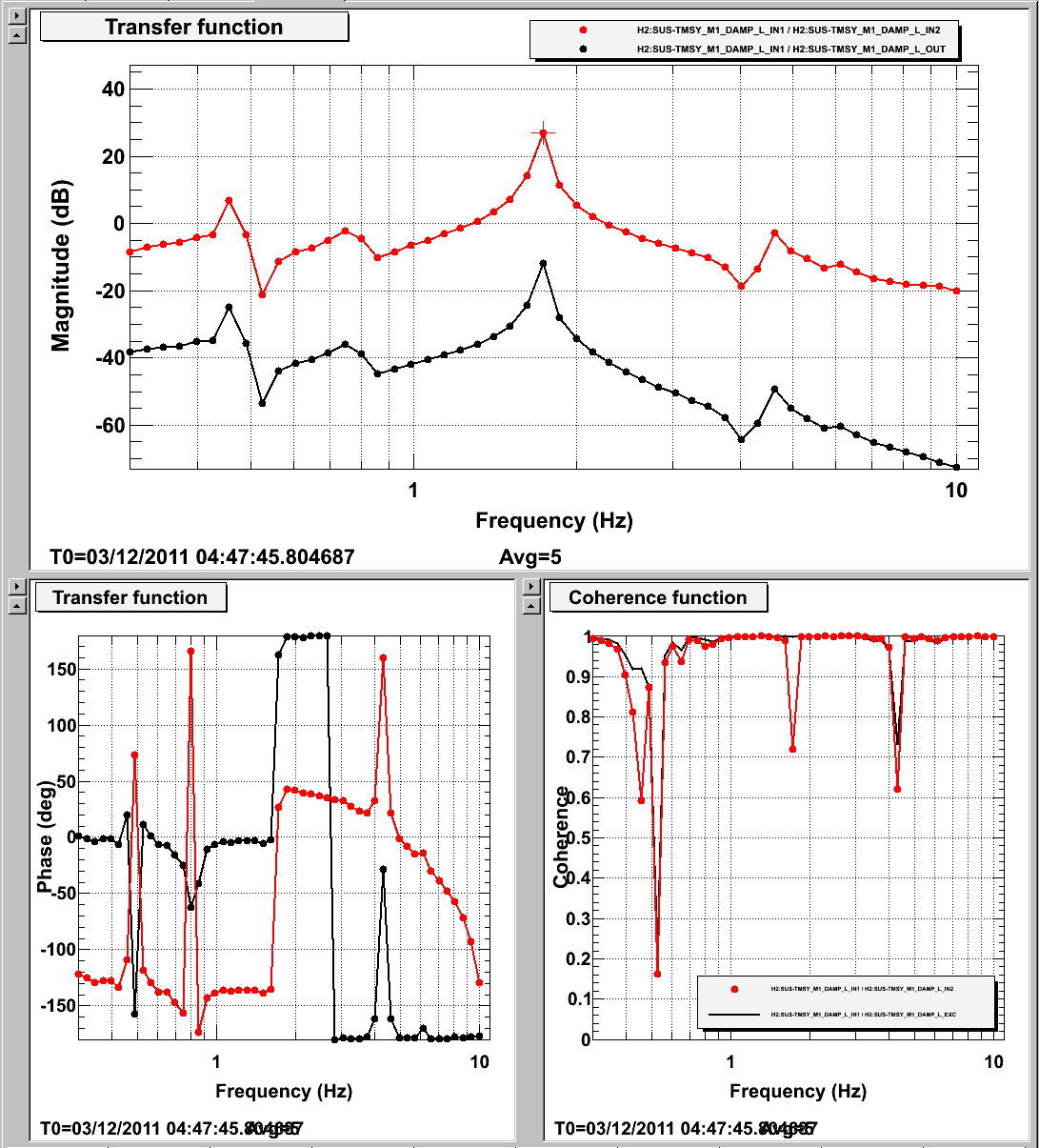
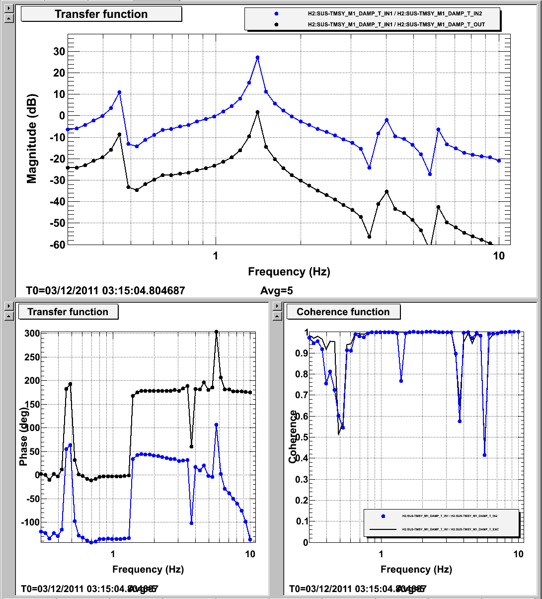
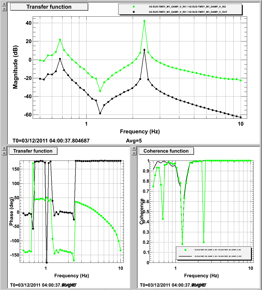
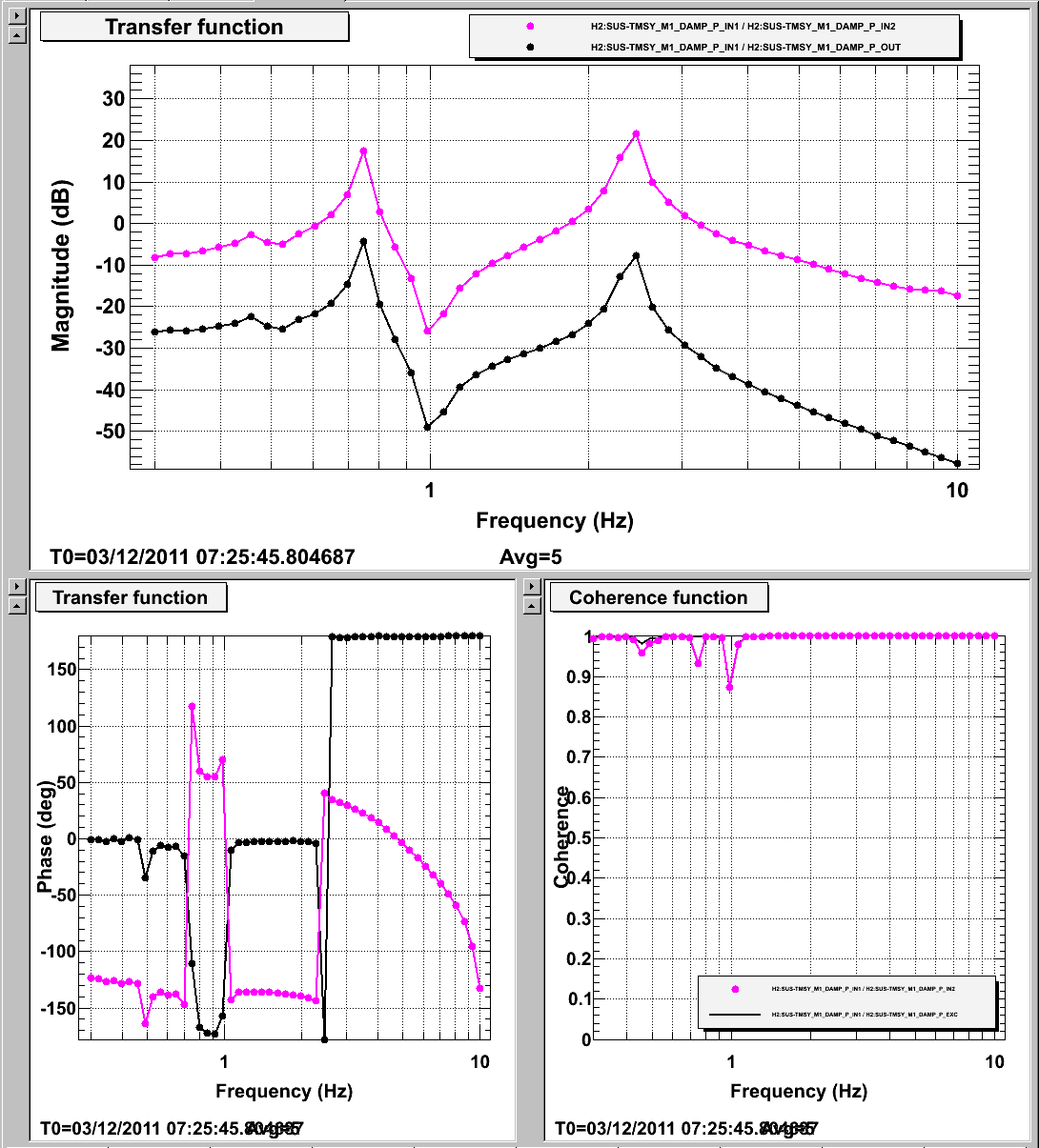
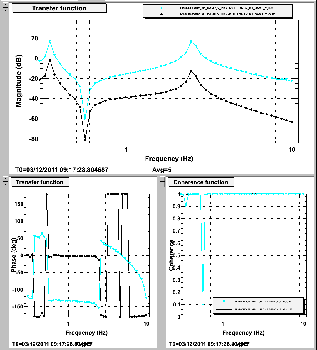
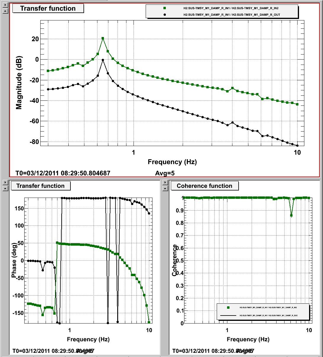
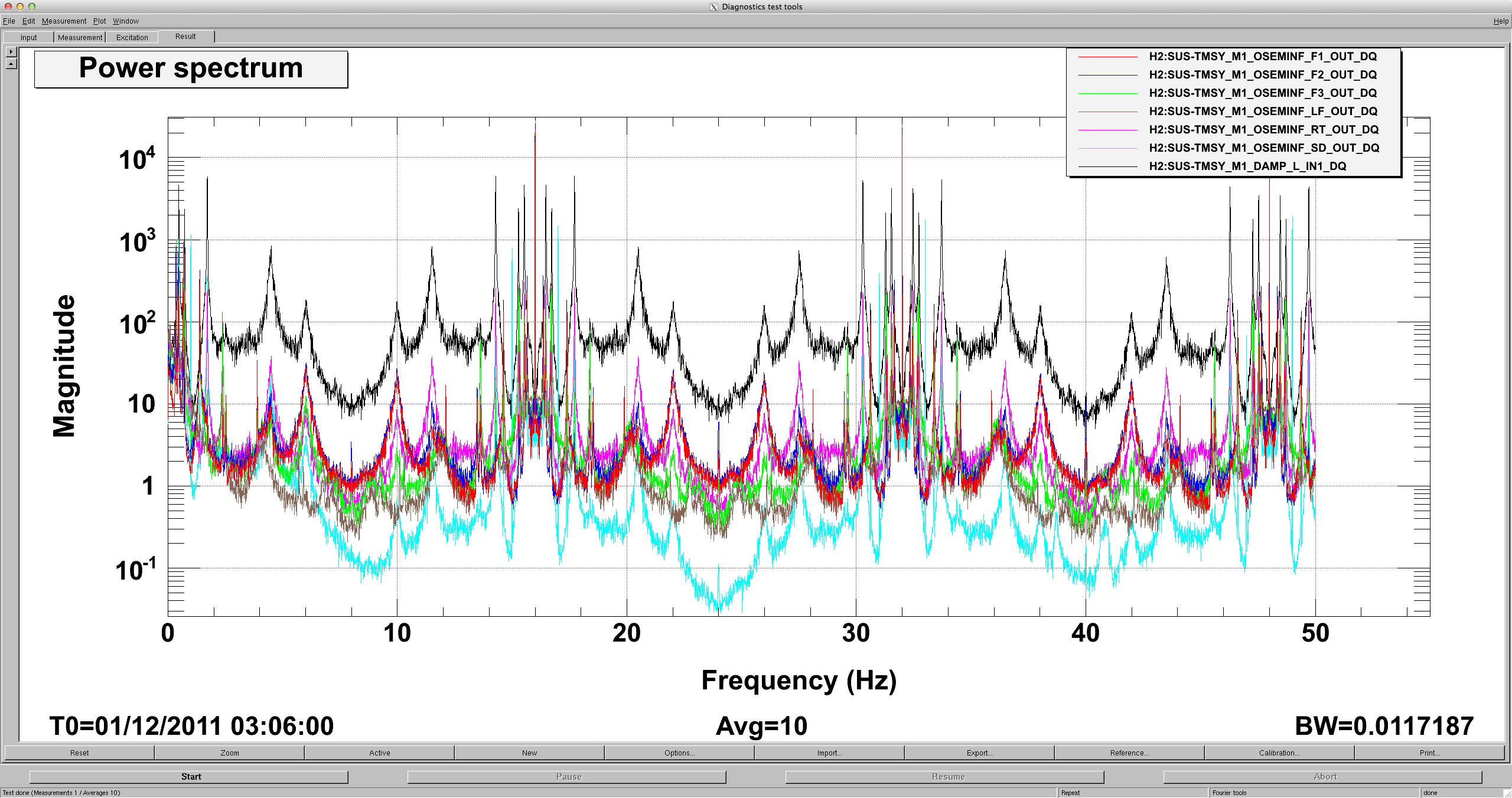
We made a few measurements of TMSY and got some damping loops running. The attached plots show:
We've left the damping loops on for a few days and they appear to be working well.
This morning, the SUS crew added the remaining mass to the H2 ITMY QUAD structure by adding the stiffening sleeve with vibration absorbers. The seismic crew has now balanced the ISI with the full ITMY and FMY structures. The BSC-ISI is now locked so that Romer arm measurements can begin on the ITMY QUAD and Test Mass. The afternoon's goal is to have the BSC-ISI floating with the H2 ITMY fully suspended and OSEM flags to center-range.
When you look back in time using DQ channels, everything is infested by pesky 16 Hz and its harmonics, also 1Hz line for some of the signals. This was not the case when the measurement was done yesterday using live data.
It might be that the problem SUS people had and solved by a code upgrade is attacking us.
Attached are power trends for the eLIGO H1 PSL since the replacement of the pump diodes and NPRO, in early July 2010. Due to Dataviewer issues, I could not create a single plot for the channels, and instead pasted together 3 month increments of data. These plots show the power of the pump diodes and NPRO diodes, the pump diode current, and power at the amplification stages. Note that the amplification power is not calibrated properly and is relative to the other amplifcation stages.
Tuesday the ISI table level was checked and found to be within 0.2mm, and on Wednesday we performed initial yaw measurements (yaw measured at 2.61 mrad).
Yesterday we measured the ITM yaw and horizontal position. The yaw was confirmed to be 2.6 mrad out of alignment (initial measurement done Wednesday) but the horizontal position was found to be 0.46mm from center, which is well within the ±1mm spec.
As Betsy stated in her alog we were able to correct the ITM yaw to ~400 µrad (the spec for rough yaw alignment is ±1mrad). After this we used the Microscribe to measure the gap between the corner cube retroreflector (used for y-axis distance measurement) and the ITM so we could get an accurate meaurement of the y-axis (longitudinal) position of the ITM. This gap was measured at 52.6mm and the total station measured 6982mm to the corner cube, resulting in a total distance from the total station to the ITM of 7034.6mm; the desired distance in 7041.3mm, so this shows the ITM structure to be to far forward on the ISI by 6.7mm. We are currently looking for the source of this error. Since the structure was moved in yaw, we also need to recheck the horizontal position of the ITM to ensure it is still within spec; these 3 degrees of freedom (yaw, horizontal position, and longitudinal position) need to be checked every time the structure is moved.
We are currently looking for the source of the FM longitudinal error as well.
Today, Jeff and Andres put the ETMy lower structure into the test stand clean room, and separated the chains, in prep for it's remodel for the monolithic. They unloaded the Dummy TM, Dummy PUM and wire segments and parked it in the adjascent fiber welding clean room. The ring heater crew will commence their addition to this structure tomorrow. I anticipate loading it with glass early next week.
This morning, IAS reverified that we needed to yaw the ITMy tower a few mRAD. We clamped both chains and took a baseline reading of the ITMy pointing in the clamped state. We then loosened the dog clamps holding the structure to the ISI table and took another reading. The dog clamps were still somewhat tight on the tower, no gap between the structure and table was noticeable. Jason will post the numbers in a subsequent entry. Using the new Pushers/Movers we were able to push opposite corners of the structure to reduce the yaw to ~20uRAD. We then tighted some of the dog clamps and observed that the yaw had walked out to ~400uRAD. We paused there and took the Y-axis reading. Unfortunately the structure appears to be out of position on the table in this direction by ~6mm. The initial placement of the structure nor the error in how the mass is suspended inside the structure account for this large misplacement. Dennis and Doug used the microscribe to measure the distance between the corner cube and the ITMy and also started looking into the optomechanical model in hopes to pinpoint where this 6mm error comes from. Meanwhile, they were going to continue with the foray of IAS measurements on the FMy. Fleshing out the next few days of interwoven IAS, Testing, and cartridge prep activities, but things look tight. We could not figure out a more efficient plan than the following: 1) determine how far ITMy and FMy structures need to be pushed around on ISI table (this afternoon-tomorrow morning) 2) push structures in x,y as needed, adjusting yaw as needed (tomorrow) 3) attach sleeve, vibrationabsorber payloads, continue fine IAS alignment to finalise yaw and pitch (Sunday) 4) SEI rebalance table payload, but leave locked until COB (Monday morning) 5) IAS measure ITMy to CP gap, SUS to adjust if needed Monday afternoon) 6) unlock ISI for TESTING (Monday night) 7) TEST (Monday night? - few days) 8) during testing gaps, prep suses for cartridge install (Monday-Wed)
After discussions this morning, we will rearrange the order of events spelled out in my a log last nigh. It seems that the 6mm y-direction discrepancy was not a quick find yesterday and will take longer to find it's source. So, IAS needs an hour this morning to make some measurements and then we'll move to adding sleeve/vibration absorber payload. This afternoon SEI will float and rebalance, so testing can start this weekend. We should be prepared to make structure coarse corrections next week.
Yesterday, seismic restarted testing HAM-ISI in the staging building. It seems that one of the horizontal GS13 is malfunctioning. The symptoms are similar to those we see when the proof mass is stuck (no low frequency response but high frequency response looks OK). After hitting the GS13 with a wrench and handling it, the mass is still stuck. I have attached Powerspectra of the 3 horizontal geophones when the ISI is locked (H3 geophone is the bad one).
The horizontal GS-13 POD SN 68 was opened and inspected. The flexure rods were not broken and the proof mass was moving freely when the geophone was leveled. One kinematic foot or the crossbar was probably not tightened down allowing the geophone to tilt inside the leveled can. Consequently the mass proof was touching the stops.
Kinematic feet of the horizontal GS13POD SN 68 were readjusted and the crossbar tightened up. After adding the can and reinstalling the GS13 in the HAM-ISI, a powerspectrum (attachment) confirmed that the geophone is functioning properly.