- Spool installed at MX - Clean room removed from BSC7 - Welding at EY - DougC and JasonO surveying in the LVEA, out by 1600 0900 - Oracle arrives for GregM and DanM to install new tape library 0930 - Locksmith arrives for Ski 1400 - Gil Hibbs arrives to inspect roofs of buildings with RichardM 1625 - LVEA in Laser Hazard
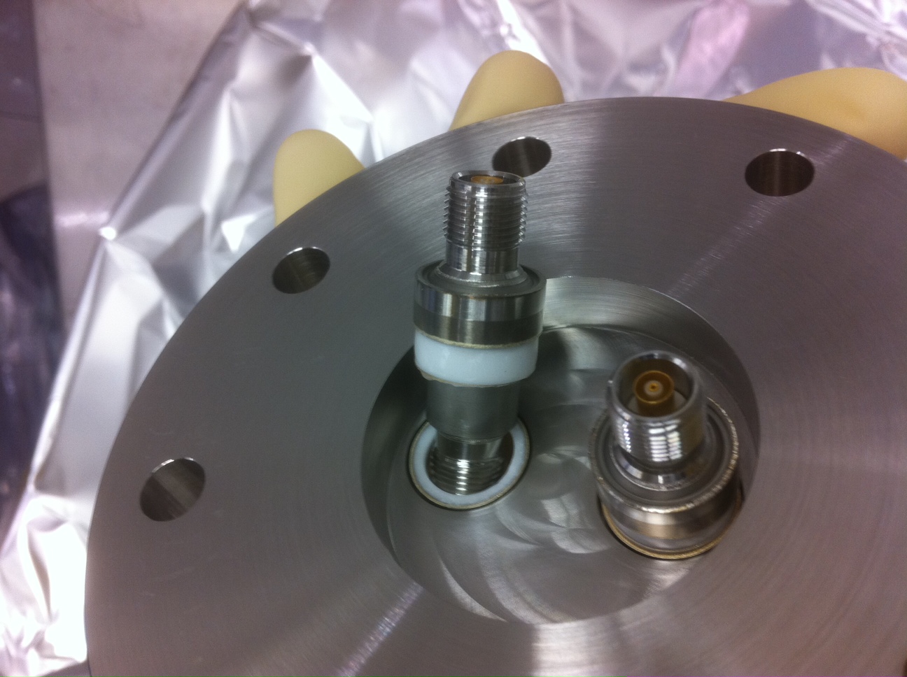
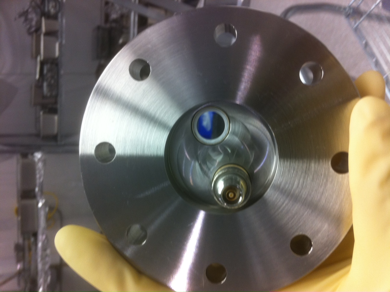
For the ISI System, our Capacitive Position Sensors have in-vacuum cables which require a certain type of feedthru flange to exit the vacuum system: Triax Connector Feedthru Flange.
We recently had some of these flanges Class-A-ed, and wanted to use some of these down in the Staging Bldg. One of these flanges was inspected and left on a table. During clean-up, I moved it from the table on to one of our racks. Yesterday, when pulling this part from the rack, I discovered that the flange was damaged beyond vacuum functionality. In a nut shell, one (of 2) connectors was broken off the flange. The connector is attached to the steel flange via a ceramic material, and this was the source of the vacuum failure for these flanges: 1 (of the 2) connectors must have been pushed enough to crack. [see photos]
This is a bit scary, so we will want to exercise extreme care with these flanges/connectors/cables. Is there strain-relief for the cables (could easily envision someone stepping on an in-air cable on the floor and potentially pulling against this delicate connector enough to cause the plug to fail mechanically fail. We should also be careful handling these flanges through all steps of their life (i.e. don't cram them together when they are bagged after clean & bake, don't store them in areas where they can be easily bumped, etc.)
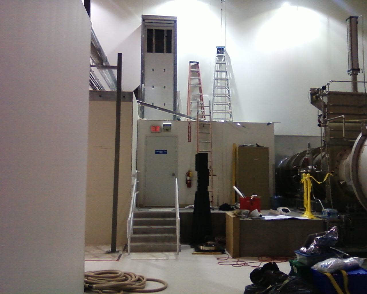
Many have been curious regarding the nature of the H2 PSL Diode Room work today involving cascading ladders, which is invisible from the H2 camera behind the crane rail. Attached is a photo indicating what seems to be ductwork penetrating the northern wall of the LVEA from a view that is impossible from within the Control Room.
#### - Author - Task --------------------- 2883 - Apollo - Install new spool section instead of BSC5 2882 - Apollo - Move clean room from BSC7 to allow for optical surveying 2879 - DougC - Place IAS brass monuments in the LVEA... 2878 - Jodi/Apollo - ICC at BSC8 2877 - Apollo - Move cleanrooms in preparation for ICC in BSC8 2876 - Hugh - Run HEPI plumbing from pump stations to BSC6 2875 - Apollo/Hugh - Rebuild SEI External Hardware at EY... 2874 - Hugh - Install HEPI HAM7 Mechanical Hardware 2873 - GregM - Remove L700 tape library... 2865 - MichaelR - Construction of H2-PSL Diode and Chiller Room 2860 - Apollo - Relocate BSC5 from MX to EX 2846 - Apollo - Install new duct and repair existing duct for oven exhaust 2845 - Apollo - Excavate for line sets and install cooling units for H2 electronics building 2831 - GregorioT - Characterizing OpLev lasers 2828 - GregorioT/RickS - OpLev pier assembly, testing at MY 2816 - Jodi/Apollo - ICC at BSC7 2796 - Dani - Daily Laser Hazard/Laser Safe Transitions 2691 - EricA - Pump HEPI fluid from ground to Mezzanine and start pumps Please close out your work permit upon completion of the task.
Took TFs again for both M0 and R0 chains after yesterdays adjustments (see Report for more info). M0 still looks good (matches well to the approved baseline released several days ago). R0 still needs work. The entire Transverse is, well gross. The third Pitch mode is marginally better, but nowhere near where it needs to be. I also observed large amounts of coupling from Vertical to Yaw (extra plot attached), greater in magnitude than Vertical, at the second Vertical mode.
R. Lane, A. Ramirez on July 7, 2011 Took passive TFs from Top M0 Right to Top M0 Left, rotating each other OSEM through Top M0 Left while leaving Top M0 Right in place. These measurements were to "calibrate" the OSEMs relative to themselves and hopefully remove any variance between them. Results below show the same rough shape, but do vary slightly in magnitude.
Betsy, Travis, Rob There appeared to still be some mismatch of one of the peaks in the reaction chain transfer functions, which was believed to be from a blade tip at the wrong height. Today, I found that indeed both top mass blades were on the order of 1mm out - 1 up, 1 down. After a rigorous round of readjusting those which involved removing the top of the table cloth and BOSEMs, I induced a pitch. Another round of tip adjustment ensued, followed by coarse pitch adjustment via the mechanics on the underside of the top mass. Once hanging normal again, I found that the side BOSEM would not mate to the mass flag which was now hanging quite low. To fix this, I had to reset the table cloth position in the upper structure to lower the BOSEM mating location to match the position of the mass flag. After another round of diagonalization of both R0 and M0 BOSEMs, Rob is back to taking TFs. There is still a bit of differential roll observed by eye between the R0 UIM and Top Mass, but we'll see what the data looks like. I hope these will reveal a healthy R0 such that I can get on with lacing the lower cables by the end of the week.
Greg G., Hobo S.
HAM 7 now has the HEPI housings and crossbeams installed. Final positioning still needs to take place. I tried a different method of attaching the crossbeams; clamping them to the housings before fully setting the weight of the crossbeam onto the support tubes. When they are sighted in we'll see if this made a difference. Doing so seems to help keep the feet inside the housings more level.
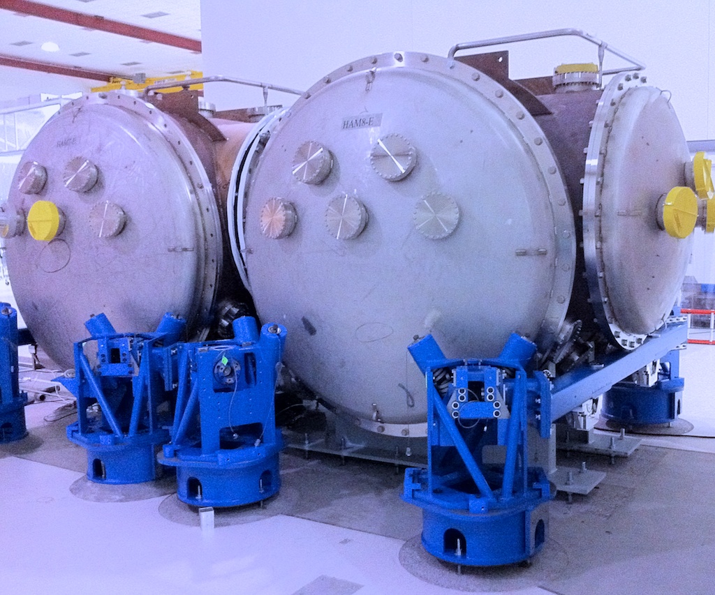
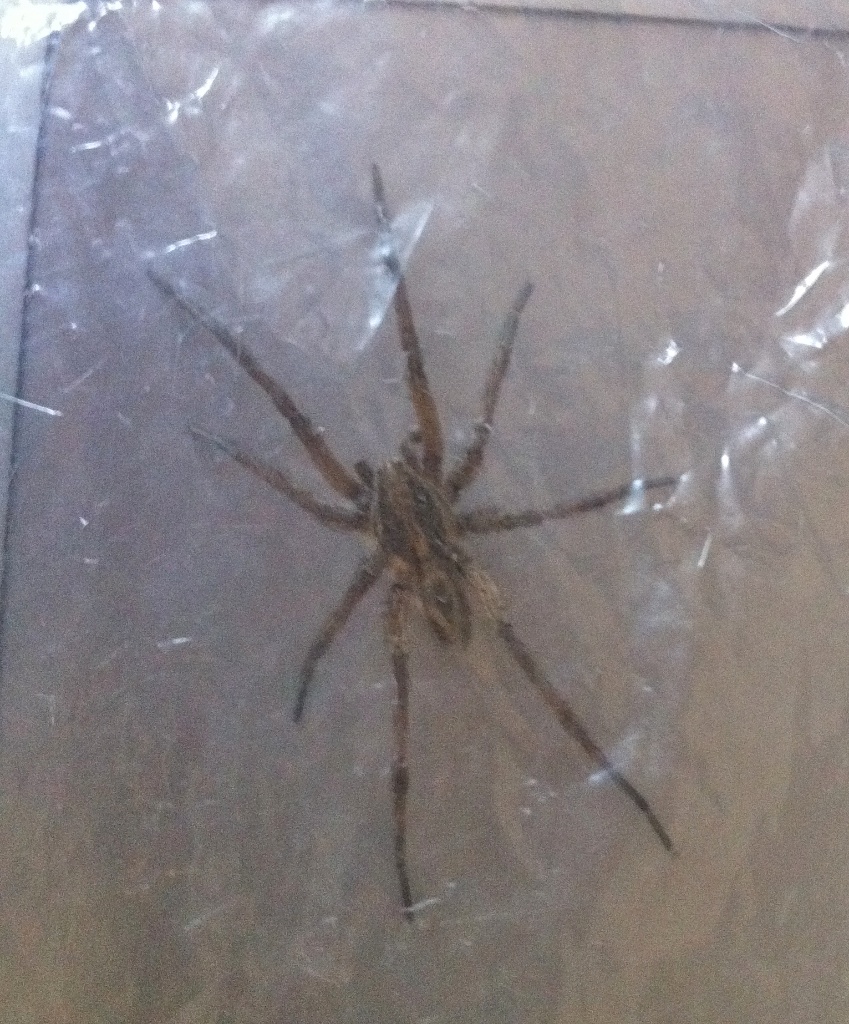
Space was very limited in between HAMs 7 & 8 which led to me having to crawl under the chamber to reach all of the bolts. While there I encountered a friend (picture attached), however, we were in laser hazard and lacking proper safety glasses he had to be escorted out of the LVEA.
Work in LVEA for the PSL chiller room Work down at Mid-X and End-X for the preparation and move of the BSC 5 chamber to End-X Gregorio out to Mid-X SUS and SEI commissioners out in the LVEA at various times.
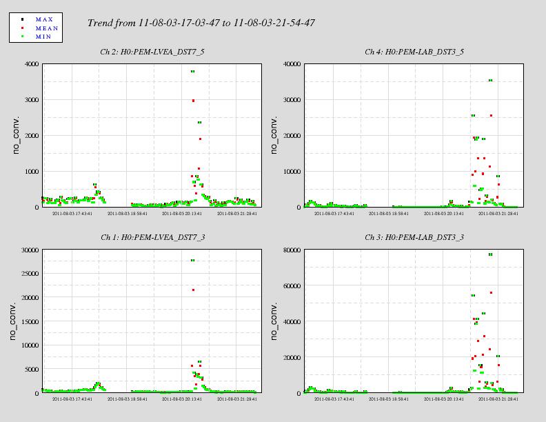
Dust levels spiked in the LVEA North Bay just after lunchtime on dust monitor 7 (H0:PEM-LVEA_DST7_3 and H0:PEM-LVEA_DST7_5). The levels spiked up to over 22,000cts from a nominal ~100-300cts. The Bake Room monitor spiked as well at a later time from the LVEA spike. Plots attached.
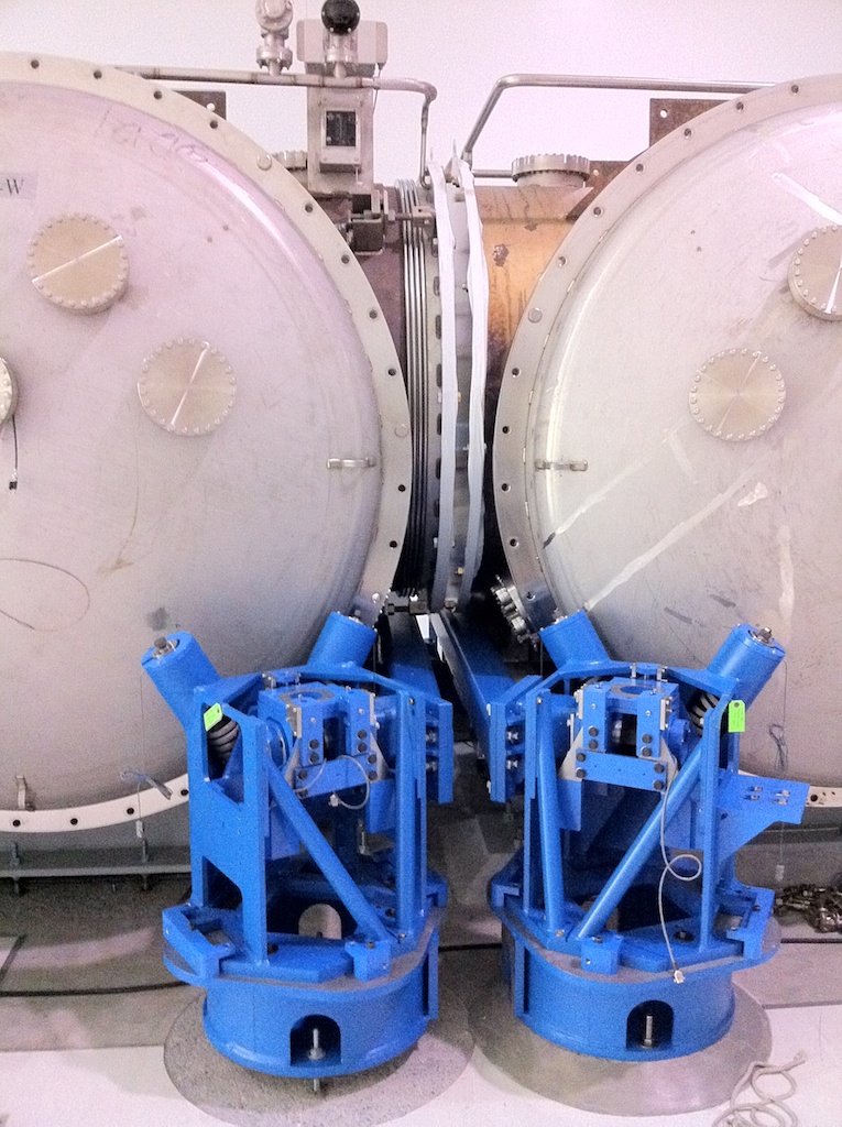
The BSC from the X-arm mid-station was successfully moved to the end station. The operation went very smoothly and efficiently: this move took about half the time of the Y-arm move. Photos will be loaded to Resource Space.
E. Effler, R. Lane, J . Kissel, B. Shapiro After Anamaria successfully completed transfer functions at LLO of QUAD11, and Robert was able to complete transfer functions of H2SUSITMY (QUAD02), I've collected all the data* we have on the assembled and tested QUADs (@ LHO, QUAD03, H2SUSITMY; @LLO QUAD11, 12, 13, and 14), onto a single set of plots. From these results, we can conclude that H2SUSITMY's reaction chain has it's second pitch mode too low, compared with all other QUADs. This mode is particularly sensitive to the d's (distance between suspension break-off point and center of mass for a given stage) of the TOP / UIM stage (either dn or d1, see T1000458, QUADModelParamsDiagram_T1000458-v6.pdf), to which the only adjustable physical parameter this corresponds are the TOP and UIM blade tip heights. The guess (from discussions with Brett) is that with such a large deviation in the Pitch mode, that such a discrepancy in blade tip heights should be visible with the standard gauge block measure of the heights. *Note that I've not included QUAD01, who's measurements were bad because of measurement error, and also, a few of the degrees of freedom on QUAD03 show low magnitude -- this is also measurement error (not driving hard enough), we believe the dynamics are OK.
(Corey, Jeff, Jim)
Overall Assembly Tweaks
Trillium Doors were installed, bolt-on weights were installed, and then the system was checked for balance. Jim noticed a slight rotation from lock/unlock state and adjusted Lockers accordingly.
In-Vaccum Cabling
In-vacuum cabling was run to the mock-feedthru for the Trilliums, L4Cs, GS13s, and Actuators.
For the Actuators, their cables were rung out to determine which wire (actuator-side) is the "center" wire on the feedthru-connector-side. We then connected wires to Actuators in consistent manner on the Actuators (hopefully it was the right way sign-wise...we'll see when we can start actuating).
The Capacitive Position Sensors (CPS) were not run to the mock-feedthru because we are missing their triax connectors (should be receiving later this week); in meantime, we will use actual flange-feedthrus.
Class-B name tags were attached to in-vacuum cables (on the ends connecting to the mock-feedthru).
Test Stand & In-Air Cabling
The Test Stand, as it was positioned, had cables which couldn't reach Assembly#2, so the rack was powered down, and rolled a few feet West.
The In-Air cabling was then sorted and bundled for connection to the dirty-side of the mock feedthru.
The crew spent the morning moving a cleanroom out of the laser enclosure (It will be used as a clean area for assembling air drills.), straightening up the bay by HAM-1, and moving small chamber cleaning paraphernalia from BSC-7 to the BSC-8 area. Once Kyle got a chance to remove the pump by BSC-8 and hard close GV-5, several loads of chamber cleaning equipment and two 7'x 10' cleanrooms were flown over the beam tube. Doug and I agreed on a plan forward for the working in the LVEA for the remainder of the week. (I posted it to the alog earlier if anyone is interested.) FTIR results for the BSC-7 chamber body arrived from JPL this afternoon and were forwarded to the Chamber Cleaning group for analysis and comment.
The alarm is going enough right now to indicate a low temperature value, but the trend shows normal-looking behavior.
Kyle, Gerardo
Recent attempts at sealing the ceiling tiles and damp mopping/wiping the floors and walls etc. have had virtually no impact on the particulate monitoring counts in room 169 (OSB bake-oven room) -> Recalling that the particulate count increase roughly coincided in time with the decision to keep the door closed between the bake-oven room and the adjacent vacuum prep lab., I decided to prop open the door and leave it open overnight. The result was a return to traditional particle counts in both rooms, i.e., a major improvement in the bake-oven room and no change (or a slight improvement) in the vacuum prep. lab -> I'm leaving this door open until overruled by a higher power
- FredR in place of MikeL for INS coordination today - Reibold on site, cautioned against bringing in Mountain Dew and paper towels to LVEA (contamination concerns) - Laser Hazard all day today for squeezer work (compromise with Doug Cook and IAS in exchange for no laser hazard Wed. - Fri.) - Jodi staging in HAM1/South Bay area for BSC8 ICC - GregG working around HAM7 - Braising at EY - Test stand assembly at EY 0900 - Diamond Frieght shipment for TerryS and BetsyB 0910 - Scrap wood bin replacement 0931 - UniFirst arrives 1108 - Septic Tank trunk arrives 1126 - Walter and Gregorio to MY 1200 - Praxair begins filling wrong tank by LVEA, Kyle fixes situation 1330 - RichardM and CyrusR move H2 Y-arm racks to accommodate monument surveying. Dust alarm by ISI stand as GerardoM and KyleR were working in the area 1332 - Kyle begins closing GV5 1500 - Gown room placed near BSC8
Co-ordination Planning for LVEA
02-05 August 2011
Tuesday, 02 Aug 2011-Laser Hazard
Kyle to remove pump cart from near BSC-8 and hard-close GV-5
Richard / Apollo to slide the ISI racks forward to accommodate survey crew on Y-arm
ICC to stage all possible items to the PSL-1 area, including 2 garbing/staging cleanrooms
Wednesday, 03 Aug 2011-Laser Safe-Crane work restricted during shots
Doug and crew to take required shots along Y-arm
Kyle to vent volume needed for BSC-8 entry?
Thursday, 04 Aug 2011-Laser Safe-Crane work restricted during shots
ICC to move large cleanroom over BSC-8 chamber (as long as shots are finished)
ICC to remove cleanroom from BSC-7 and set it down out of the sight lines for new H2 shots (Dome cleanroom)
Doug and crew to take required shots along X-arm
Friday, 05 Aug 2011-Laser Safe-Crane work restricted during shots
ICC to move dome cleanroom into place near HAM 11-12 (as long as shots are finished)
Doug and crew to complete survey work
We tested a clean method of power cycling a front end. First all user models were killed, followed by the iop. At this point the only things running were the awgtpman process which were restarted by monit. We then IPMI power cycled the frontend (h2susauxb478) and did not affect the daq status of the other running front ends.
I'll write this up as the reboot procedure for frontends in the wiki.
We then simulated a loss of the h2boot server by disconnecting it from the H2FE LAN. The front end medm screens froze up, but did not go "white screen". All medms just froze in a "good" state. The control room workstation of course slowed because they tried to mount /opt/rtcds, and no new medms could be opened because of the file server loss. When h2boot was re-attached to the LAN everything came back alive. Vincent looked at an ISI fast channel and verifed the front end was running and sending data to the DAQ for the whole time.