jodi.fauver@LIGO.ORG - posted 16:39, Tuesday 21 December 2010 (433)
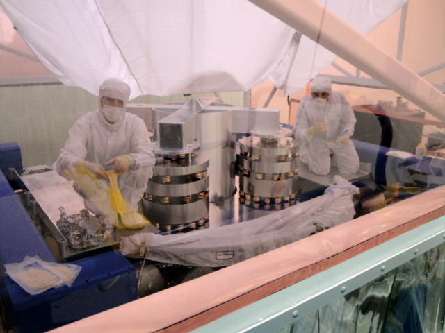
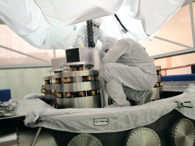
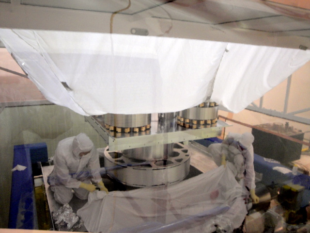
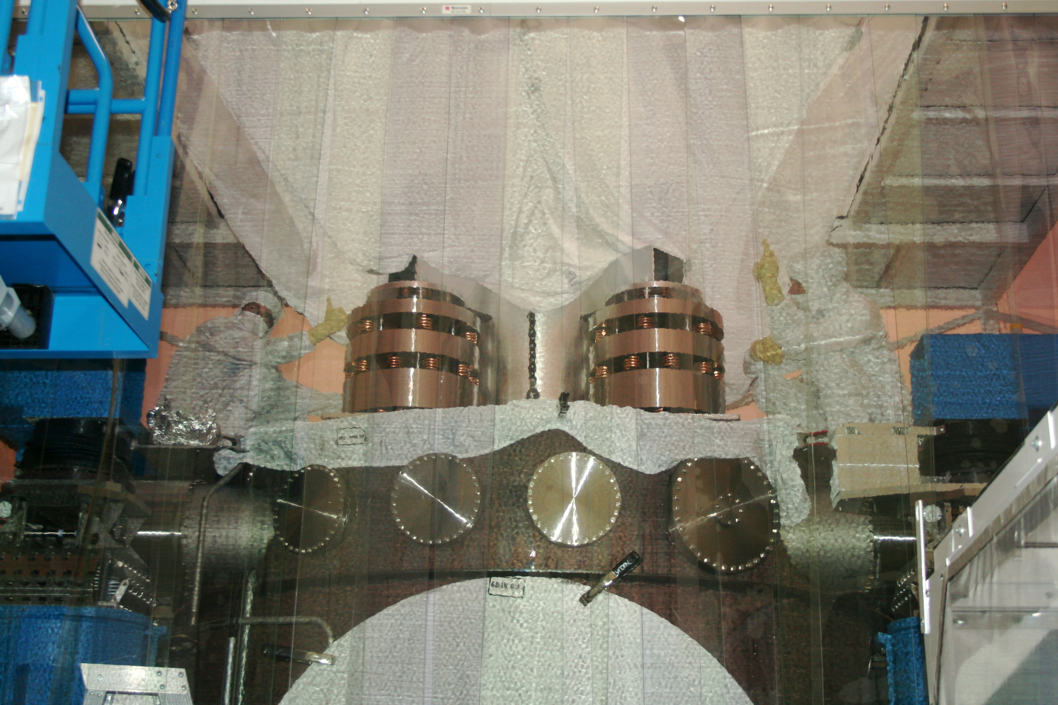
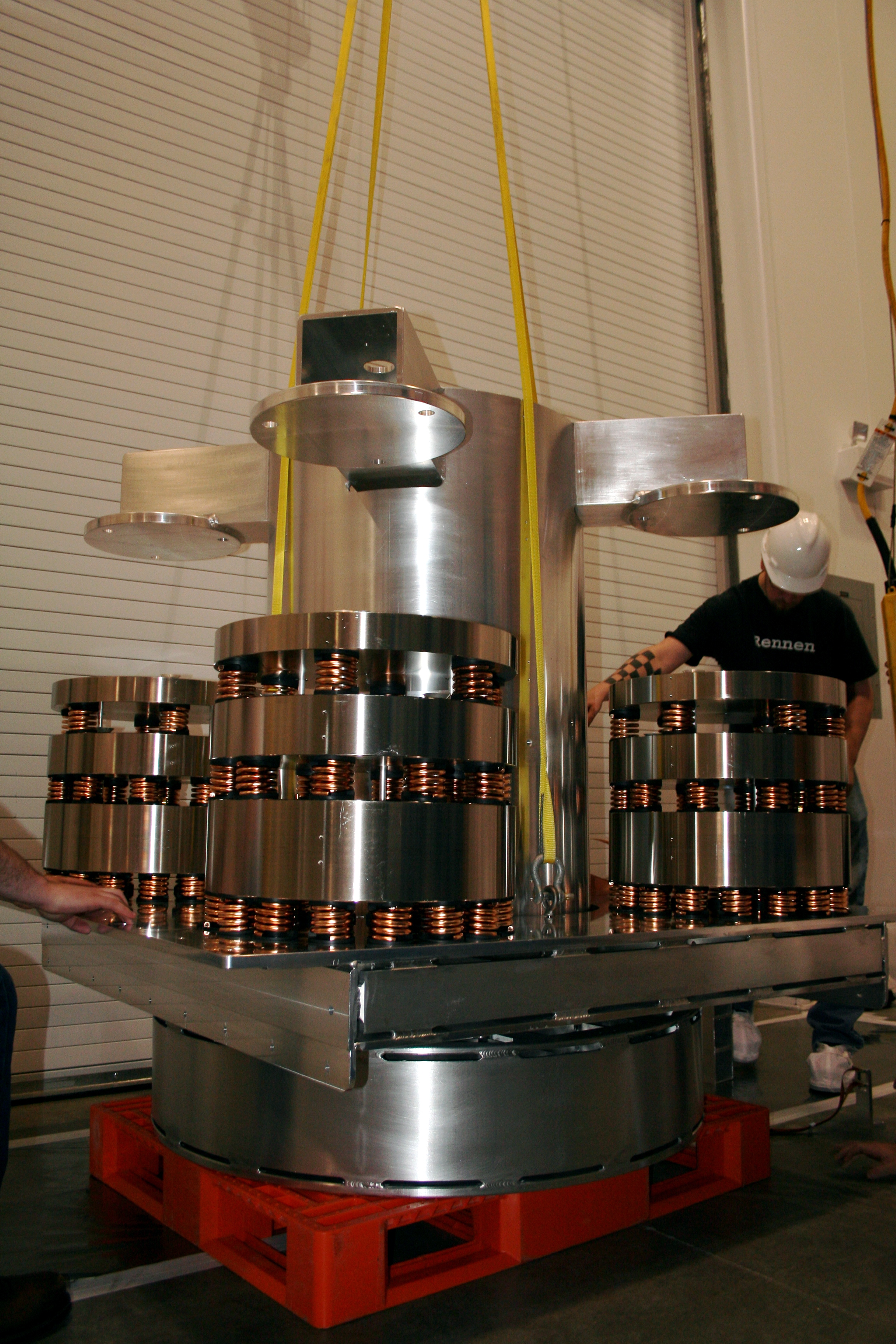
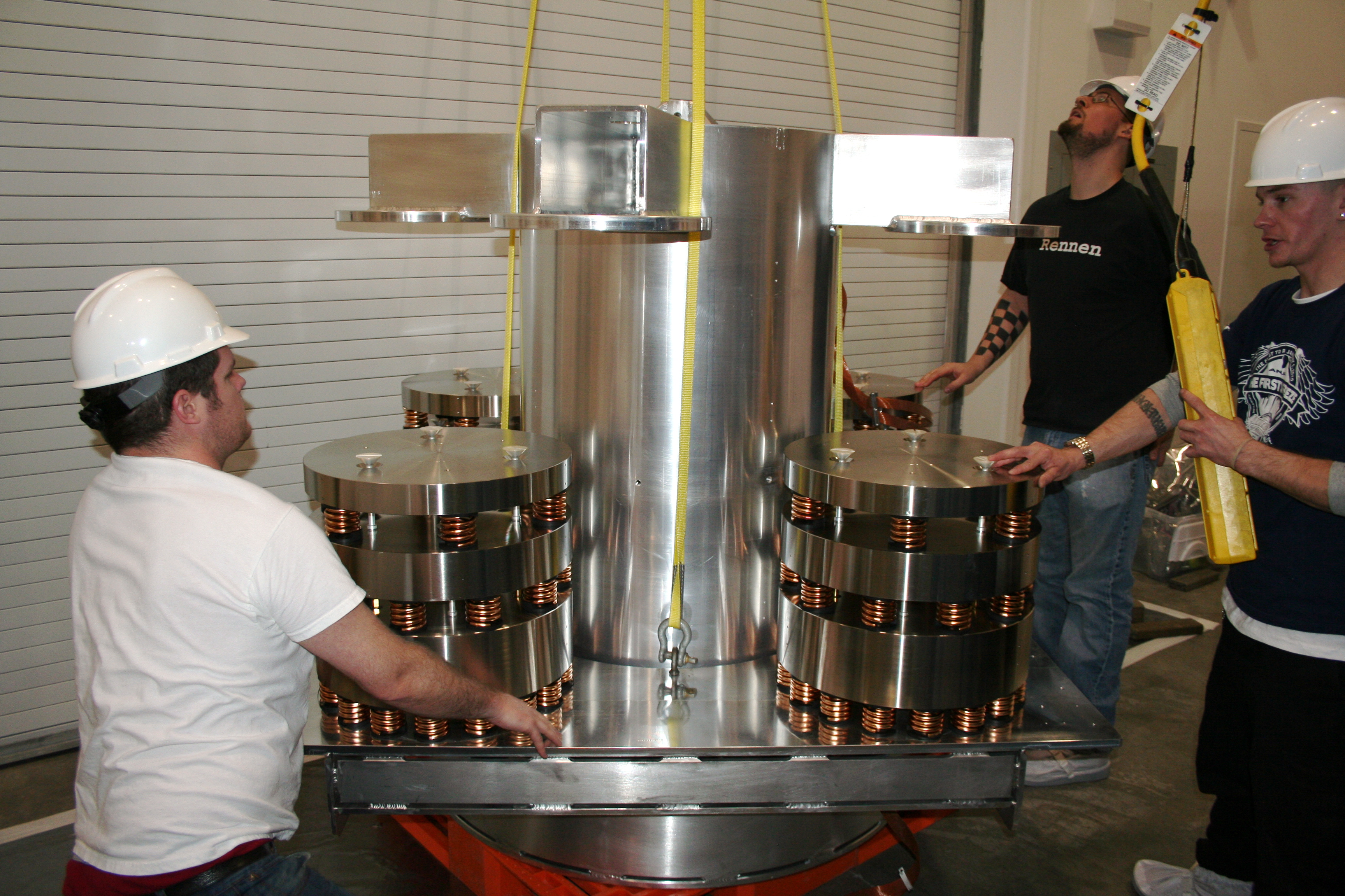
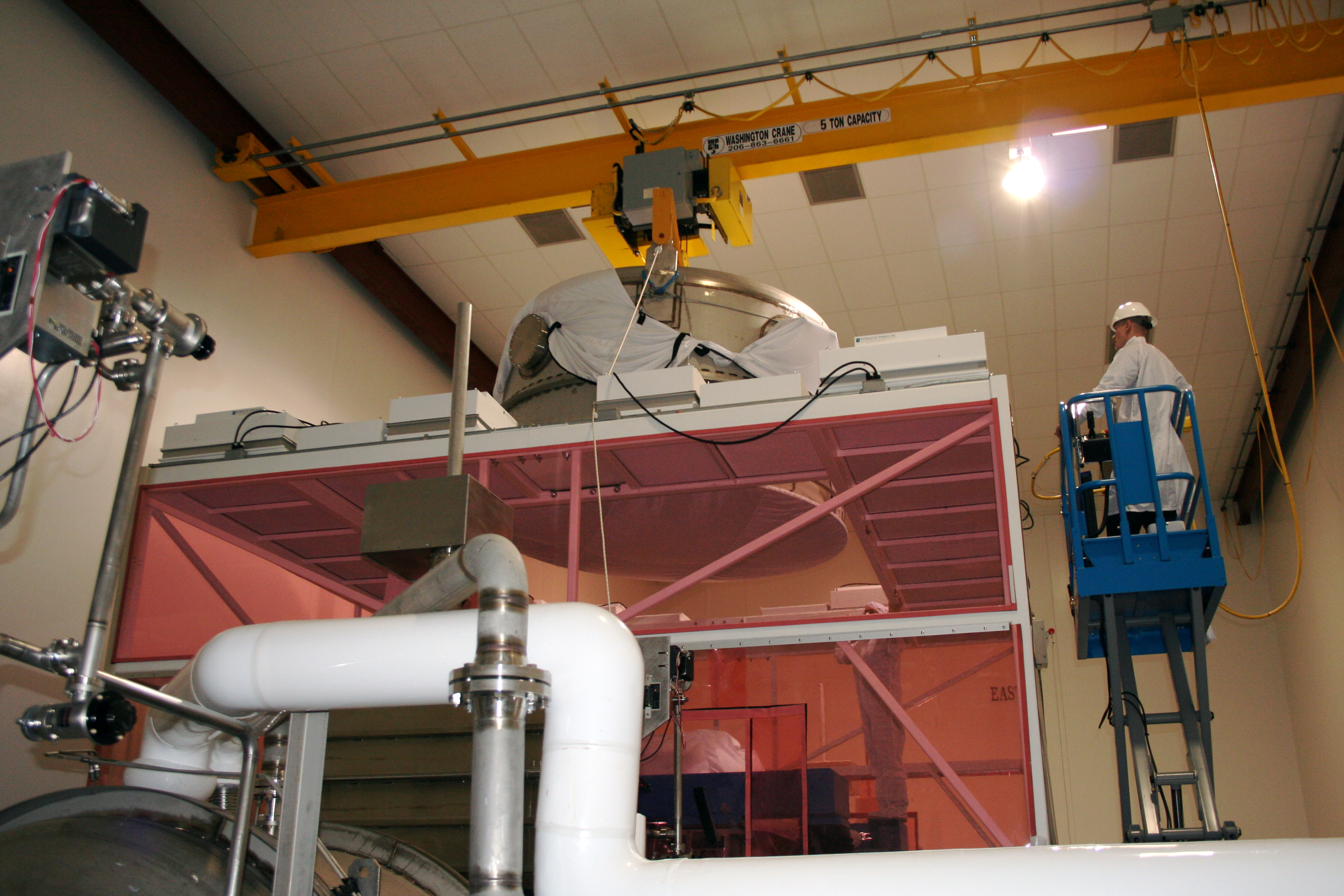
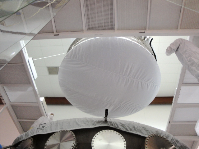
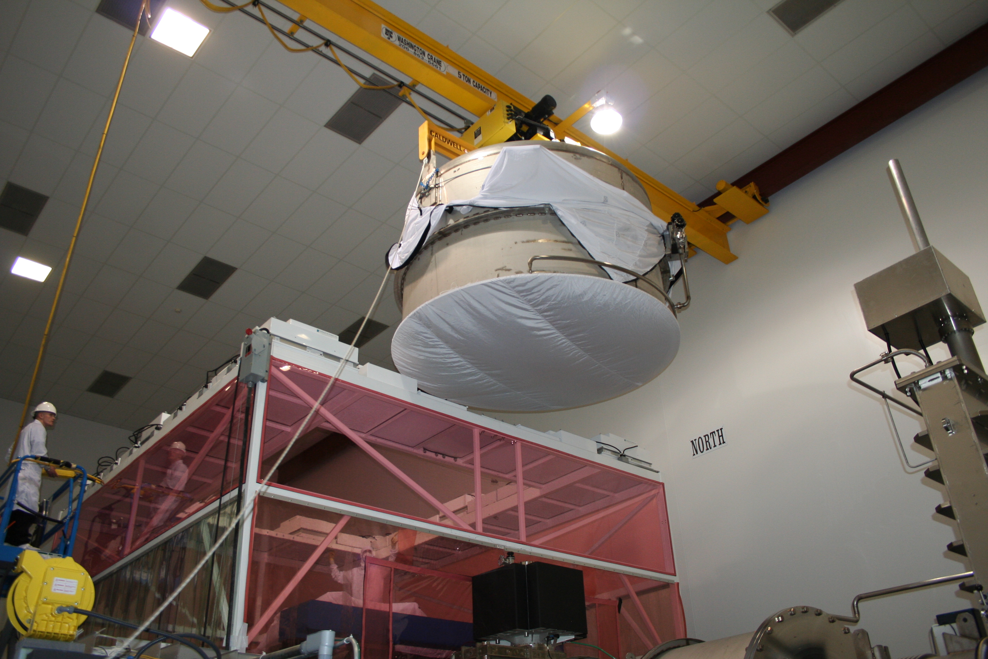
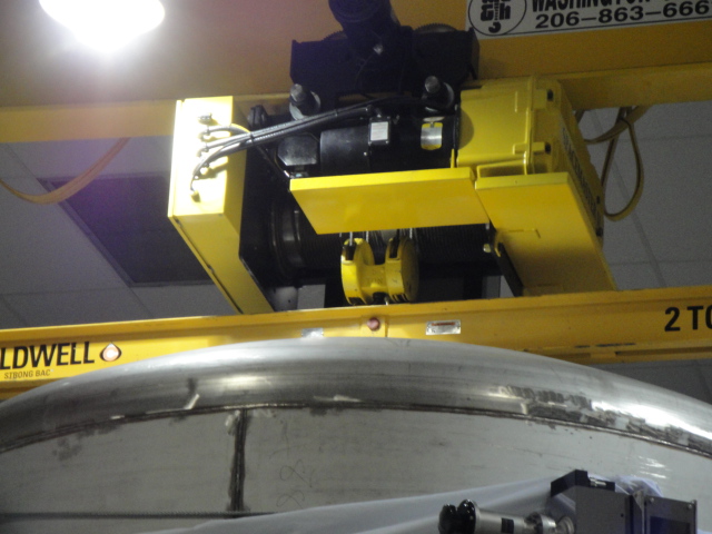
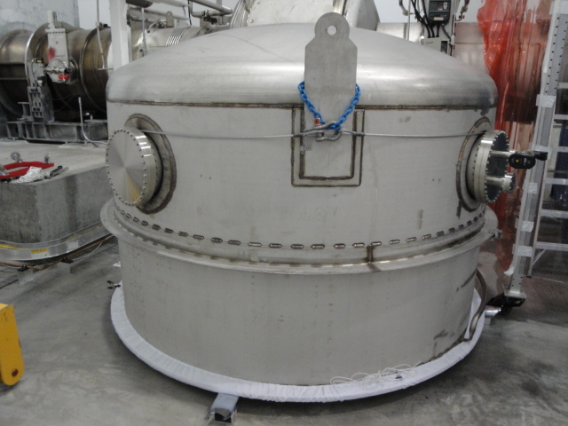
HAM 12 Chamber Cleaning Test-Take 2
We went into HAM 12 today for the purpose of trying out the modifications to the rotary tool and funnel for collecting freon samples. (We were also hoping to take some more "legitimate" freon samples today but sample bottles did not arrive.)

Report on rotary tool:
1. Housing modifications (housing was split down the middle) worked well: the housing was easy to take apart/put together and speed could be changed without dis-assembly.
2. Stem (replaced the chuck) worked very well.
3. Fabric sock needs work: still did not allow enough "play".
4. Vertical brushing does not seem to generate as much particulate as horizontal brushing.
5. Cup brush lost a bristle today.
6. Current bush does not allow tool to be used to clean close to "fins".

Report on funnel:
1. Horizontal orientation seems easier to use.
2. Radius of curvature on the rear wall of the funnel allowed closer contact with chamber wall.
3. Handle allowed pressure to be applied to increase contact between chamber and funnel wall.
4. Thinner metal seemed to make a difference as well.
5. We collected ~80% of the freon that we poured in the trial run.
6. We are likely to add a valve to allow collection in chamber but recovery in the staging area.

Misc.
1. We tried brushing near a "fin" with a stainless toothbrush which cleaned the chamber wall effectively but generated high particle counts.
2. We ran the external purge air unit with the output ducted to a HEPA filter.

I will post some official report on the DCC that includes pix.
