Displaying reports 901-920 of 88435.Go to page Start 42 43 44 45 46 47 48 49 50 End
Reports until 21:15, Monday 04 May 2026
H1 CDS
david.barker@LIGO.ORG - posted 21:15, Monday 04 May 2026 - last comment - 08:49, Tuesday 05 May 2026(90116)
CP1 Regen Alarms

Gerardo, Jordan, Jonathan, Dave:

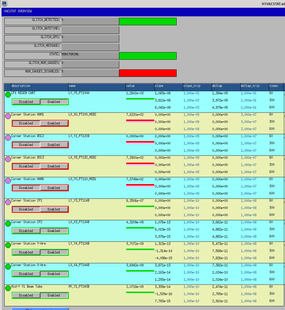
PT114 has started to rise rapidly. At 16:50 I changed its alarm high from 2.0e-08 to 5.0e-04.

Later PT114B's VACSTAT continued to trip due to the large delta-P. After clearing the alarms I have disabled PT114B in VACSTAT (but its level alarms remain active).

 

Images attached to this report
Comments related to this report
david.barker@LIGO.ORG - 21:28, Monday 04 May 2026 (90118)

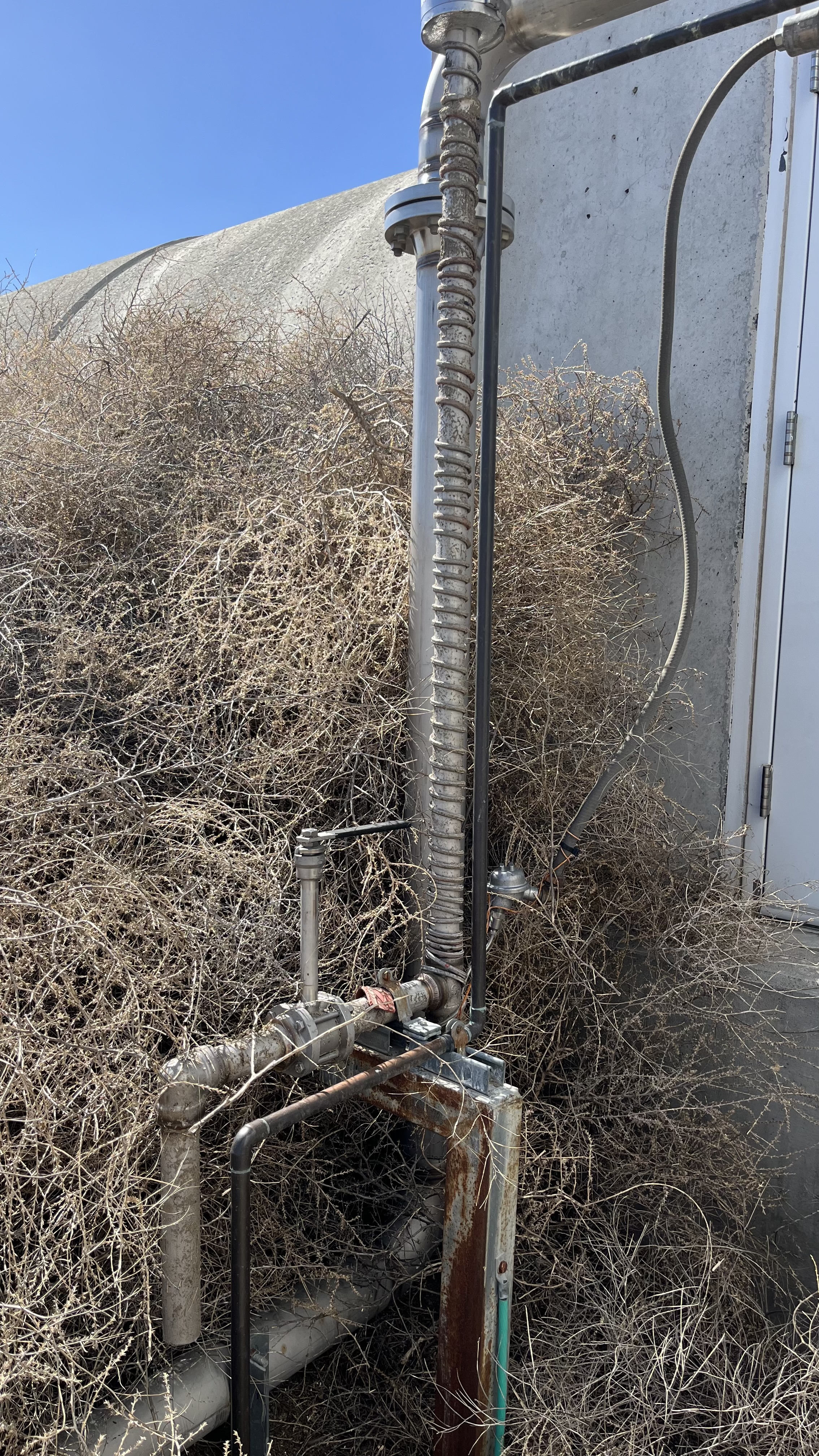
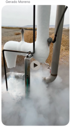
As mentioned by Gerardo CP1's outside discharge line pipe is now completely free of ice (Nov 2025 image added for comparison).

Images attached to this comment
ryan.short@LIGO.ORG - 08:49, Tuesday 05 May 2026 (90122)OpsInfo

The pressure at PT114 has continued to rise this morning and mostly leveled out, but it's bouncing around the channel's low-level alarm threshold at 1e-5 Torr. This is triggering Verbal Alarms and the CR alarm handler computer every time the pressure goes above 1e-5 Torr, which is on average a few times per minute.

I've commented out PT114 from the Verbal Alarms vacuum channel list to reduce redundant alarms and will look into modifying the thresholds somehow for the alarm handler.

Images attached to this comment
H1 CDS
david.barker@LIGO.ORG - posted 18:34, Monday 04 May 2026 - last comment - 21:10, Monday 04 May 2026(90113)
DAQ DC0 crash 18:35 Mon 04may2026

h1daqdc0 stopped running around the time I restarted vacstat_ioc on cdsioc0 to clear an alarm. DC0 is pingable, but we cannot ssh onto it. Jonathan is taking a look, we may have to power cycle it via IPMI.

Comments related to this report
david.barker@LIGO.ORG - 21:10, Monday 04 May 2026 (90115)

DC0 was power cycled at 18:52 PDT. After that we did a clean 0-leg restart to resync the other nodes to the DC.

H1 General
camilla.compton@LIGO.ORG - posted 17:12, Monday 04 May 2026 (90112)
ALS X Laser on

Turn ALS X laser back back on, we used it to take some ALS return beam beam profiles. It's been off since the interlock was worked on. It is now shuttered. 

H1 SUS (SUS)
ibrahim.abouelfettouh@LIGO.ORG - posted 17:06, Monday 04 May 2026 (90111)
BS/FM In-Vac Cables Replaced, Gold BS Baffles Removed, BBS Magnet Gluing Staged

Ibrahim, Betsy

Today we:

  1. Replaced the in-vac cables with the new QOSEM ones, maintaining their positions in the cable clamps
  2. Wrestled the gold BS baffles loose to make way for clearer alignment sighting
  3. Unpacked and set-up the magnet gluing set-up in prep for BBS01 arrival tomorrow.
H1 SPI (CDS)
jeffrey.kissel@LIGO.ORG - posted 16:11, Monday 04 May 2026 (90105)
SPI PD Calibration: 2026-05-04 Update
J. Kissel, T. Roocke

I was crossing the t's and dotting the i's on our documentation to better understand what calibration / compensation to install into the new SPI front-end / MEDM infrastructure. 

As such I was reconciling / validating the calibration info that Sina put in LHO:89739 (originally informed by derivations in E2600104) against the info Tom put in the three travelers 
    - S2500711 (Variant 1 for the HAM2 YAG444s), 
    - S2500712 (Variant 2 for the HAM3 4x FFD200s and one YAG444), and
    - S2500713 (Variant 3 for the HAM3 additional 2x FFD200s)

Two things were amiss:
(1) The values of resistors and capacitors were not consistent between Sina's "R4 Resistor value now (kohm)" and "C5 capacitor value now (pF)" columns, and what Tom stated in the traveler update. As such, I asked Tom to give me more detailed confirmation -- and he delivered excellently:
    S2500711 (Variant 1 for the HAM2 YAG444s)
    CH1-4 
        . R4 = 1.54kohm (P1.54KFCT-ND) 
        . C4 = 2.2nF (399-8171-1-ND)

    S2500712 (Variant 2 for the HAM3 4x FFD200s and one YAG444)
    CH1-2 
        . R4 = 4.99kohm (P4.99KFCT-ND) 
        . C4 = 560pF (PCC561BCT-ND)
    CH3-8 
        . R4 = 3.32kohm (P3.32KFCT-ND)
        . C4 = 1nF (PCC102BCT-ND)

    S2500713 (Variant 3 for the HAM3 additional 2x FFD200s)
    CH1-2 
        . R4 = 53.6kohm (P53.6KFCT-ND) 
        . C4 = 220pF (478-1484-1-ND)

(2) In our testing of the TIAs both *before* and *after* these component values were installed, we were comparing values measured power values with a Thorlabs S121C power meter (in [mW]) against the TIA ADC output voltage on the positive leg *only* (in [V]), after having verified that the negative leg consistently reported the negative of the positive leg on all channels. 

In E2600104-v1 the AA column for "PD Calibration" -- and thus Sina's "PD calibration (mW/V)" column in LHO:89739 is the ratio of the power and positive leg only, and thus missing a factor of 2.0.

So ... there's the updated table, with 
    - the transimpedance gain, "TIA gain" calculated as R4 * 2 [V_SE/V_DIFF], with the factor of two from the last ADC driver stage 
    - when engaged (rather than bypassed), the whitening stage with 
           z1 = 1 / ( 2*pi* (R1*C1 + R3*C2 + R3*C1) )
           z2 = (R1*C1 + R3*C2 + R3*C1) / ( 2*pi* (R1*C1*R3*C2) )
           p1 = 1 / ( 2*pi* (R1*C1) )
           p2 = 1 / ( 2*pi* (R3*C2))
    - FBR_PWRIN single-element PD Calibration at DC
            (power at PD) / ( 2 * (ADC volts pos leg) )
    - IFO single-element PD calibration at DC
            (SIG power + LO power) / ( 2 * (SIG ADC volts pos leg + LO ADC volts pos leg) )
    - QPD segment calibration
            percentage of voltage = ADC volts pos leg of each segment / (total pos leg voltage on all segments)
            (total power at QPD * percentage of voltage) / ( 2 * (ADC volts pos leg of each segment) ) 
    - a 16 bit ADC with 40 Vpp DIFFERENTIAL range, i.e. 40 / 2^16 = 6.1035e-4 [V/ct] or 2^16 / 40 = 1638.4 [ct/V] (see T1100538)


    DIGITAL NAME     ANALOG    R4        C4       TIA Gain   PD/SEG Calibration   TIA HF Pole    Whitening 
                     NAME      [kOhm]    [nF]     [V/A]      [mW/V]               [kHz]          (z1,z2:p1,p2) [Hz] 
QPDA
    OL_QPD_A_SEG1    CH1       1.54      2.20     3.08e3     2.0556               46.976         (0.394, 8.06e6: 39.8, 79.6e3)    
    OL_QPD_A_SEG2    CH2       1.54      2.20     3.08e3     2.0556               46.976         (0.394, 8.06e6: 39.8, 79.6e3)    
    OL_QPD_A_SEG3    CH3       1.54      2.20     3.08e3     2.0556               46.976         (0.394, 8.06e6: 39.8, 79.6e3)    
    OL_QPD_A_SEG4    CH4       1.54      2.20     3.08e3     2.0556               46.976         (0.394, 8.06e6: 39.8, 79.6e3)    


IFO
    IFO_MEAS_A       CH1       4.99      0.56     9.98e3     1.0959               56.955         bypassed
    IFO_MEAS_B       CH2       4.99      0.56     9.98e3     1.0619               56.955         bypassed
    IFO_REF_A        CH3       3.32      1.00     6.64e3     0.6042               47.938         bypassed
    IFO_REF_B        CH4       3.32      1.00     6.64e3     0.6304               47.938         bypassed   

QPDB
    OL_QPD_B_SEG1    CH5       3.32      1.00     6.64e3     0.3667               47.938         (0.394, 8.06e6: 39.8, 79.6e3)  
    OL_QPD_B_SEG2    CH6       3.32      1.00     6.64e3     0.3667               47.938         (0.394, 8.06e6: 39.8, 79.6e3)
    OL_QPD_B_SEG3    CH7       3.32      1.00     6.64e3     0.3667               47.938         (0.394, 8.06e6: 39.8, 79.6e3)
    OL_QPD_B_SEG4    CH8       3.32      1.00     6.64e3     0.3667               47.938         (0.394, 8.06e6: 39.8, 79.6e3)

POWER
    FBR_PWRIN_MEAS   CH1      53.60      0.22   107.2e3      0.1154               13.497         bypassed 
    FBR_PWRIN_REF    CH2      53.60      0.22   107.2e3      0.1176               13.497         bypassed 


I've updated E2600104 (the google sheet), exported it and uploaded that to -v2 to corroborate.
H1 PSL
ryan.short@LIGO.ORG - posted 10:10, Monday 04 May 2026 (90102)
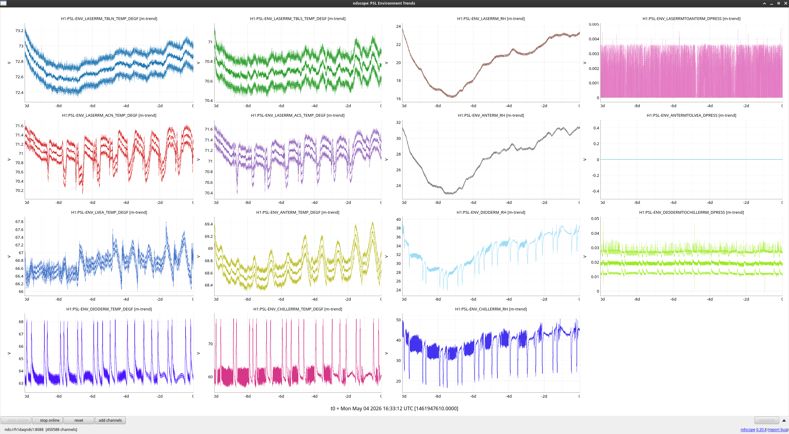
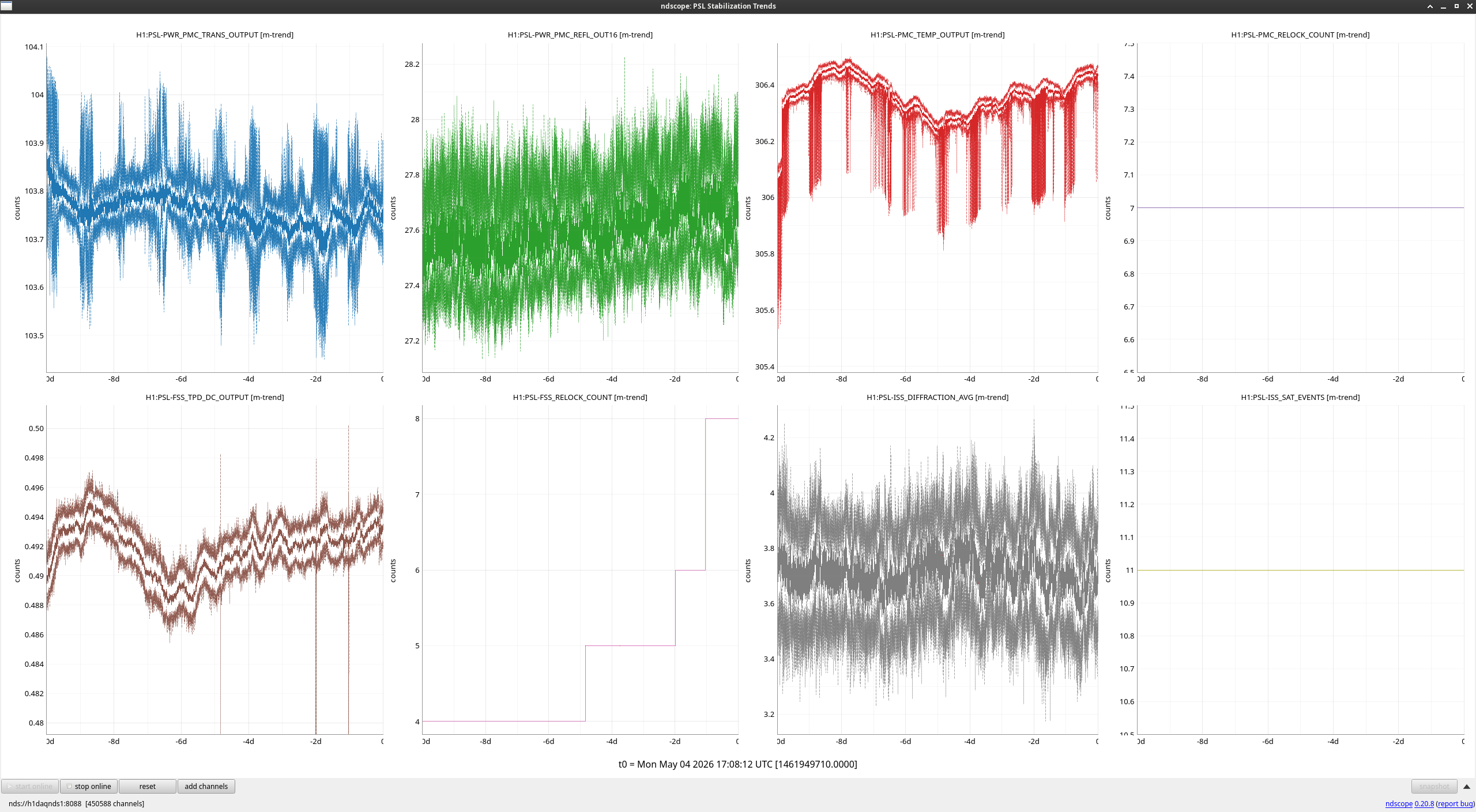
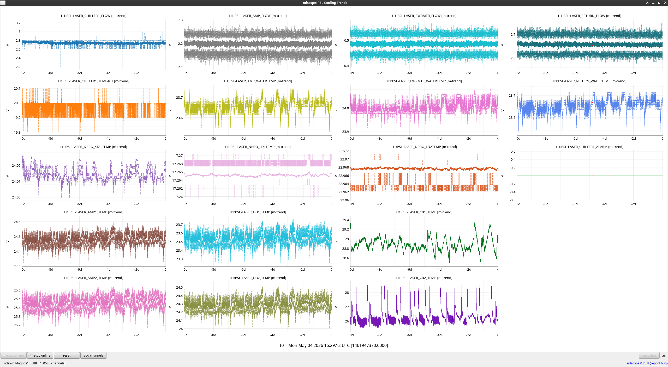
PSL 10-Day Trends

FAMIS 31136

No major events of note this week.

Images attached to this report
H1 General
jonathan.hanks@LIGO.ORG - posted 08:50, Monday 04 May 2026 (90100)
WP 13205 Migrated remote DMT access to LIGO.ORG Duo

As per WP 13205, remote ssh into the LHO DMT has transitioned from the old token authentication system to LIGO.ORG Duo.

H1 CDS
jonathan.hanks@LIGO.ORG - posted 08:49, Monday 04 May 2026 (90099)
WP 13118 finished migration to LIGO.ORG Duo for LHO CDS

As per WP 13118 CDS remote logins now require LIGO.ORG Duo.  CDS has been disconnected from the older token authentication system.

Remote ssh users who have not transitioned to LIGO.ORG Duo will need to do so.  See https://cdswiki.ligo-wa.caltech.edu/wiki/LigoOrgDuoSetup

If you have issues with logging in please let one of the CDS admins know.

H1 General
ryan.crouch@LIGO.ORG - posted 07:54, Monday 04 May 2026 (90098)
OPS MOnday Day shift start

TITLE: 05/04 Day Shift: 1430-2330 UTC (0730-1630 PST), all times posted in UTC
STATE of H1: Planned Engineering
OUTGOING OPERATOR: None
CURRENT ENVIRONMENT:
    SEI_ENV state: MAINTENANCE
    Wind: 3mph Gusts, 1mph 3min avg
    Primary useism: 0.02 μm/s
    Secondary useism: 0.18 μm/s 
QUICK SUMMARY:

H1 SUS (SUS)
thomas.roocke@LIGO.ORG - posted 18:04, Sunday 03 May 2026 - last comment - 19:06, Monday 04 May 2026(90097)
QOSEM Calibration Rig Setup

On Friday I setup the QOSEM calibration rig in the triple lab, in the staging building. It consists of a motorored translation stage (open loop picomotor), which drives the QOSEM flag into and out of the QOSEM body, while the sum and difference voltages produced by the sat amp are monitored. The position of the stage, and hence flag is readout by a Mach-Zender interferometer (SmarAct PicoScale). This is all controlled by a laptop running a python script.

The purpose of setting up this rig again is to better calibrate each QOSEM going on to the BBSS M1, by taking calibration data with the exact sat amp and flag that each QOSEM will use.

Comments related to this report
thomas.roocke@LIGO.ORG - 19:06, Monday 04 May 2026 (90114)

Today I finished setting up the QOSEM calibration rig in the triples lab. I grabbed the LHO production QOSEM sat amp from SUS-R2 for use in this calibration, and will match the flag and QOSEM pair to what they will be on the BBSS, such that the calibration is as valid as possible. The rig is all ready to go for calibration runs tomorrow.


Images attached to this comment
H1 CDS
david.barker@LIGO.ORG - posted 10:56, Sunday 03 May 2026 (90096)
PT100A added to alarms

Gerardo, Dave:

I have added the CP1 REGEN pump card gauge PT100A to alarms with Gerardo's requested alarm levels

<Channel name="H1:VAC-LY_Y5_PT100A_PRESS_TORR" low="1.0e-04" high="5.0e-01" fields="0" description="CP1 REGEN PUMP CART">

LHO VE
david.barker@LIGO.ORG - posted 10:24, Saturday 02 May 2026 (90095)
CP1 Fill Disabled, Did Not Run

During the CP1 Regen the daily fills have been disabled. Verified it did not run at 10:00 today.

Alarms has been configured to expect GV6 to be hard-closed. The bypass for this alarm has been removed.

H1 CDS
david.barker@LIGO.ORG - posted 09:24, Saturday 02 May 2026 (90094)
PT100A gauge MEDM, code fix installed

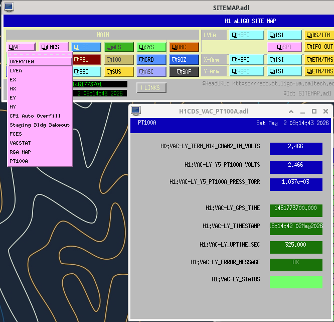
I've created an MEDM for the new PT100A EPICS IOC which reads the raw ADC Voltage from h0vacly (TERM14-CHAN2) and converts it to PRESS_TORR. It can be opened via the VE pull down on the SITEMAP (see attached).

The python code pt100a_ioc.py had a connection issue yesterday when we lost network connection to h0vacly during the closure of GV6. This resulted in a freeze of its value until I restarted the service Friday night at 20:50PDT.

Jonathan and myself installed a new version of the code this morning (Sat 02may2026 09:10 PDT) which should handle disconnection events gracefully.

I have added PT100A trending to ndshooter for 1 and 7 day lookbacks, e.g.  vac_pt100a_1_day.png (see attached, yesterday's value freeze clearly seen).

Images attached to this report
LHO VE (VE)
gerardo.moreno@LIGO.ORG - posted 17:58, Friday 01 May 2026 - last comment - 15:53, Monday 04 May 2026(90093)
CP1 Soft Regeneration Started

(Jordan V., Travis S., Dave B., Gerardo M.)

The CP1 soft regeneration officially started today at 4:56 pm local time, when we closed the bottom liquid draw valve.  We had a small issue with GV6 not wanting to hard close, we did two tries at hard closing this valve, it did close on the second try with a pressure of 65 psi.  The SS500 has been set to allow to pump despite the increase on pressure due to the lack of LN2 internal to CP1.  We used hoses to get the scroll pump exhaust out of the LVEA.  We will monitor the soft regeneration progress remotely.

Non-image files attached to this report
Comments related to this report
gerardo.moreno@LIGO.ORG - 09:44, Monday 04 May 2026 (90101)VE

Update

Regeneration process continues, no issues to report as of now.  Pressure internal to the cryotrap is now rising, see attached plot.  System was monitored remotely over the weekend.

Images attached to this comment
gerardo.moreno@LIGO.ORG - 15:53, Monday 04 May 2026 (90106)VE

CP1 exhaust pipes.No ice!

Images attached to this comment
H1 ISC
jennifer.wright@LIGO.ORG - posted 10:33, Friday 16 May 2025 - last comment - 16:42, Monday 04 May 2026(84432)
OMC scans with SR3 heater on

Jennie W, Sheila, Elenna


In order to get data for mode-matching and for Elenna to get data to calibrate sideband heights we ran some mode scans after the SR3 heater was turned on last night.

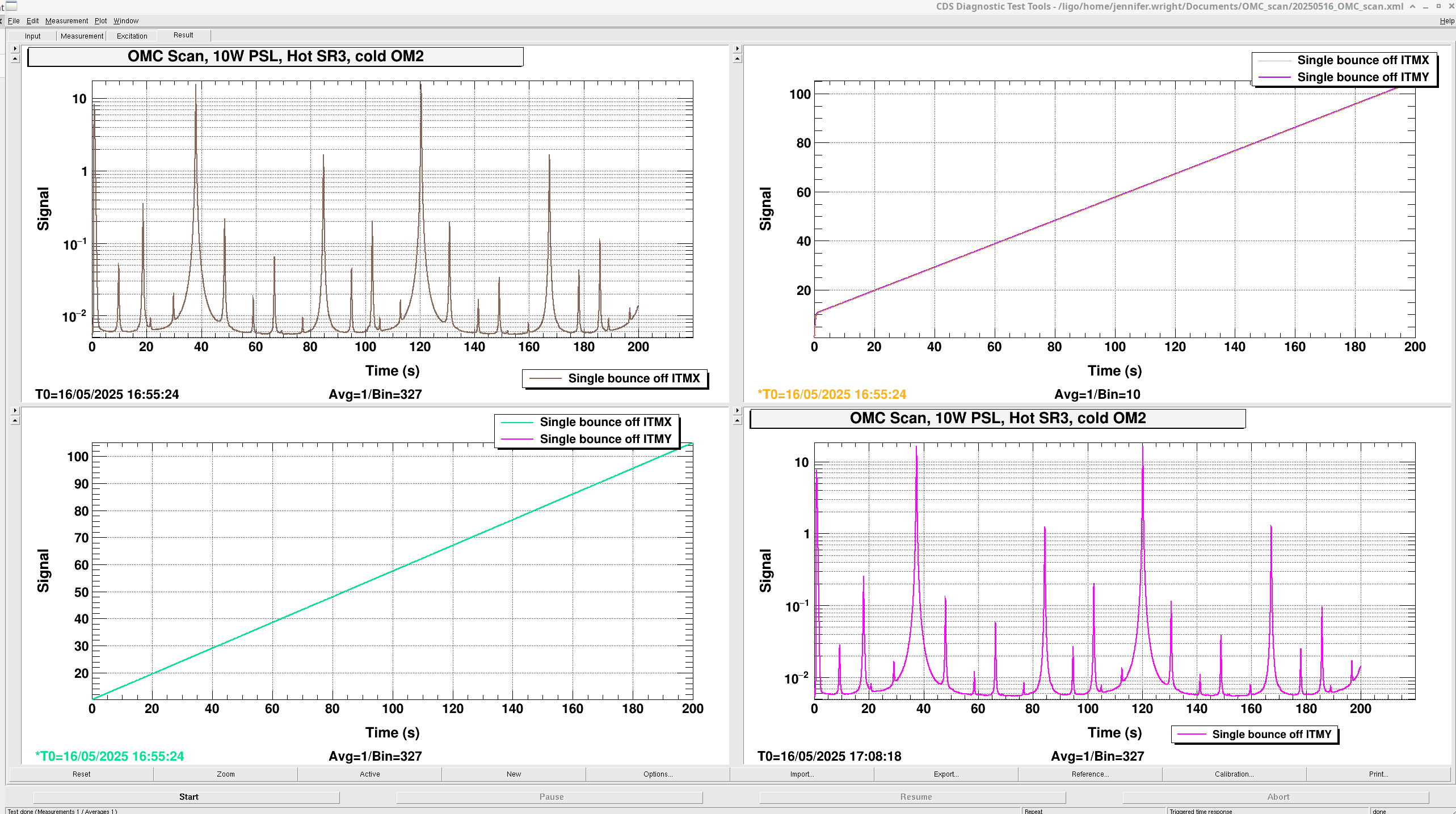
16:55:24 UTC Carried out single bounce OMC scan at 10W PSL input with sensor correction on HAM6 on, high voltage on for PZT driver in HAM6, sidebands off , SRM mis-aligned, ITMY mis-aligned, DC 3 and 4 on, OMC ASC on.

Excitation freq changed to 0.005 Hz as the top peak of the TM00 mode looked squint so could have been saturating. Lowering this frequency prevented this.

Ref 15-17 corresponds to dcpd data, pzt exc signal, pzt2 dc monitor.


Then mis-aligned ITMX and aligned ITMY (Sheila had to re-align SR2 to centre on ASC-AS_C).

Measurement starts at 17:08:18 UTC.

Ref 18-20 corresponds to dcpd data, pzt exc signal, pzt2 dc monitor.


Traces saved in 20250516_OMC_scan.xml. The top left plot is the first scan bouncing beam off ITMX, the second scan is the bottom right bouncing off ITMY.

The top right is the two plots of the PZT2 DC voltage monitor. That is, the current voltage applied to the PZT. The bottom left is the plot of the voltage ramp applied to the PZT2 on the OMC for this measurement.


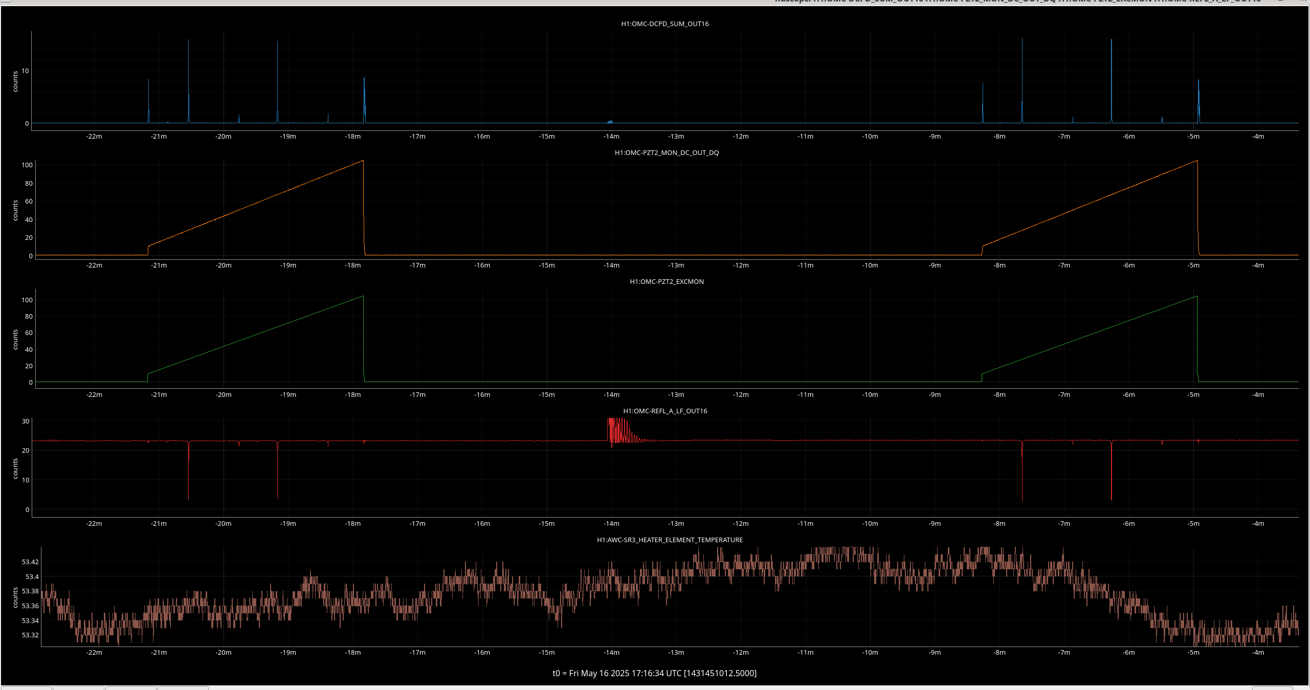
The ndscope attached shows the power in mA transmitted through the OMC on the top, then the PZT used for the scan DC voltage underneath, then the input PZT voltage underneath that, then the reflected power from the OMC in mW, then at the bottom the SR3 heater element temperature in degrees.


Elenna did two more scans in single bounce with sidebands back on and different modulations depths in each.

Images attached to this report
Comments related to this report
jennifer.wright@LIGO.ORG - 10:38, Friday 16 May 2025 (84433)

See Elenna's comment on her previous measurement where this saturation happened.

Turn off the sidebands - instructions in this alog.

elenna.capote@LIGO.ORG - 16:51, Friday 16 May 2025 (84441)

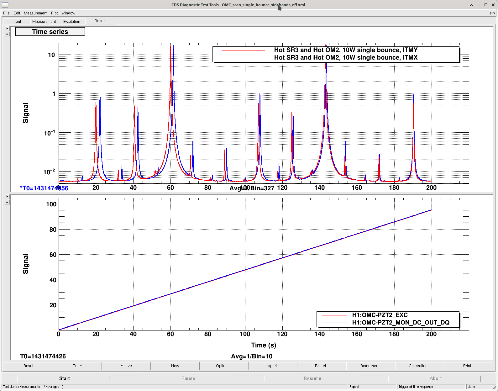
Sheila and I ran one more OMC scan with sidebands off after OM2 heated up. Attached is the screenshot with scans off both ITMX and ITMY, data is saved in [userapp]/omc/h1/templates/OMC_scan_single_bounce_sidebands_off.xml


Images attached to this comment
elenna.capote@LIGO.ORG - 17:02, Friday 16 May 2025 (84442)

I also ran two OMC scans, single bounce off ITMY, 10 W input, with the sidebands ON. One measurement I ran with the sidebands set to 23 dBm and 27 dBm (9 and 45 MHz) and another set to 20 dBm and 21 dBm (9 and 45 MHz). I will use these measurements to calibrate the modulation depth. Data saved in /opt/rtcds/userapps/release/omc/h1/templates/OMC_scan_single_bounce_RF_cal.xml

SR3 heater was on for this measurement but it should have little effect on my results.

camilla.compton@LIGO.ORG - 11:40, Tuesday 03 June 2025 (84749)

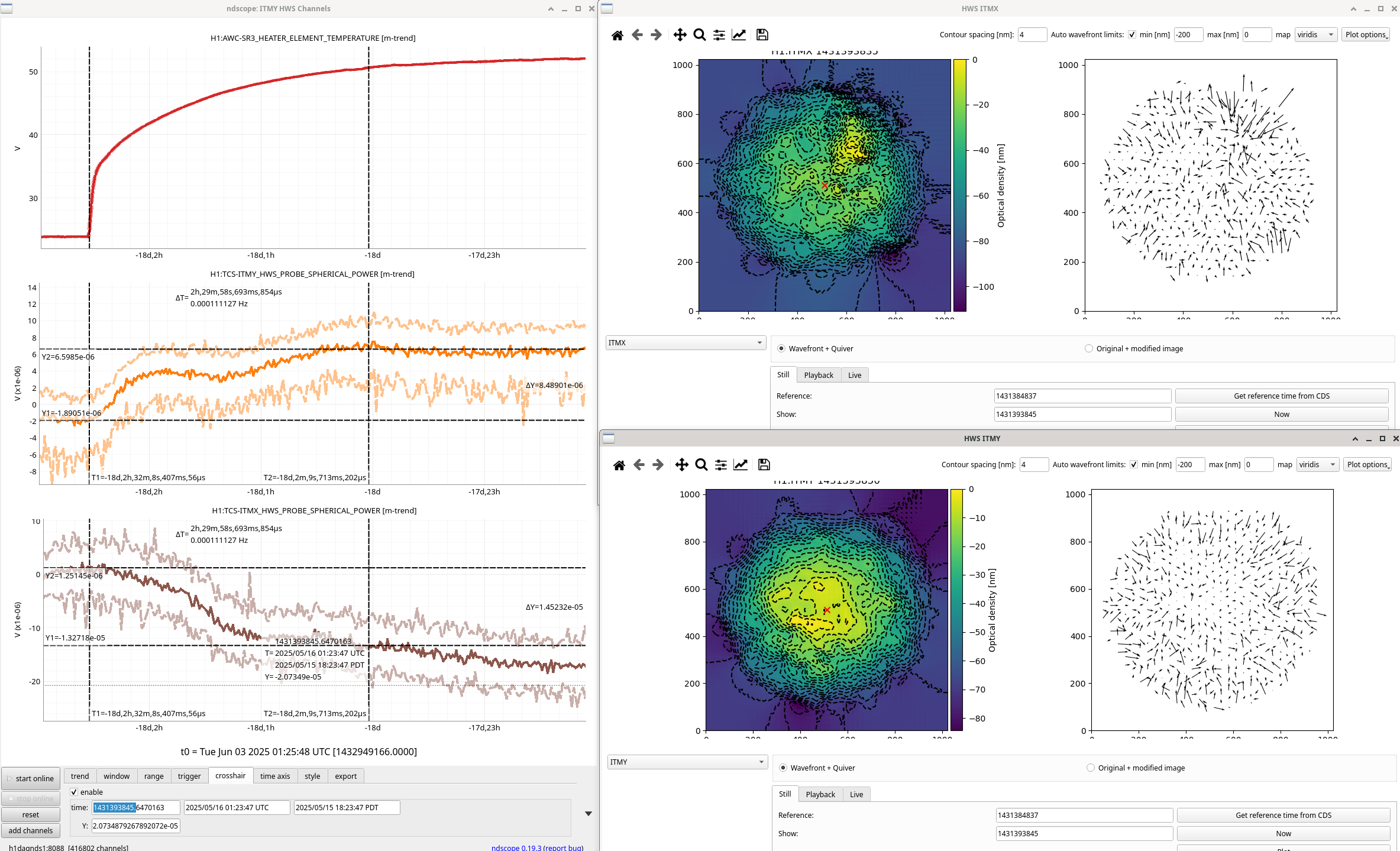
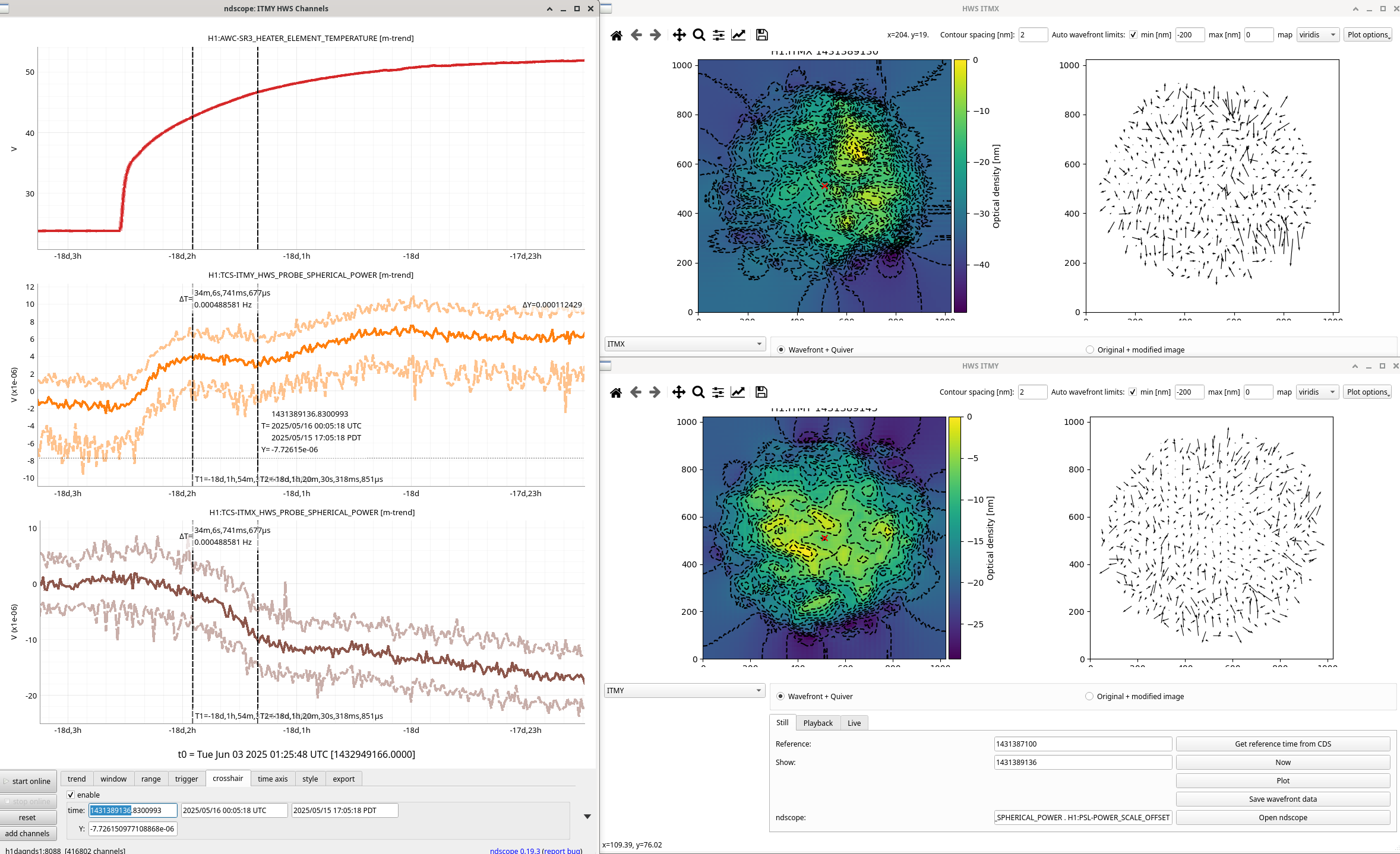
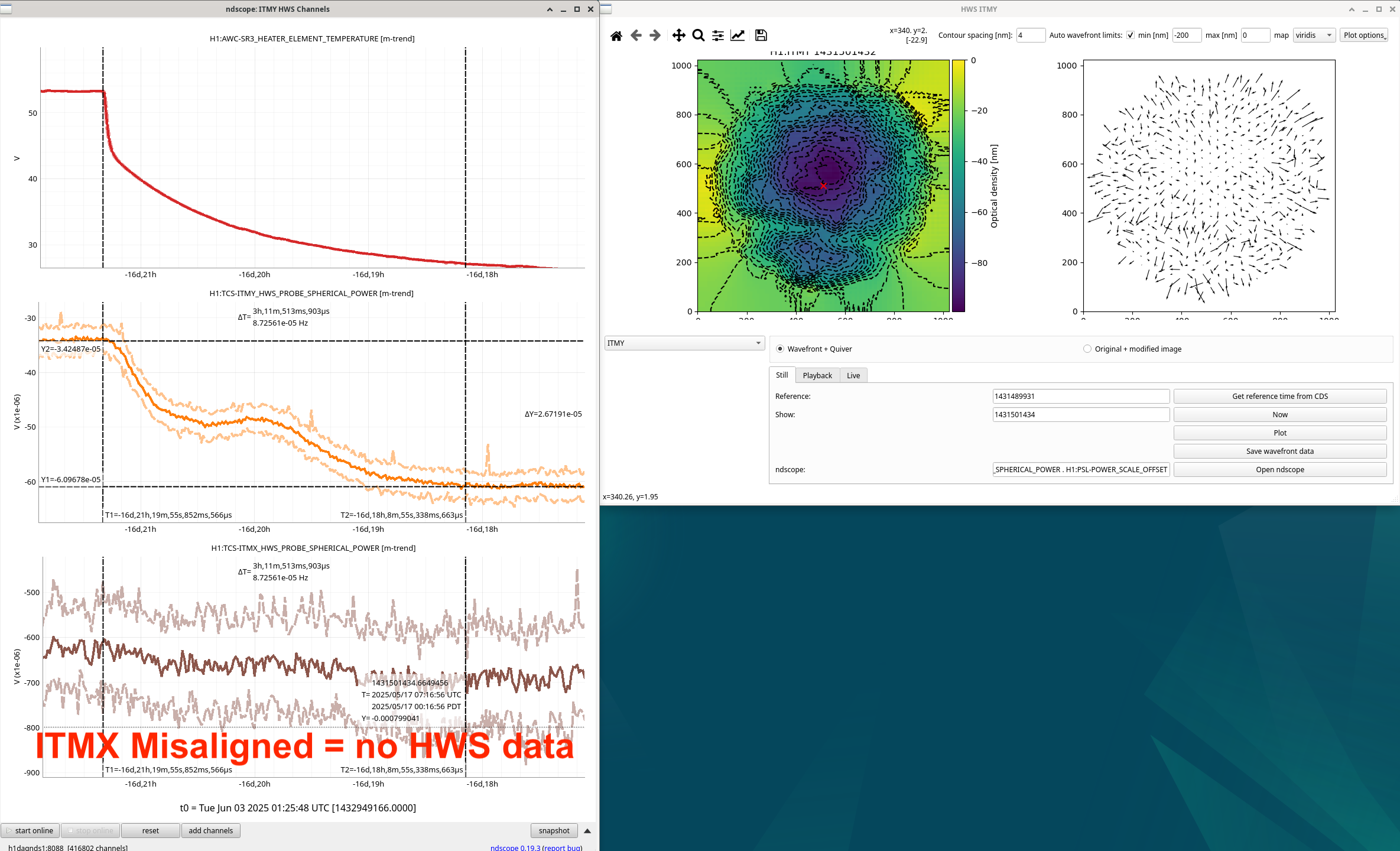
Looked closer at these HWS signals during SR3 heater heat up and cool down. In all these plots, the two t-cursors are used as the reference and shown HWS live image.

  • Heat up plot attached
  • Cool down plot attached (ITMX was misaligned so there's no HWS data)

Some strange things:

  • ITMX heat up ndscope spherical power looks the opposite direction of ITMY, this isn't physical. Looking at the HWS Live plot, this isn't really want's happening, it appears that the SR3 signal just appears if the edge of ITMX is heating up so the center that the calculations are made from isn't correct, making the calculated spherical power wrong.
  • In both the heat up and cool down of the ITMY signal, there appears to be two steps with a flat region in the middle. Looking at the the flat region only, attached, it appears that the spherical power is continuing to change in the expected direction, unsure why this change isn't shown in the calculated spherical power.
Images attached to this comment
jennifer.wright@LIGO.ORG - 12:09, Thursday 10 July 2025 (85661)

Finally got round to fitting the two single bounce mode scans done with SR3 hot and OM2 cold. The first we had ITMX aligned, the second we switched to ITMY aligned.

These can currently be processed using OMCscan.py in the /dev branch for the labutils/omcscan repository at /ligo/gitcommon/labutils/omc_scan, you need to have activated the labutils conda environment to do so.

The call statements for the data processing are:

python OMCscan.py 1431449762 130 "1st 1431449762 - SR3 hot, 10W PSL, ITMY mis-aligned" "single bounce" -s -v -o 2 -m 

python OMCscan.py 1431450536 140 "2nd 1431450536 - SR3 hot, 10W PSL, ITMX mis-aligned" "single bounce" -s --verbose -m -o 2

For each measurement the tag -s specifices that the sidebands were not on and so in order to calibrate the PZT the code uses the two TM00 modes and then you have to tell it in what height order the 10 and 20 modes appear relative to the highest peak which will be one of the 00 modes.

def identify_C02(self):

"""If in single bounce configuration, and with sidebands off,

identify 10 and 20 modes in order to improve fit.

Assumes that

OMCscan.identify_peaks()

and

OMCscan.identify_carrier_00_peaks()

have already been run.


Output:

-------

self.peak_dict: dictionary

first set of keys are carrier, 45 upper, 45 lower

second set of keys are TEM mode, e.g. "00", "01", "20", etc.

third set of keys is the fsr number

"""


# Create temporary dictionary to combine into self.peak_dict

peak_dict = {}

peak_dict["carrier"] = {"10": {}, "20": {}}

#print(peak_dict)

nn = [2, 1]

mm = 0

#freq_diff = np.empty(np.size(self.peak_frequencies)) not sure why this line here.

#set frequency to be that of third largest peak.

first_order = np.argsort(self.peak_heights)[-4]#-4 for second meas.

second_order = np.argsort(self.peak_heights)[-3]#change index to match where 20 is in terfirst meas if measuring from start of scan.ms of peak height.

#print(third_larg)

for ii, peak_freq in enumerate(self.peak_frequencies):

if peak_freq == self.peak_frequencies[second_order]:

#print("found C02")

#print(f"List fields in IFO {self.fields_MHz}")

#print(type(self.fields_MHz))

#print(f"OMC HOM spacing {self.omc_hom} MHz")

#print(type(self.omc_hom))

field = f"carrier"

#print(f"mode {field}{nn[0]}{mm}")

peak_dict[field]["20"][-1] = {

"height": self.peak_heights[ii],

"voltage": self.peak_pzt_voltages[ii],

"frequency": self.peak_frequencies[ii],

"true_frequency": np.mod((self.fields_MHz - (nn[0] + mm) * self.omc_hom), self.omc_fsr),

"label": r"$c_{20}$",

}

self.peak_ided[ii] = 1

elif peak_freq == self.peak_frequencies[first_order]:

field = f"carrier"

peak_dict[field]["10"][-1] = {

"height": self.peak_heights[ii],

"voltage": self.peak_pzt_voltages[ii],

"frequency": self.peak_frequencies[ii],

"true_frequency": np.mod((self.fields_MHz - (nn[1] + mm) * self.omc_hom), self.omc_fsr),

"label": r"$c_{10}$",

}

self.peak_ided[ii] = 1

else:

continue

# Merge dictionaries

#if not "20" in peak_dict["carrier"].keys():

self.peak_dict["carrier"] = {**self.peak_dict["carrier"], **peak_dict["carrier"]}

#print(self.peak_dict)

#print(self.peak_ided)

return


For both measurements I only took slightly over 1 FSR of the data, this is because in order to fit a polynomial to the known peaks (allowing us to calculate the PZT non-linearity), the code assumes the 1st order is the 3rd highest and 2nd order is the 4th highest.  In the code above you need to change the indexes in the below lines to match the height order of the peaks (ie. and index of -4 is fourth highest peak).

first_order = np.argsort(self.peak_heights)[-4]

second_order = np.argsort(self.peak_heights)[-3]

When the mode-matching is bad this may not be true, also if there are multiple FSRs in the scan this also may not be true.


First measurement 1st order mode is fifth highest, 2nd order mode is third highest. The scan is here. I took 130 s of data. The PZT fit is here.

Second measurement the 1st order mode was the 4th highest, 2nd order mode was the third highest. The scan is here. I took 140s of the scan data. The PZT fit is here.


Non-image files attached to this comment
jennifer.wright@LIGO.ORG - 11:52, Friday 11 July 2025 (85693)

First measurement has 

1.69/(1.69+15.86) = 9.63 % mode mis-match.


Second measurement has 

1.25*100/(1.25 + 16.46) = 7.06 % mode mis-match


jennifer.wright@LIGO.ORG - 15:56, Friday 11 July 2025 (85698)

I also analysed the single bounce measurements Elenna and Sheila made after OM2 was heated up. So these have both SR3 and OM2 hot.

For both these measurements C02 was the third highest mode and C01 was the fourth highest. I took 120s starting 45s into the scan.


Measurement 1: 23:40:38 UTC on 2025/05/16 with ITMX aligned and ITMY mis-aligned.

See the spectrum with labelled peaks here.

And the PZT calibration here.

Mode mis-match is: 

0.93/( 0.93 + 17.29 ) = 5.10 %


Measurement 2: 23:46:48 UTC on 2025/05/16 with ITMY aligned and ITMX mis-aligned.

See the spectrum with labelled peaks here.

And the PZT calibration here.

100 * 0.56/( 0.56 + 17.62 ) = 3.08 %

Bear in mind that this is assuming that there is no astigmatism in the OMC (since there is but we cannot resolve 02 vs 20 modes). This requires some careful analysis of uncertainties to get useful info about how we should tune for better mode-matching. Watch this space.

Non-image files attached to this comment
sheila.dwyer@LIGO.ORG - 08:58, Wednesday 15 April 2026 (89897)

In these scans the SR3 heater request (POWER_SET) was 2W, the readback power monitor reports 1.9W. 

craig.cahillane@LIGO.ORG - 16:42, Monday 04 May 2026 (90109)
Using the data from Elenna's scans with the sidebands on, I added a function calculate_modulation_depths() to the OMCscan.py code.
I then used it to find the modulation depths for the 9 and 45 MHz from those scans:

PDH measurement data for two GPS timestamps

Parameter GPS 1431450833 GPS 1431451160
Slider 9 MHz 23.4 dBm 20.4 dBm
Slider 45 MHz 27.0 dBm 21.0 dBm
Modulation depth 9 MHz 0.215 rad 0.165 rad
Modulation depth 45 MHz 0.277 rad 0.145 rad
Displaying reports 901-920 of 88435.Go to page Start 42 43 44 45 46 47 48 49 50 End