Camille (CIT), Austin , Rahul
This morning we went to HAM7 chamber and changed the preload on ZM4 (P-SAMS) suspension as per the document E2300463_V1. This changed the RoC of ZM4 mirror without the PZT actuation. Given below are the details of our work - Camille will add pictures later on.
- After setting ZM4 into SAFE state we locked all three stages of the suspension. We had already taken healthy TF measurements before starting our work.
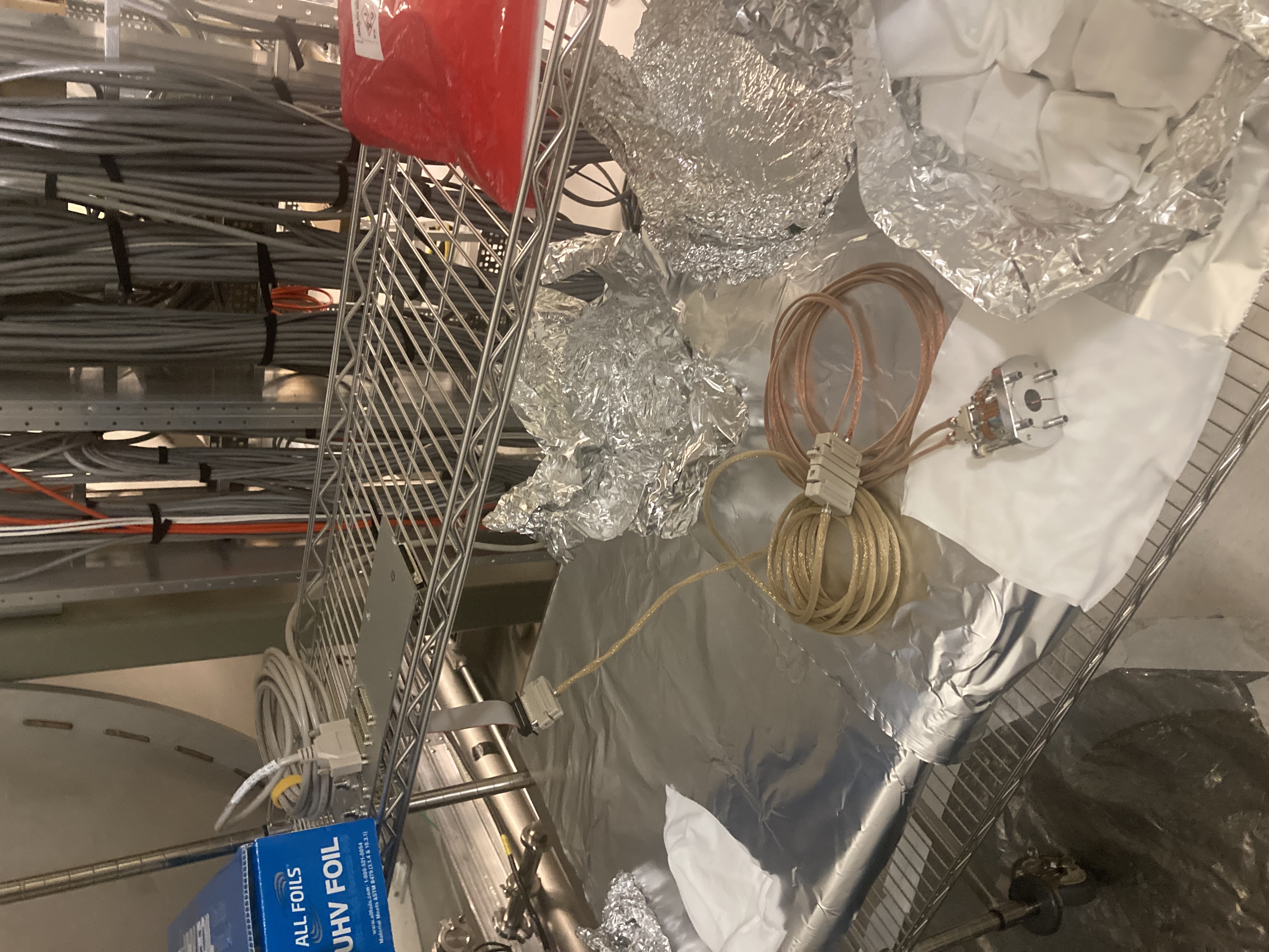
- The bottom mass cable was disconnected and carefully re-routed so that it stays away from the fixture plate.
- four add-on masses (basically 1/4-20 screws with washers) attached to the bottom mass was then removed.
- bottom mass Fixture plate (D2100121) was attached to the structure using six 8-32 screws.
- The bottom mass (already locked using EQ stops) was then further clamped using four 1/4-20 screws through the fixture plate. We had to adjust the height of the bottom mass to the align the threads with the holes on the fixture plate.
- Once the bottom mass was securely clamped, we removed the three set screws on the preloader.
- Using a torque wrench we increased the preload on the bottom mass by ~29 in.lb. (Total preload from torque after increase was 75 in.lb).
- We then followed all the above steps backwards (i.e set screws, add on mass put back, fixture plate removed, cable re-connected and the suspension set free).
- Once all done, we started damping the suspension and checked for any BOSEM flag changes - looked all fine.
- We took the transfer function measurements and ZM4 looked healthy.
Hence we took all the tools out and put the curtains back on HAM7 chamber.
Next, we will go into laser hazard with SQZ team and check for any changes in beam alignment and make adjustments as required.


