Jennie W, Jeff Kissel,
Summary: Can we see a difference in jitter with JAC in the IMC ASC sensors? Short answer, yes.
The IMC has less angular motion with JAC installed at some frequencies - jitter is being suppressed by the JAC so less input beam motion relative to the cavity axis. The QPD readouts are noisier with JAC but there is one new suspension between JAC and the IMC so maybe the beam pointing to MC1 is noisier? MC2 TRANS QPD looks pretty similar with and without JAC, but this makes sense as cavity axis is still well aligned to this QPD. I need some other figure of merit to look at jitter as it only limits the IFO above 20 Hz, see alog #86555 by Sheila.
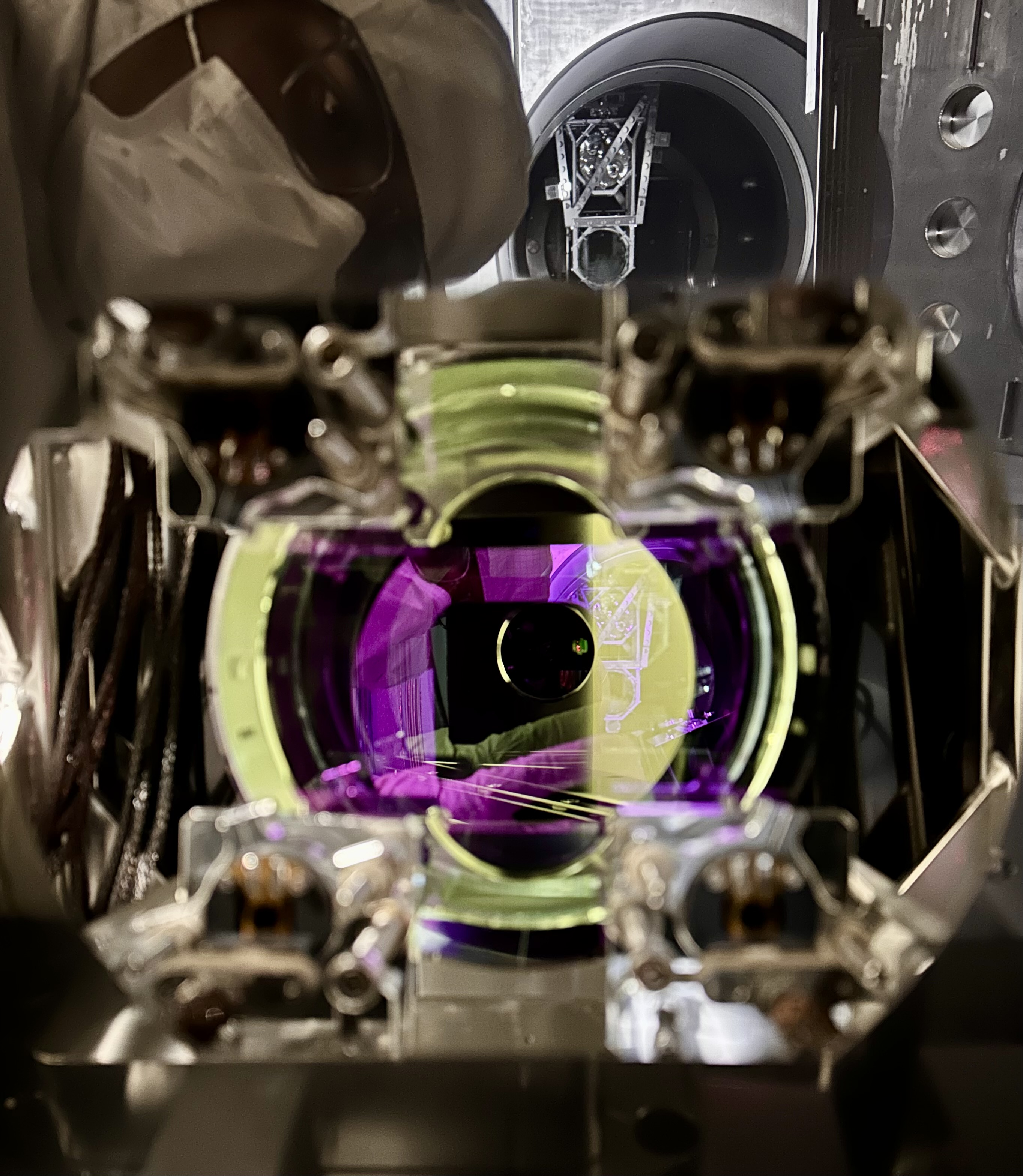
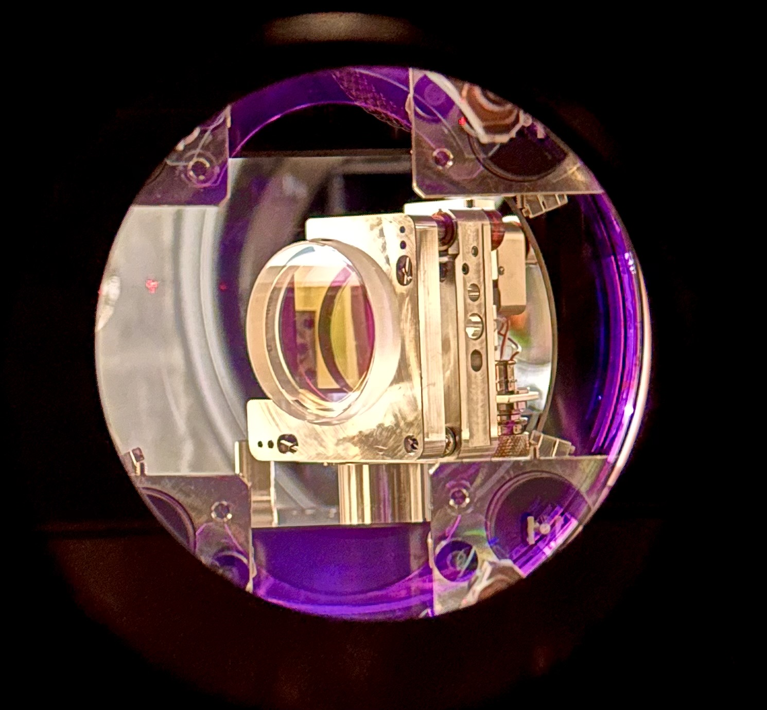
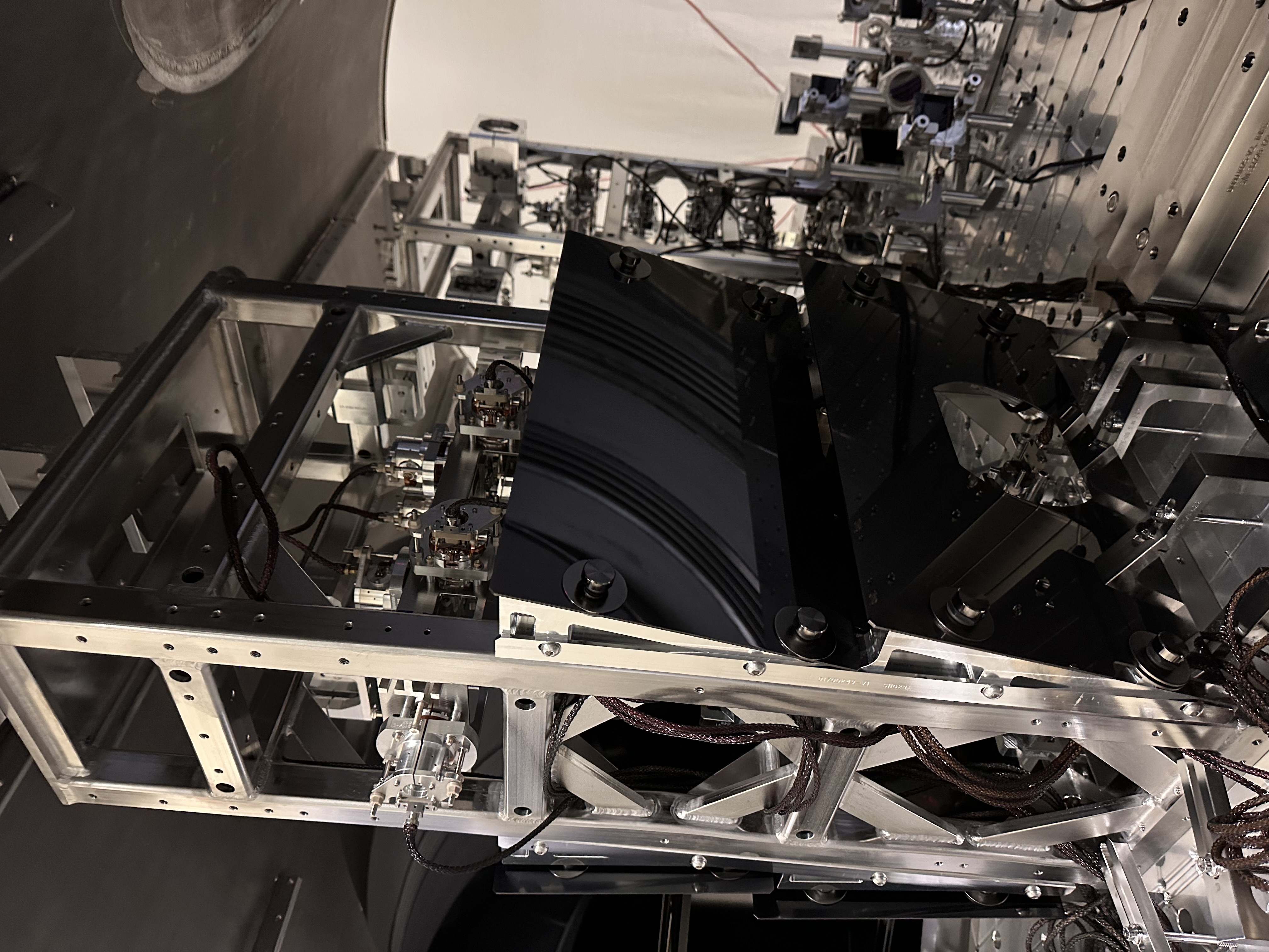
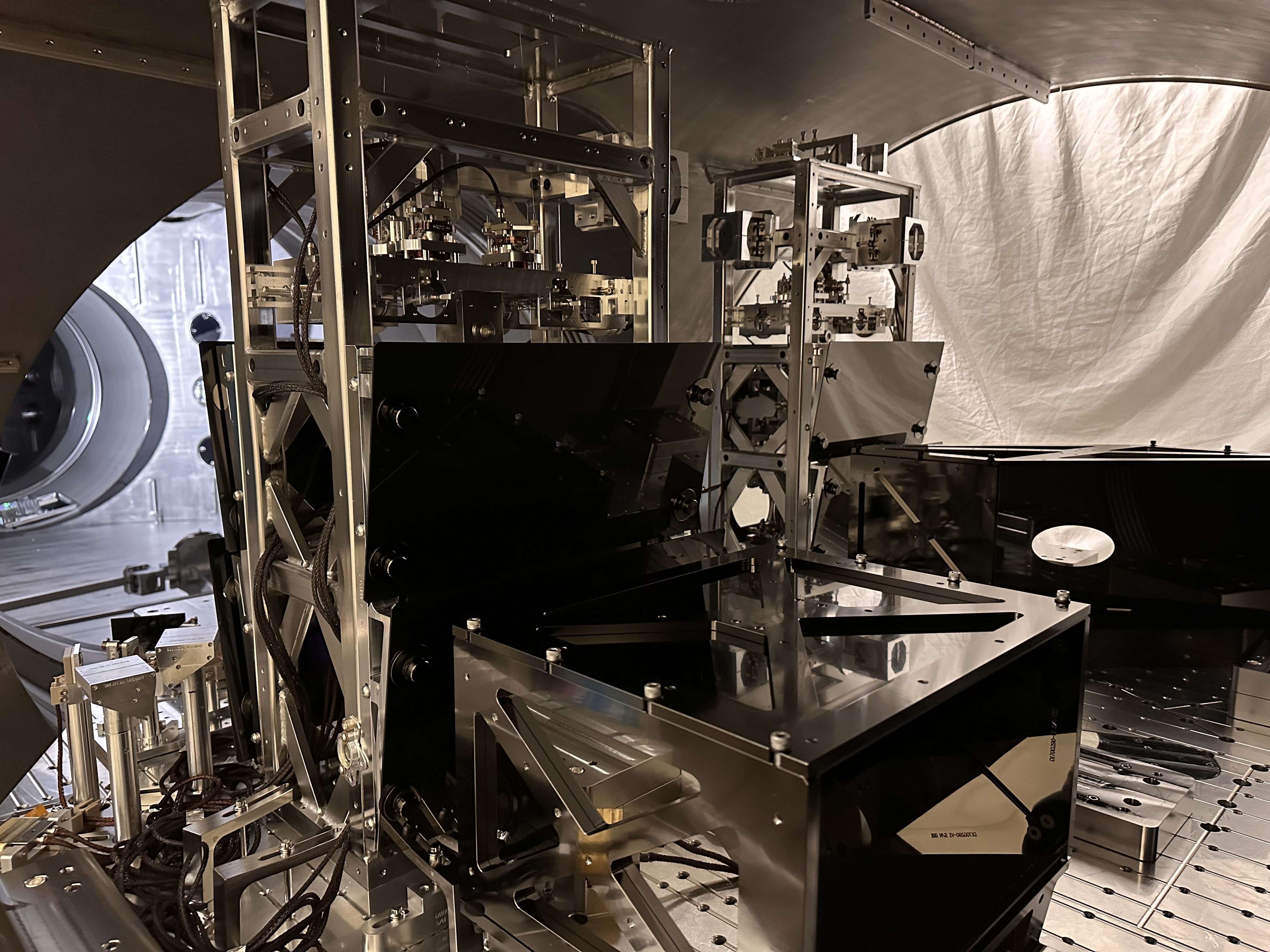
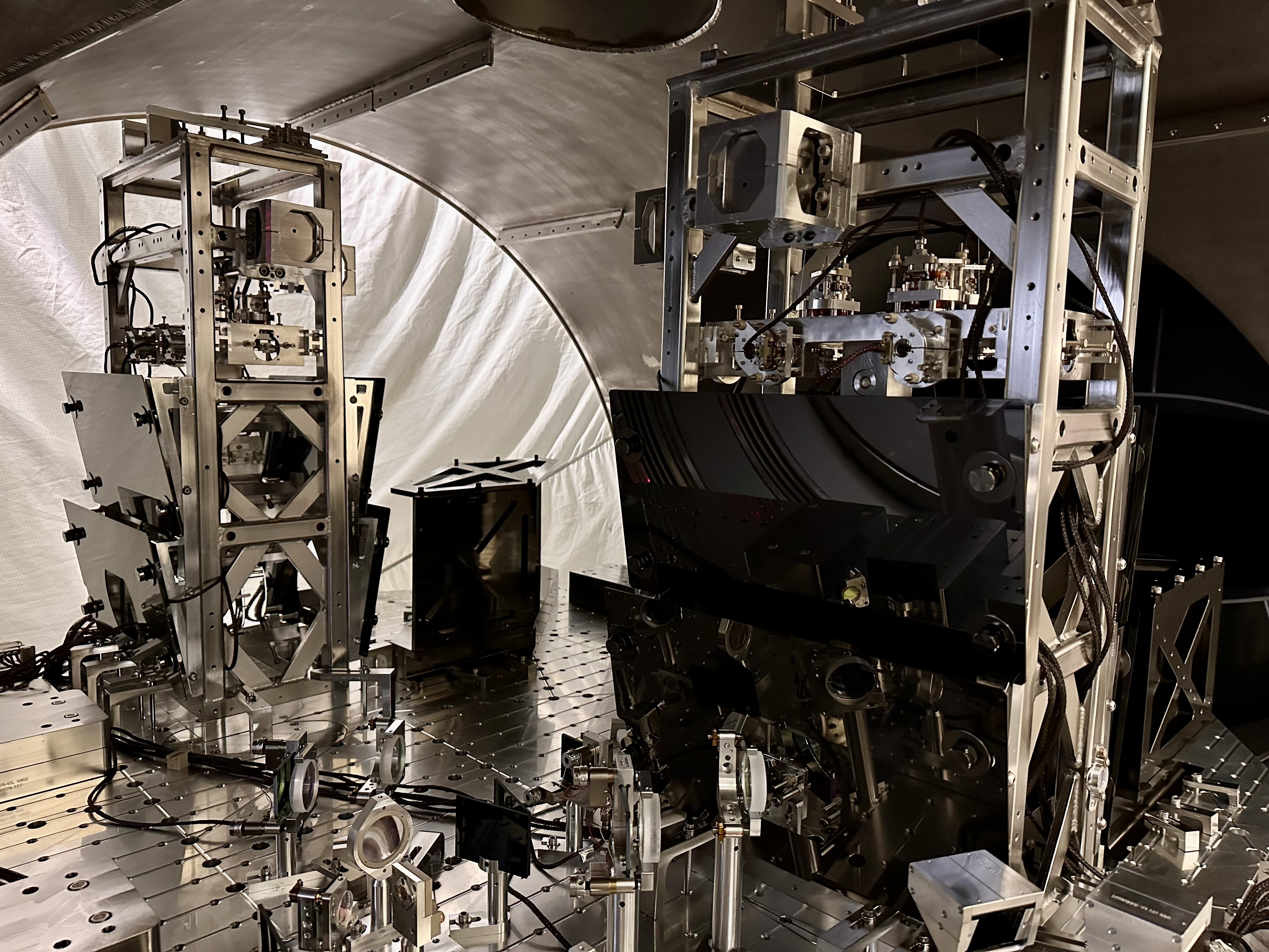
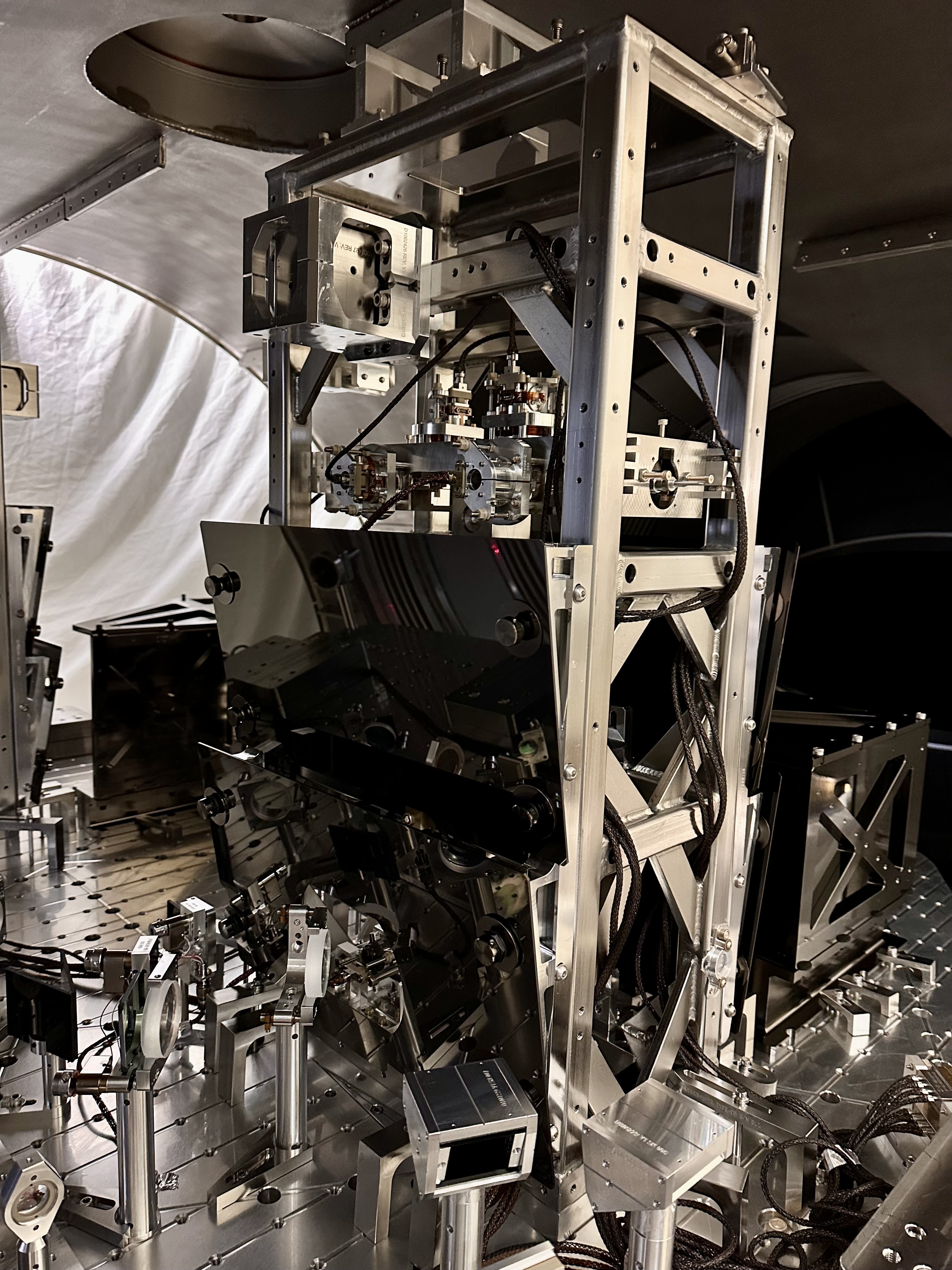
Since there was no time for a full IFO lock betwen the HAM1 vent and the current vent of the corner volume, we cannot directly check whether the jitter coupling to DARM is better with the JAC cavity.
We have lots of data of the JAC and IMC locked after the installation of JAC, however.
So I compared two times when we had roughly 2W input from the PSL to HAM1. In both cases H1 and the corner were at vacuum to rule out confounding effects from purge air and other sound noise seen when HAM1 was at air.
In both these cases the IMC was locked.
The two times I used were:
2025/11/17 15:38:54 UTC no JAC, during O4c
2026/03/20 00:26:01 UTC JAC installed, HAM1 at vacuum
Here is the ASD measurements for five sensors in the pitch degree of freedom:
IMC REFL WFS A Roughly the same above 10Hz with and without JAC. Better with JAC between 0.3 and 7Hz.
IMC REFL WFS B Roughly the same above 10Hz with and without JAC. Better with JAC below 7Hz.
IMC REFL QPD A has lower noise now below 5Hz than before JAC installation and much higher noise at frequencies above 10Hz.
IMC REFL QPD B has lower noise now below 3Hz than before JAC installation and much higher noise at frequencies above 10Hz.
MC2 TRANS QPD roughly the same with and without JAC.
Jitter noise is more of a problem in the 20-800 Hz region, which these plots don't tell us much about.
I also need the check YAW


