Follow on from 90719. Jennie, Keita, Betsy, Sheila, Camilla, Ryan S, Oli, Arnaud
Before doing any more mechanical BS offloading, we decide to put ITMX back too it's March DRMI top mass osems values, as described in alog90708, we expected we'd need to move ITMY to compensate for this, but did not.
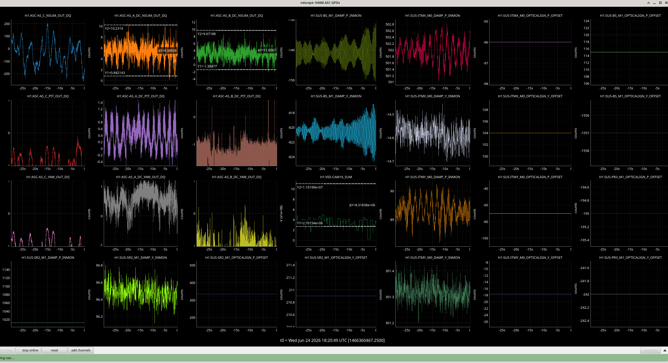
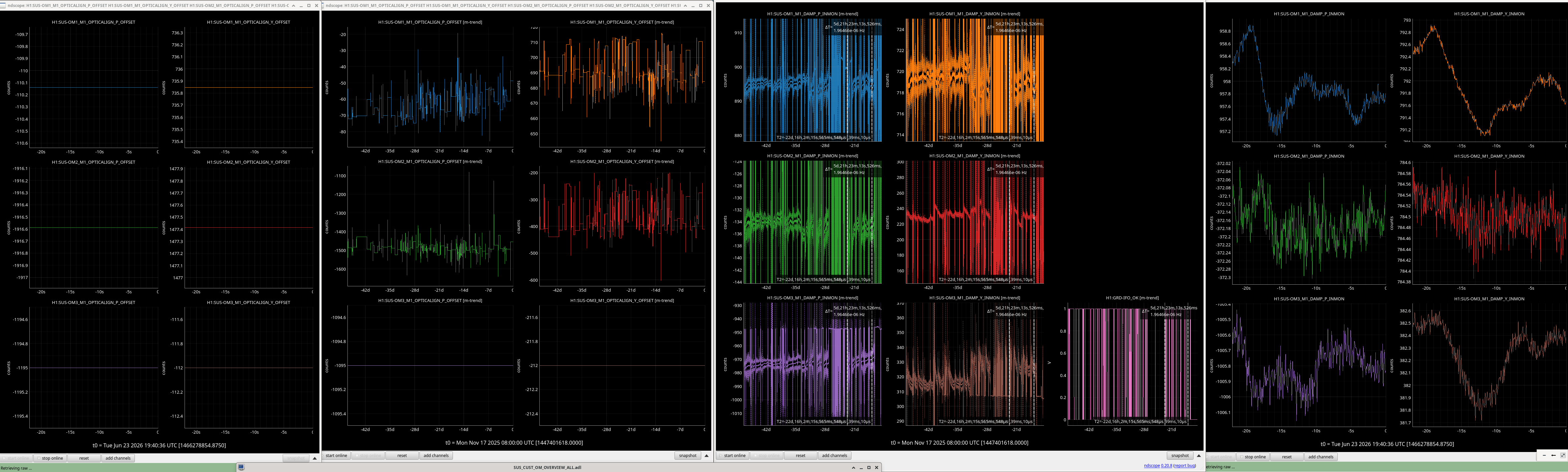
Used the SQZ beam. Mis-aligned ITMY. Moved ITMX towards correct Pit value. Compensated with BS Pitch and Yaw to keep beam on AS AIR. Moved PR3 to keep beam on ISCT1 REFL camera. We did not fine tune fringing. Keita opened PSL light pipe an further tuned PR3 to get PSL beams both on cameras. Ending sliders here. Ndscope of the fringing on AS_A/B here.
BS pitch is now close enough we will do no further mechanical pitch offloading now, it will be Yaw offloaded SEI system. Arnaud checked the oplevs to known that for the -1500 counts of BS yaw slider, this is ~ 2.5mrad.
Both ITMX and ITMY are now at their March DRMI top mass osems locations (11:02 PDT 19 March 2026).
|
Starting today
|
After ITMX moved back to DRMI M0 OSEMs
|
|
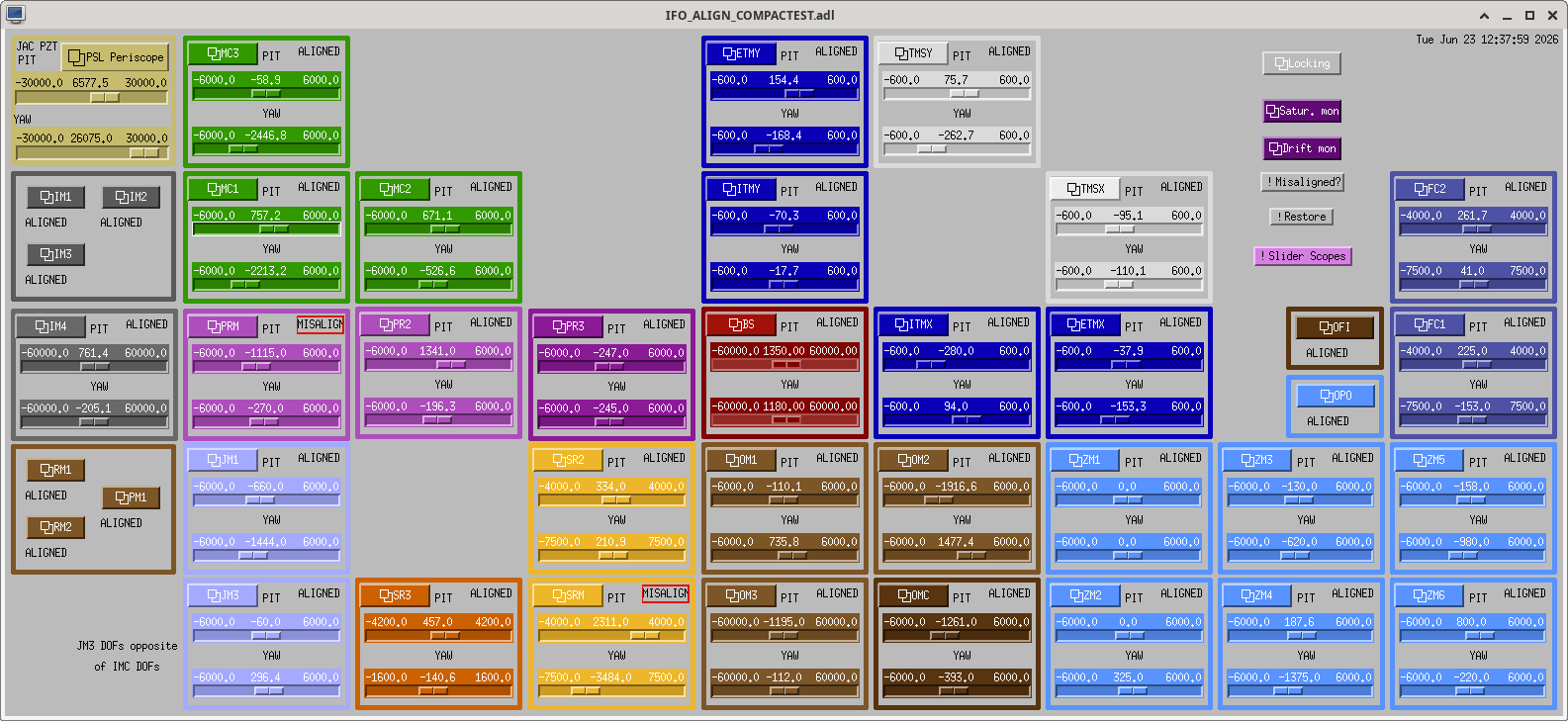
| ITMX |
P -280, Y +94
|
P -96, Y +104
|
| BS |
P +520, Y -1677
|
P +115, Y -1557
|
| PR3 |
P -247, Y -245
|
P -195, -242
|


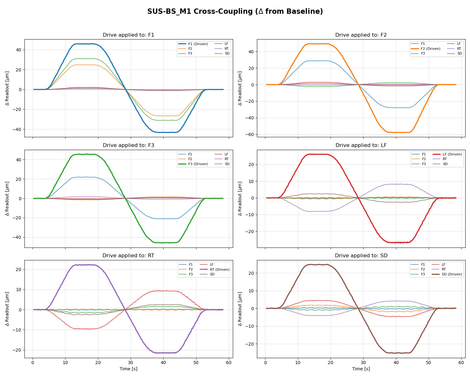
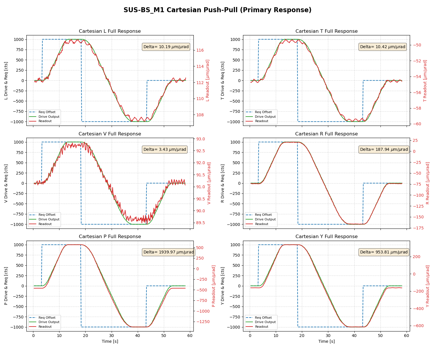
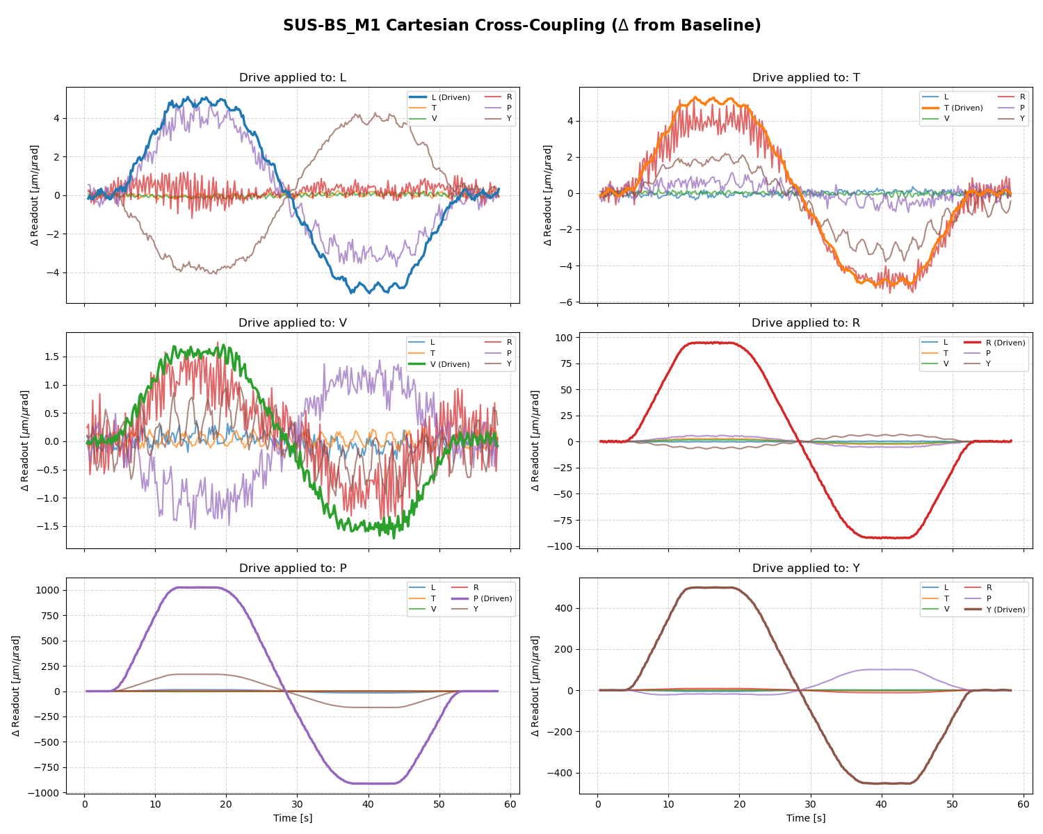
Given this calibration the newest BS offsets (P +115, Y -1557) [cts] corresponds to the calibrated offsets (P +17.25, Y -2569) [urad at M3] when only considering the P2P and Y2Y calibration. When taking into account the cross coupling those offsets are (P -138, Y -2529) [urad at M3].
This defines the amount of yaw motion (and direction) to offload this offset with HEPI : Rotate HEPI ~2.5mrad clockwise


