I've been trying to understand how to make estimates of actuation strength for thermal actuators, and I wanted to make a summary to make this easier in the future. With .
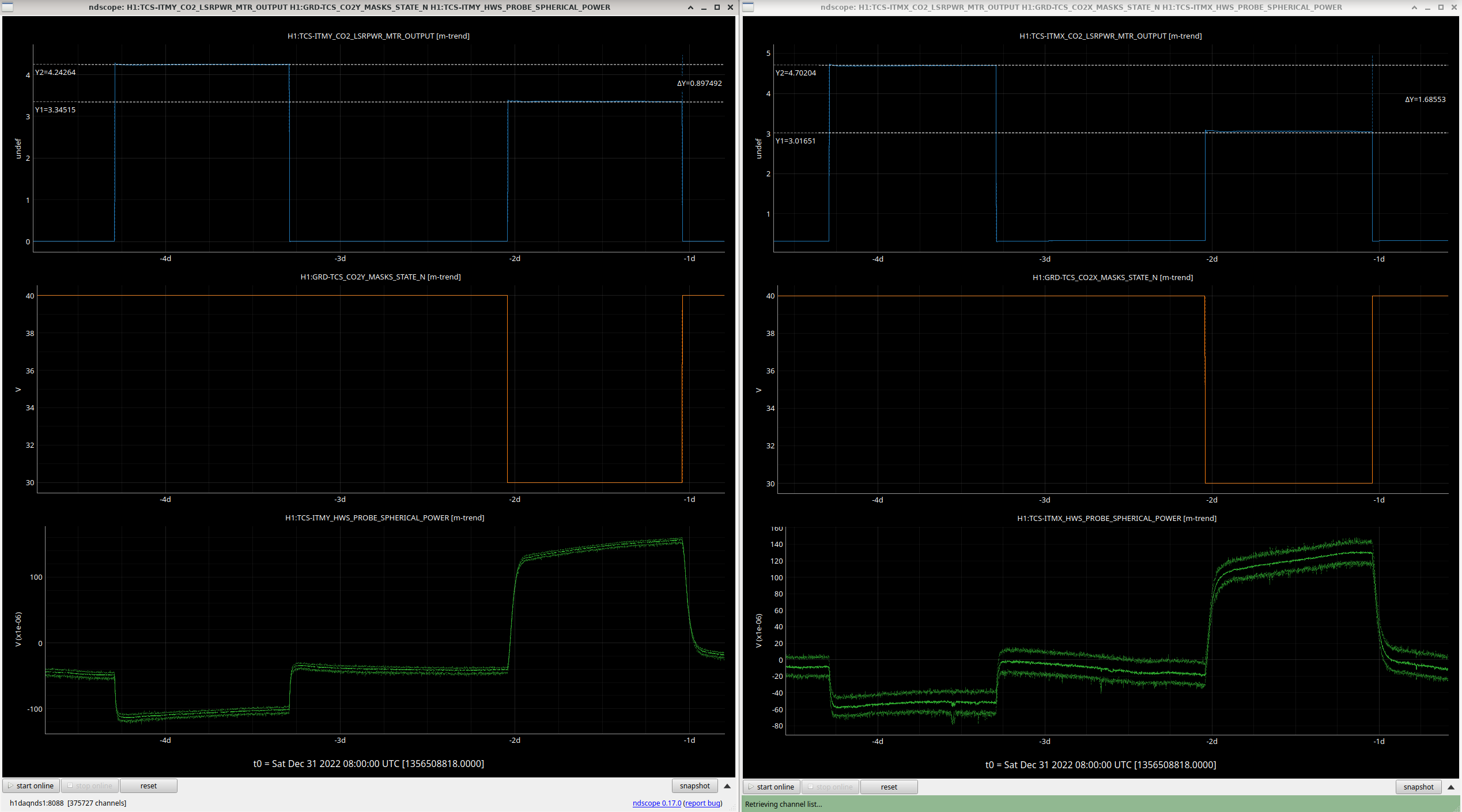
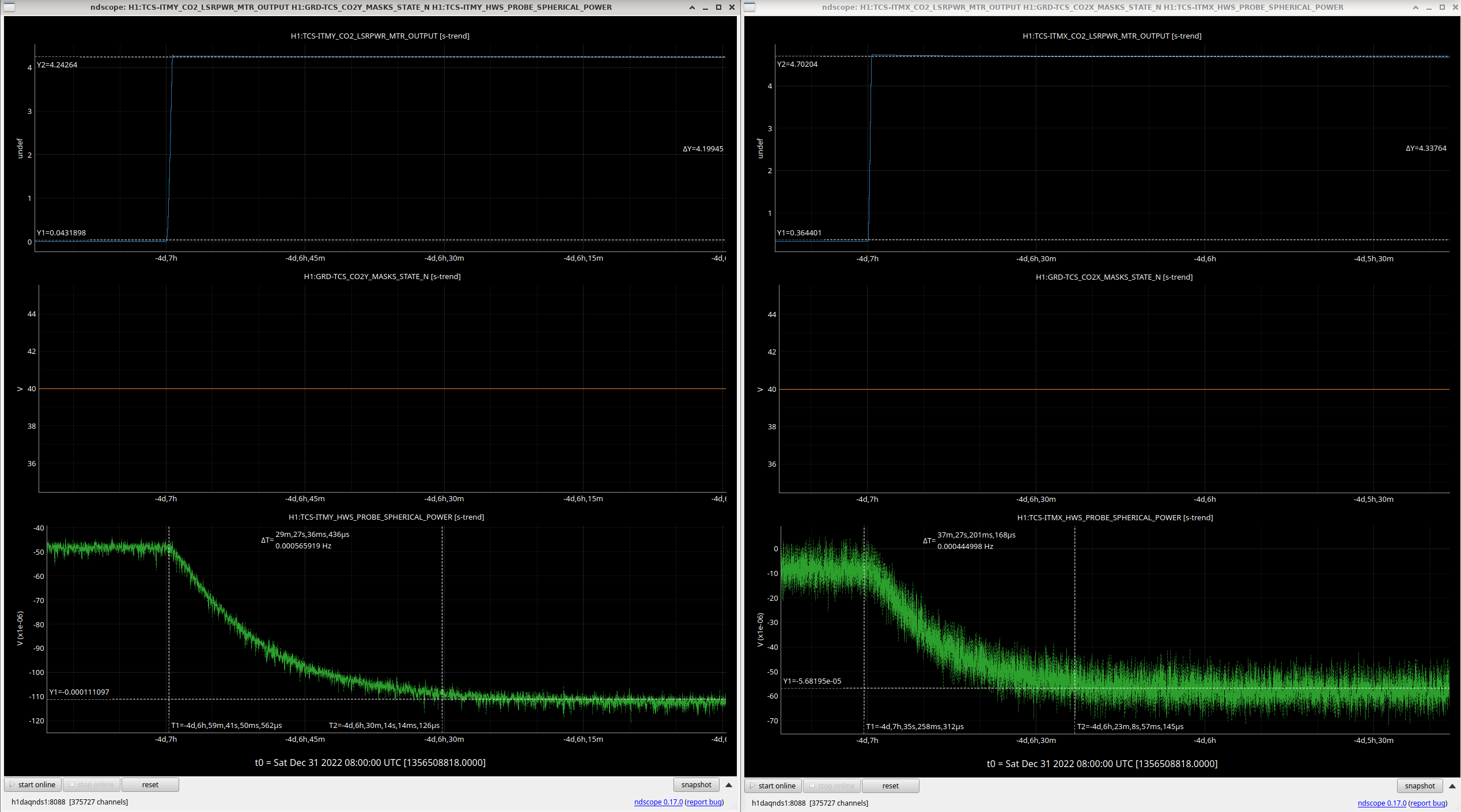
In looking at data from the HWS, the values are divided by 2 to account for double passing (the compensation plates, ITM substrate, and SR3 are all double passed by the HWS beam). These are then reported in micro diopters of spherical power, which is a measure of the change in wavefront curvature.
If we are using these values to calculate the focal length of a lens, we would use: f_new = 1/(1/f_original +spherical power)
If we are talking about a curved mirror, and we want to calculate the radius of curvature we use: Rc_new = 2/(2/Rc_original + spherical power)
| ITMX(uD/W) | ITMY (uD/W) | ||
| Ring heater (substrate lens) | -10uD/W | -10uD/W | 90003 (also close to value Matt's thesis from measurement and model, close to -9.9 uD/W value in finesse). Note that this is per Watt of total ring heater power, not per segment power |
| ETM Ring heater (surface) |
1.63+/- 0.11uD/W (Matt Todd's thesis) 1.53+/- 0.2 uD/W (88148) |
Matt defines the "surface defocus" in his thesis,
Di = 2/Ri , this should be equivalent to spherical power in the equation above. |
|
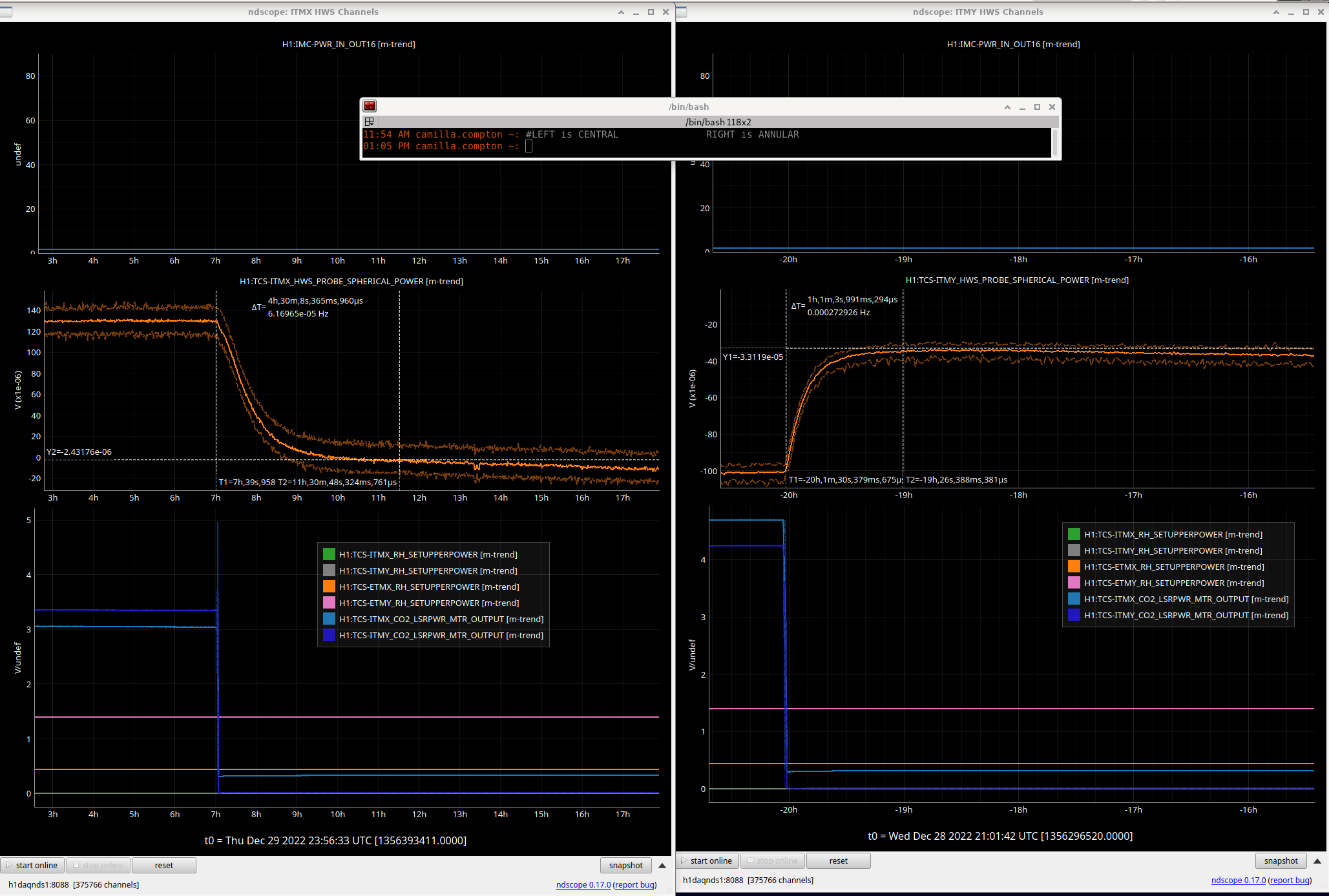
| central CO2 | 23.7uD/W | 26.5uD/W | 89999 |
| annular CO2 | -5.4uD/W | -7.3uD/W | 89999 |
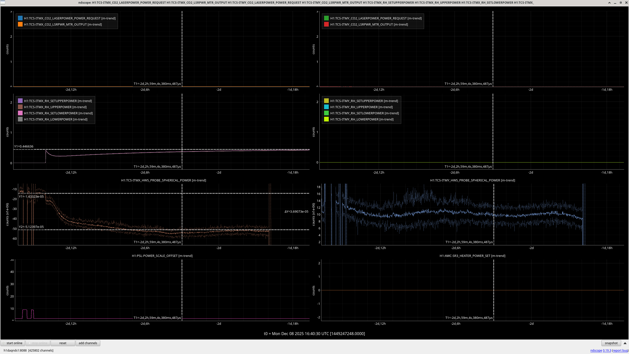
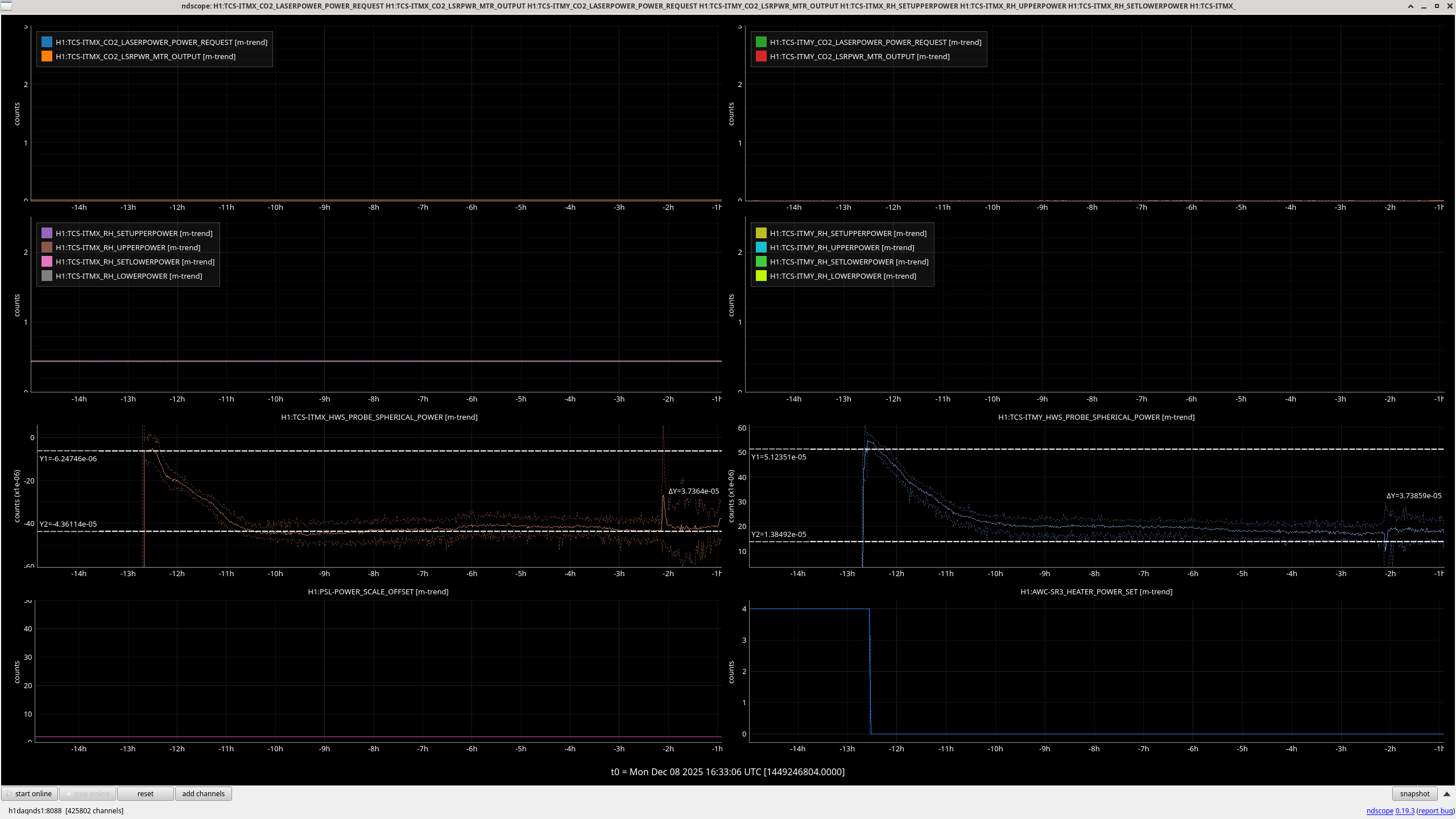
| SR3 heater | 4.75uD/W spherical power, (2.375 µD/W of ROC change) | 88413, agrees with Evan's simulation, T1600095 has 2.9uD/W | |
| OM2 Tsams |
1.75m ROC for "cold" (no heater power, thermistors should both be near room temperature) 2.1m ROC for "hot" (Thermistor 2 temperature 73C) |
ROC data: 65280 Jennie Wright summary of hot and cold ROCs: 84255 |
|


The measured SR3 RoC change coefficient agrees with the value from 2D axisymmetric finite element simulation in which uniform circular irradiation is applied to the central 6″ diameter of the back of SR3. This code exists as a test function
test_back_heat()infinesse-fenicsx. Compare the heater plate design in D1500385. Aidan's Comsol model is T1600096.