FAMIS 31135
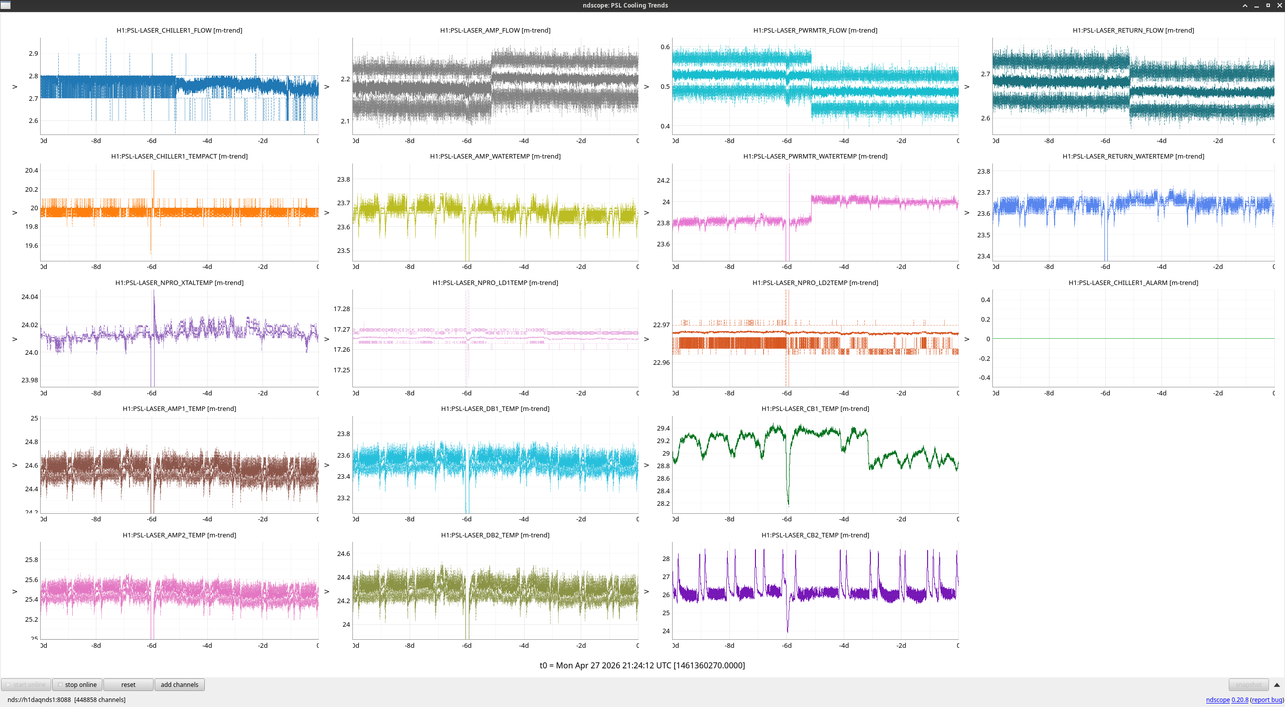
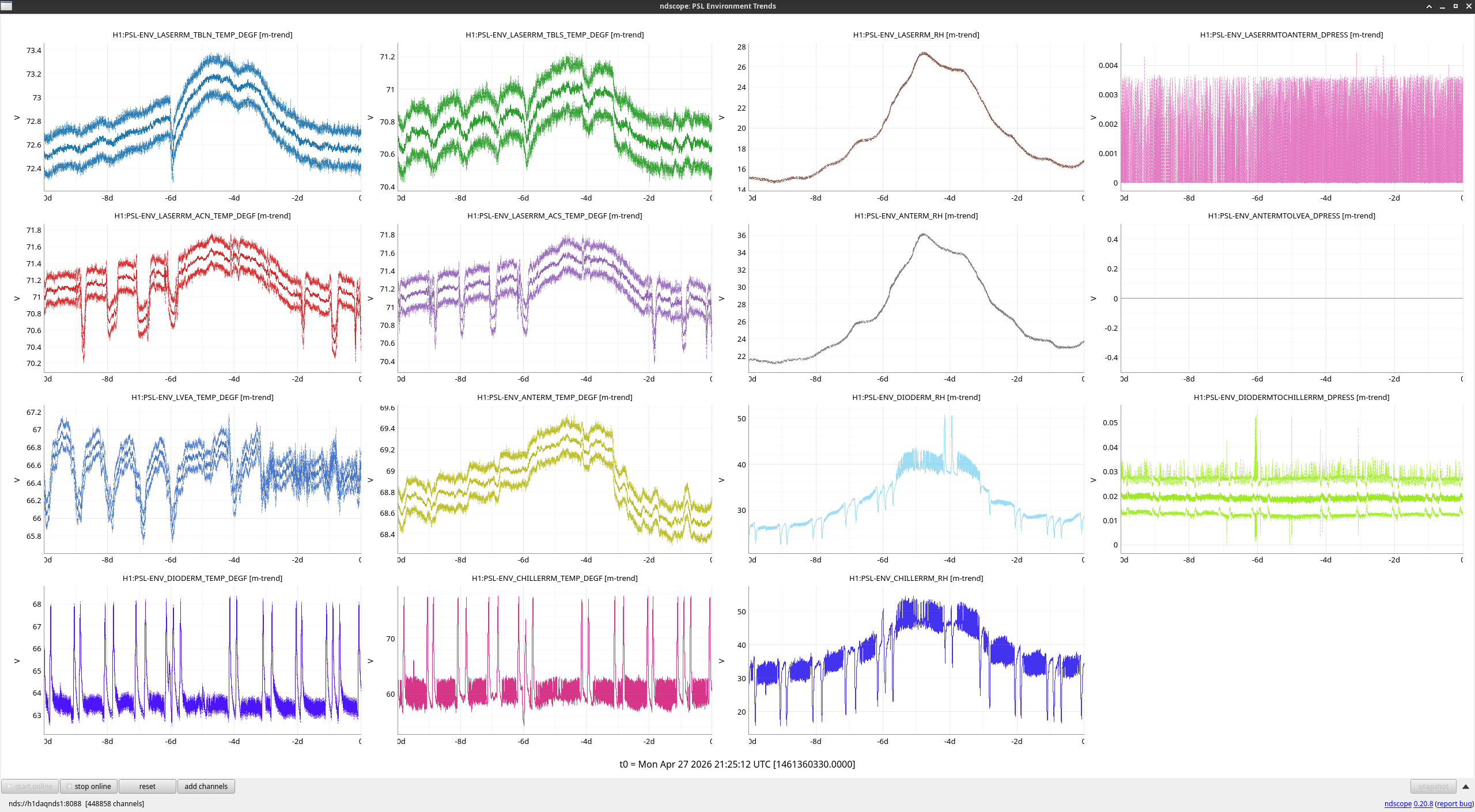
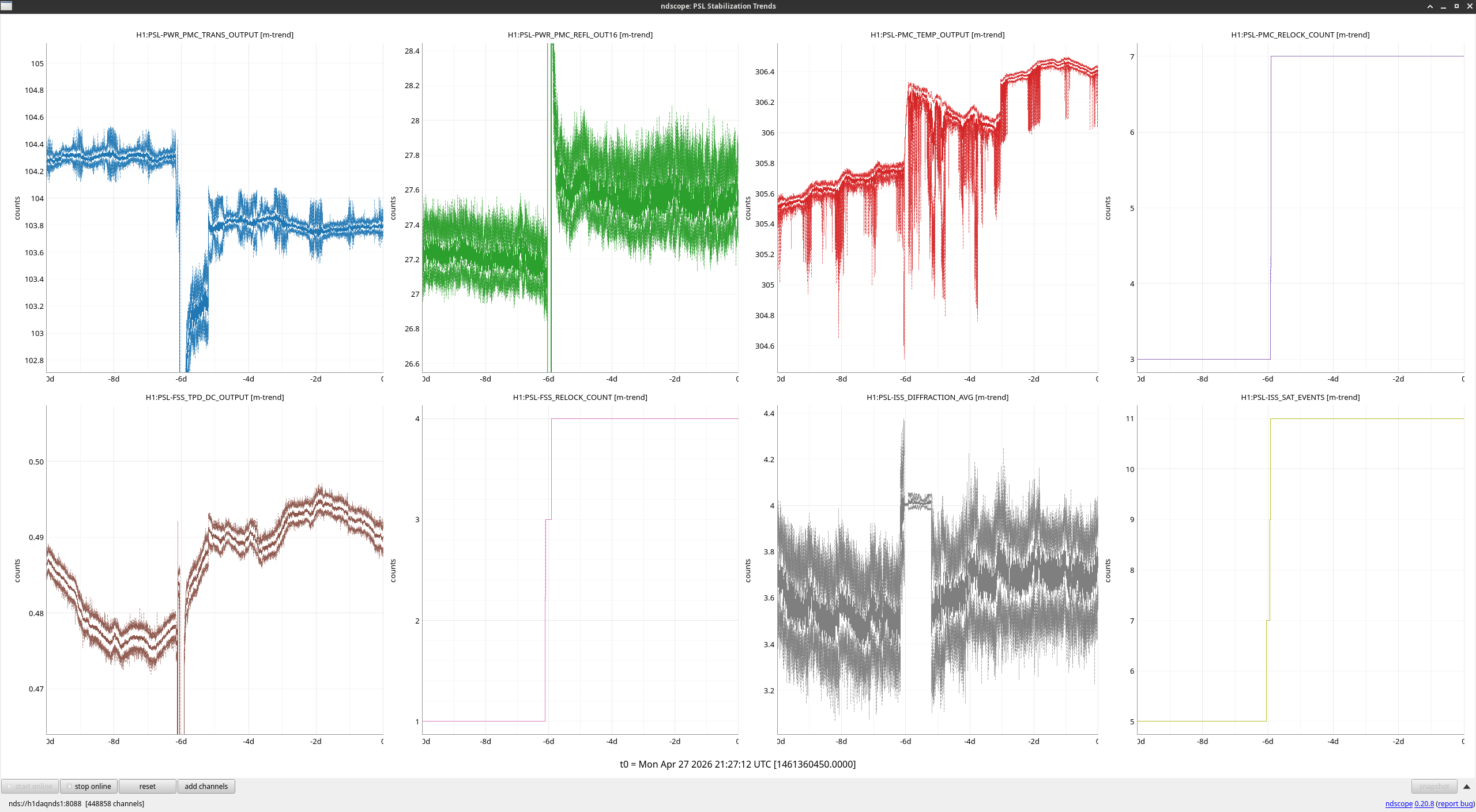
The PSL was offline for a bit last Tuesday for chassis work that took down the interlock (alog89965), but came back up with only a few things being different. Most notably, the PMC is at a slightly different temperature, so the transmitted power is a bit lower while the reflected power is a bit higher.
The BSC2 cartridge was removed from the BSC2 chamber today and placed on the Test Stand in the West Bay (+Y bay). The lift took 3 "test lifts" to make very minor adjustments to the CG prior to lift out of the chamber - on the 4th lift, we were very well balanced so embarked on the flight. Like LLO, the BS had it's "Stay Leg" assemblies and Vibration Absorber Assemblies removed for the flight. This means it was probably lighter than the 2013 time (alog 5689) when we did this which had the weight slightly heavier. The cartridge plus 3-point lift fixture and load cell together all weighed 9380 lbs. It was rotated 90deg Counterclockwise per the procedures and landed on the threaded rod in the test stand with little issue other than careful craning and spotting. All went as expected and according to the procedures E1200433-v3, E1200971-v4 and associated docs. Mitchell, Travis, Tyler, Randy (on crane) all up on the platform Jim and Tony inside of BSC2 Gerardo, Jordan on the eMod as Support TJ on the camera Betsy soaking it all in (support) A pre-lift meeting was held to go over the teams and maneuver details (again) at 9am prior to work starting. Particle counts up at the dome level were all 0,0 before starting. More photos and videos will be posted when those folks have them available. Covers used - A BS/QUAD SUS tube cover up underneath, an ISI cover up on the ISI, the BSC Cartridge sock which encased the whole thing, dropped down to Jim and Tony once the lift was up a couple feet. The bulk of the work was from ~10:30am-1pm. Most of the time before was getting folks in headsets and gear and getting equipment on.
Going over the details during the 9am pre-lift meeting. Congratulations, all, on a smooth operation!
More photos posted at alog 90103.
tagging for photos.
As of 20:05 UTC, the cartridge from BSC2 (including the soon-to-be-decommissioned beamsplitter) has been placed on the test stand in the LVEA West bay. The cartridge was first lifted at 19:15 UTC before making its slow procession across the LVEA via the 5-ton overhead crane. More details and documentation to be posted later.
I've been trying to understand how to make estimates of actuation strength for thermal actuators, and I wanted to make a summary to make this easier in the future. With .
In looking at data from the HWS, the values are divided by 2 to account for double passing (the compensation plates, ITM substrate, and SR3 are all double passed by the HWS beam). These are then reported in micro diopters of spherical power, which is a measure of the change in wavefront curvature.
If we are using these values to calculate the focal length of a lens, we would use: f_new = 1/(1/f_original +spherical power)
If we are talking about a curved mirror, and we want to calculate the radius of curvature we use: Rc_new = 2/(2/Rc_original + spherical power)
| ITMX(uD/W) | ITMY (uD/W) | ||
| Ring heater (substrate lens) | -10uD/W | -10uD/W | 90003 (also close to value Matt's thesis from measurement and model, close to -9.9 uD/W value in finesse). Note that this is per Watt of total ring heater power, not per segment power |
| ETM Ring heater (surface) |
1.63+/- 0.11uD/W (Matt Todd's thesis) 1.53+/- 0.2 uD/W (88148) |
Matt defines the "surface defocus" in his thesis,
Di = 2/Ri , this should be equivalent to spherical power in the equation above. |
|
| central CO2 | 23.7uD/W | 26.5uD/W | 89999 |
| annular CO2 | -5.4uD/W | -7.3uD/W | 89999 |
| SR3 heater | 4.75uD/W spherical power, (2.375 µD/W of ROC change) | 88413, agrees with Evan's simulation, T1600095 has 2.9uD/W | |
| OM2 Tsams |
1.75m ROC for "cold" (no heater power, thermistors should both be near room temperature) 2.1m ROC for "hot" (Thermistor 2 temperature 73C) |
ROC data: 65280 Jennie Wright summary of hot and cold ROCs: 84255 |
|
The measured SR3 RoC change coefficient agrees with the value from 2D axisymmetric finite element simulation in which uniform circular irradiation is applied to the central 6″ diameter of the back of SR3. This code exists as a test function test_back_heat() in finesse-fenicsx. Compare the heater plate design in D1500385. Aidan's Comsol model is T1600096.
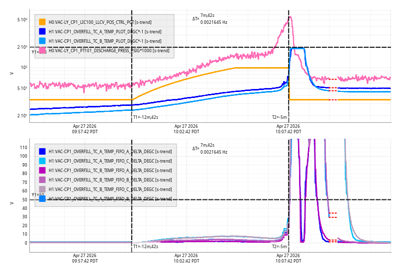
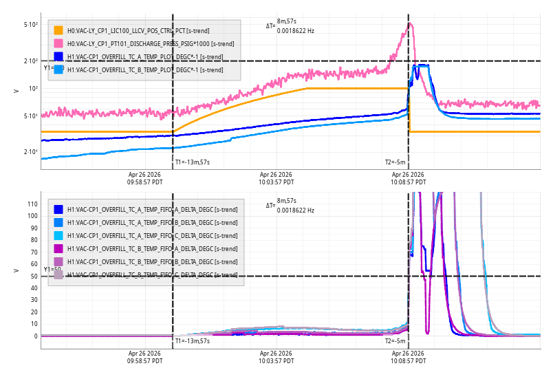
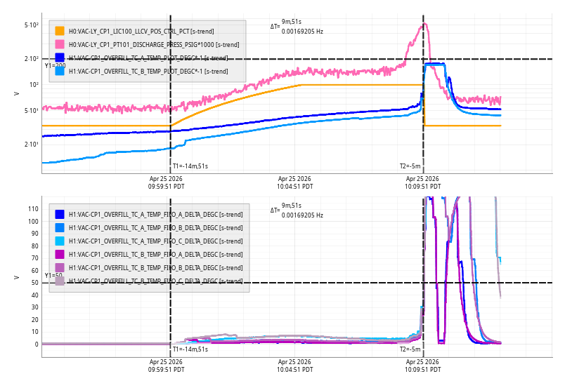
Mon Apr 27 10:07:42 2026 INFO: Fill completed in 7min 39secs
TITLE: 04/27 Day Shift: 1430-2330 UTC (0730-1630 PST), all times posted in UTC
STATE of H1: Planned Engineering
OUTGOING OPERATOR: None
CURRENT ENVIRONMENT:
SEI_ENV state: MAINTENANCE
Wind: 9mph Gusts, 5mph 3min avg
Primary useism: 0.02 μm/s
Secondary useism: 0.16 μm/s
QUICK SUMMARY: The BSC2 (BS) cartridge is planned to be flown out of the chamber and onto the test stand in the LVEA West bay today!
We have some cell phone alarm bypasses in place this week.
EY Chiller supply temp is above nominal, a contractor will work on this during the week.
Fire pumps are running intermittently to supply water for construction. These are only bypassed during construction hours.
Bypass will expire:
Sat May 2 07:05:16 AM PDT 2026
For channel(s):
H0:FMC-EX_CY_H2O_SUP_DEGF
H0:FMC-CS_FIRE_PUMP_1
H0:FMC-CS_FIRE_PUMP_2
Friaday Jim and I installed the lifting pads onto BSC2. Jim also secured disconnected cables, while I assisted Ibrahim with suspension gusset removal.
Sun Apr 26 10:08:57 2026 INFO: Fill completed in 8min 54secs
Sat Apr 25 10:09:51 2026 INFO: Fill completed in 9min 48secs
Fri Apr 24 10:11:05 2026 INFO: Fill completed in 11min 1secs
TITLE: 04/24 Day Shift: 1430-2330 UTC (0730-1630 PST), all times posted in UTC
STATE of H1: Planned Engineering
INCOMING OPERATOR: None
SHIFT SUMMARY:
CDS Frame Write restarts @ 15:21 UTC
Lots BSC2 work was done today.
Beam splitter Stays were removed and in between BSC2 and HAM4. Pictures of the Beam Splitter cover and more details can be found here: alog link.
The Beam splitter cartridge is closer than ever to fly out of the BSC2 Chamber.
LOG:
| Start Time | System | Name | Location | Lazer_Haz | Task | Time End |
|---|---|---|---|---|---|---|
| 14:56 | FAC | Kim & Nellie | LVEA | N | Technical Cleaning & resupply Nellie out first | 15:49 |
| 15:45 | CDS | Jonathan | Remote | N | FW restarts. | 15:50 |
| 16:11 | FAC | TJ, Randy | LVEA | N | Moving IOT2 table. | 16:35 |
| 16:24 | IAS | Jason & Ryan C | LVEA West bay | N | Faro surveying. | 19:24 |
| 16:33 | EE | Marc | LVEA | N | Pulling sat amps | 17:13 |
| 16:39 | FAC | Randy | LVEA | N | Working on MEGA CleanRoom | 21:32 |
| 16:53 | SEI | Jim | CER | N | Checking AA chassis for inputs | 17:08 |
| 19:24 | SUS | Ibriham & Betsy | LVEA BSC2 | N | Putting a sheild around the BS. | 20:45 |
| 19:31 | SPI | Jeff | Optics lab | N | Dropping part off | 19:31 |
| 20:21 | SEI | Jim | LVEA BSC2 | N | Helping prep for flying a Beam splitter | 22:42 |
| 20:33 | SUS | Mitch | LVEA | N | Helping Jim/Betsy | 21:32 |
| 20:43 | IAS | Jason & Ryan C | LVEA West bay | N | Faro surveying | 22:44 |
| 21:32 | SUS | Ibrahim | LVEA BSC2 | N | Takeing BS stays | 22:42 |
| 21:58 | BHSS | Keita & Disha & Elenna | Optics lab | yes? | Working on Manta Ray | 22:44 |
Ibrahim, Jim, Mitchell
Mitchell and I removed the BS stays from the beamsplitter and placed them in the tube between BSC2 and HAM4. Then, Mitchell and I put the cover over the BS.
Jim and Mitchell were working on removing and bundling SEI cables from inside BSC2 for storage by ISI. Jim (on ISI) and I (in BSC2) then removed cable clamps from the bottom of the ISI/ceiling of BSC2.
Picture provided.
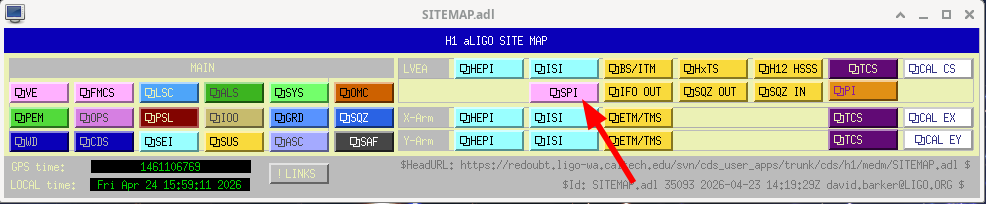
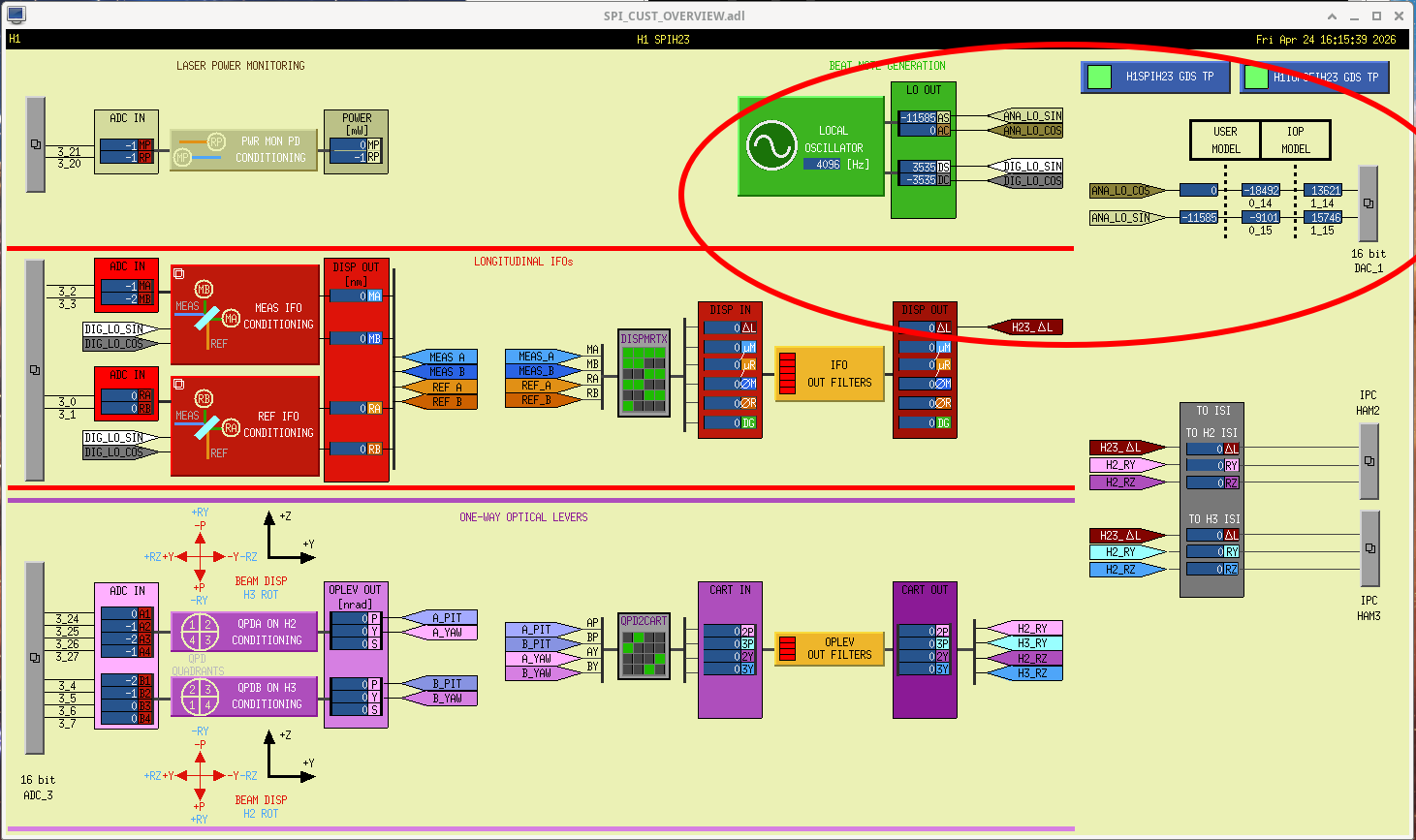
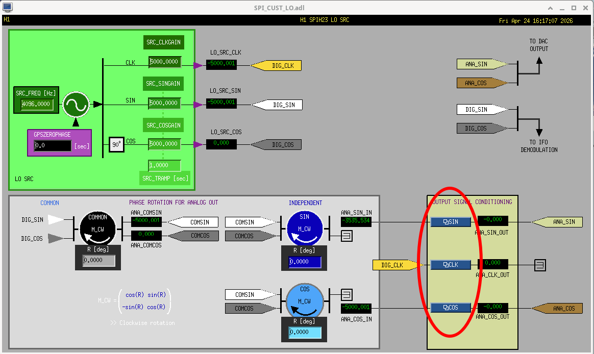
J. Kissel After the install of front-end software (LHO:89777 and LHO:89919) the next step for SPI is MEDM screens -- the UI/UX for the SPI L interferometers and PY one-way optical levers. Here, I post screenshots and corresponding userapps svn file and location. Sub-screens and their future purpose will come in the comments, but make sure to also check out G2402138. In the main entry, I show off the new place that SPI lives on the LHO sitemap and the overview screen. The overview screen, and all subordinate screens use a marco file, which I also attach. All of these files are, of course, properly version controlled in the userapps SVN, here: OVERVIEW SCREEN ${USERAPPS}/spi/common/medm/ SPI_CUST_OVERVIEW.adl rev 35102 MACRO FILE ${USERAPPS}/spi/h1/medm/ h1spih23_overview_macro.txt rev 35106
POWER MONITORING
These cover the on-board power monitor SPDs. Eventually, we'll use these filter banks to calibrate the PDs into [mW] as it lands on the ISIK breadboard.
${USERAPPS}/spi/common/medm/SPI_CUST_FBR_PWRIN.adl rev 35102
LOCAL OSCILLATOR The SPI's longitudinal IFO that measures the differential displacement in the main IFO's X direction release on heterodyne interferometry, with the interference between two beams modulated at 80 MHz and (80 MHz- 4096 Hz) = 79995904 Hz, which creates a beat note at 4096 [Hz]. 80 MHz comes from the site's RF distribution system of 80 MHz. The 4096 Hz is initially digitally generated via CDS, and a copy of that is sent out via DAC to be subtracted from 80 MHz with our homegrown single-sideband mixer, a.k.a "double mixer" (D2400315). This is the screen that controls the parameters of the cds oscillator, as well as some phase rotators and filterbanks to condition the digital LO into an analog signal for the DAC. Nominally, the cds oscillator clock emits a 1 [count] amplitude wave, and the CLKGAIN, SINGAIN and COSGAIN parameters are set arbitrarily high, since its use as the LO for digital demodulation is usually entire internal to CDS. However, because this LO goes somewhere into real electronics, I've set the calibration of the signal condition filters such that the CLK, SIN, and COS gain are in units of [mV/ct] -- and I've set the LO amplitude at 5000 [mV] = 5 [V], mid-range of the DAC. Since we don't yet know the right phasing, all the phase rotators are current set to 0 [deg]. ${USERAPPS}spi/common/medm/SPI_CUST_LO.adl rev 35103
INTERFEROMETERS
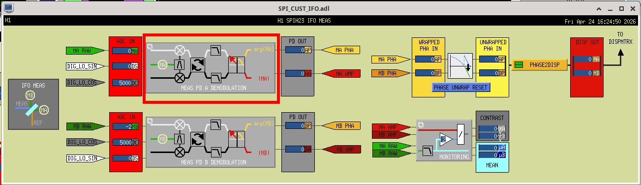
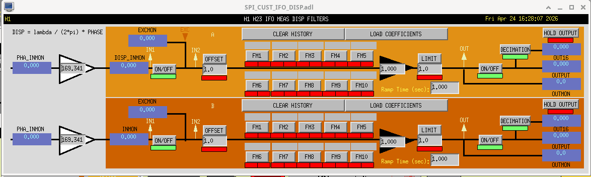
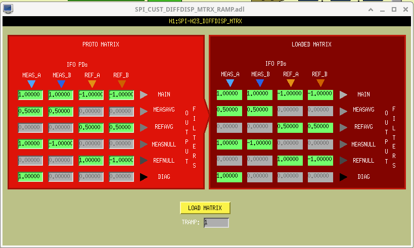
Here're the screens (less commissioned) that cover the digital demodulation and conversion to differential displacement.
${USERAPPS}spi/common/medm
SPI_CUST_IFO.adl
SPI_CUST_IFO_DEMOD.adl
SPI_CUST_IFO_DISP.adl
SPI_CUST_DIFFDISP_MTRX_RAMP.adl
SPI_CUST_DIFFDISP.adl
all commited to rev 35102
ONE-WAY OPTICAL LEVERS
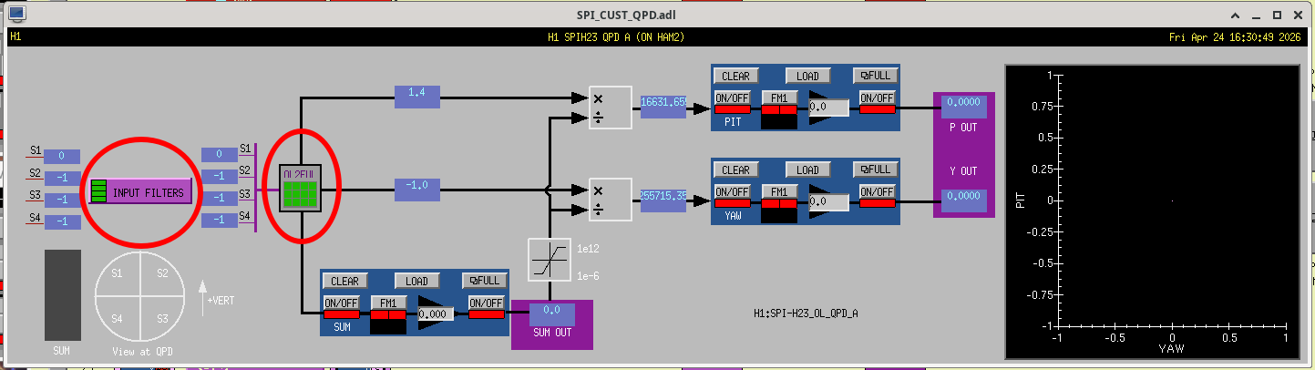
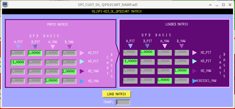
Here's the signal chain for the one-way optical levers. There's a good bit of confusing basis changing happening given
- the orientation of the QPD segments w.r.t. to vertical being different on HAM2's ISIJ QPDA and HAM3's ISIK QPDB,
- The usual conversion from QPD segments to pitch and yaw, as the beam flies, then
- Converting from beam pitch and yaw to ISI rotation, given that the HAM2 QPDA measuring HAM3 rotation is on the "front" +X side of HAM2, and the HAM3 QPDB measuring the HAM2 rotation is on the "back" -X side of HAM3.
So I had to make custom SPI screens (rather than use the standard ASC QPD screen) that hopefully clears all this up. Also, the QPD2CART matrix is a ramping matrix, and I've never liked the auto-generated MEDM screen for this, so I pioneered a new one that I think has a better user interface.
${USERAPPS}/spi/common/medm/
SPI_CUST_QPD.adl
SPI_CUST_QPD_MTRX.adl
SPI_CUST_OL_QPD2CART_RAMP.adl
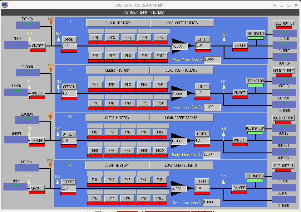
SPI_CUST_OL_ISIOUTF.adl
all at rev 35103.
M. Todd, S. Muusse, C. Compton, S. Dwyer
I wanted to get another measurement of what the HWS think the coupling factor is for thermal lens from ring heater power.
The HWS were not on, so after filling out a work permit Camilla and I went out and turned on the HWS SLEDs. Then we restarted the HWS codes in the individual computers. We also asked Jim to take ITMY ISI to fully isolated.
After waiting about 25 minutes for the HWS to get a baseline reading we turned up both ITMY and ITMX ring heaters by 4W (2W/segment). The HWS will track the defocus and I will compare with my models tomorrow morning. I wanted to do both ITM ring heaters to get a self-consistent measurement.
We also plan on doing single bounce OMC scans tomorrow morning with the ITMs being sufficiently thermalized after the RH turn on. This should give us another lens (punny pun here) to look at the thermalization business.
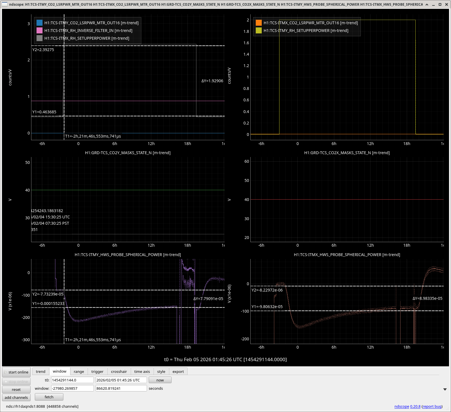
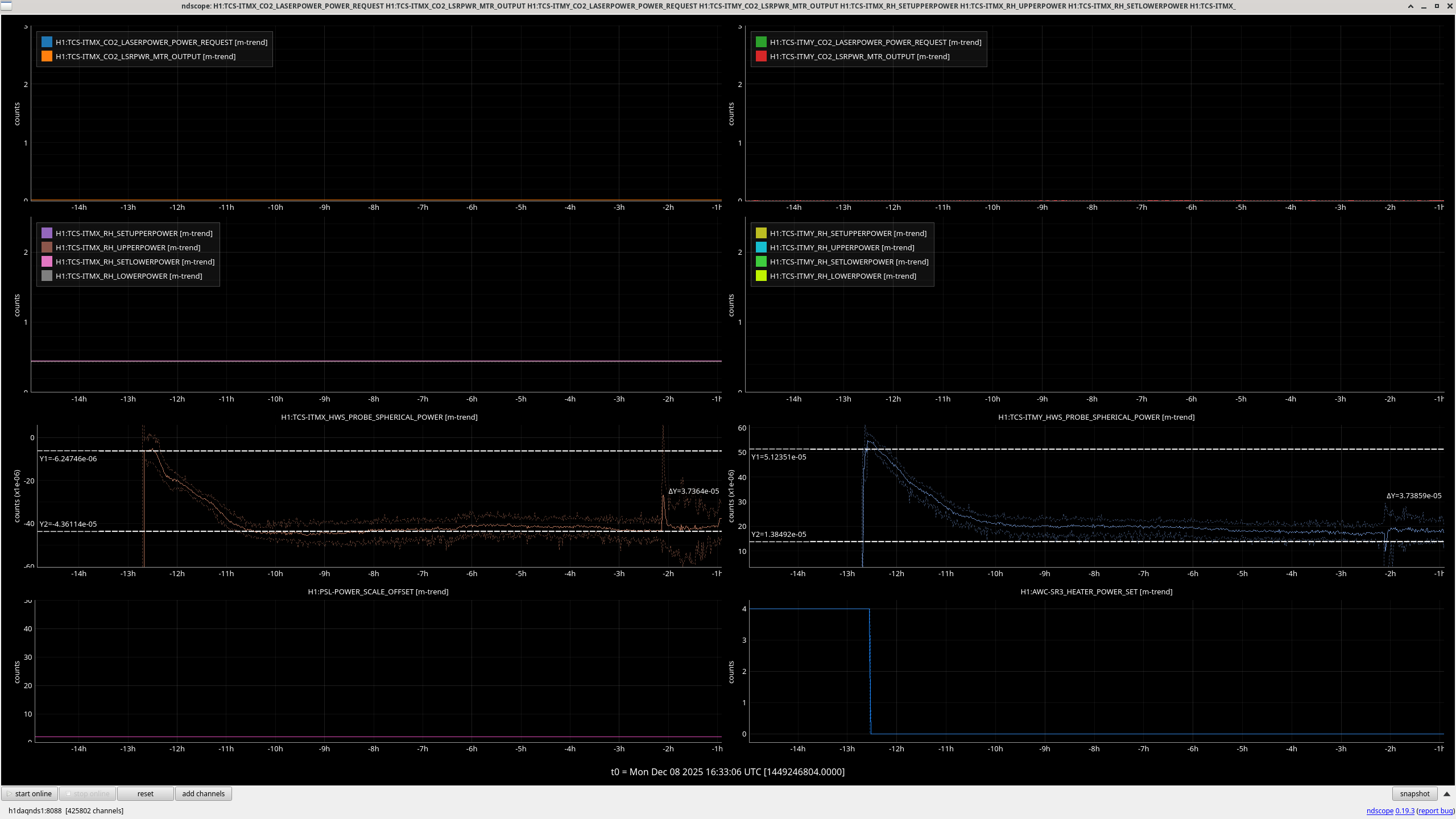
Here is a screenshot of this test. For ITMX this shows -78 uD of spherical power for 4W of total ring heater power. This means -9.75uD/W of defocus of the substrate lens.
For ITMY this is -82uD of spherical power for 4W, which is -10.25uD/W of defocus. This agrees reasonably well with the -9.9uD/W that is used in finesse.
M. Todd, S. Dwyer, J. Driggers
| Measurement | Value [uD / W] | Notes |
| Ring Heater Coupling to Substrate Lens | -21.0 +/- 0.3 | relative to modeled coupling, 79 +/- 1 % efficiency compared to predicted 75-80% efficiency from arm cavity measurements. Modeled couplings assuming 100% efficiency report around -26.5 uD/W. |
| SR3 Heater Coupling to Substrate Lens |
ITMX HWS: 4.7 +/- 0.2 ITMY HWS: 4.6 +/- 0.1 |
The ITMX HWS seems to be noisier than ITMY, but give very similar mean estimates. The estimate from Gouy phase measurements is around 5.0 uD/W. |
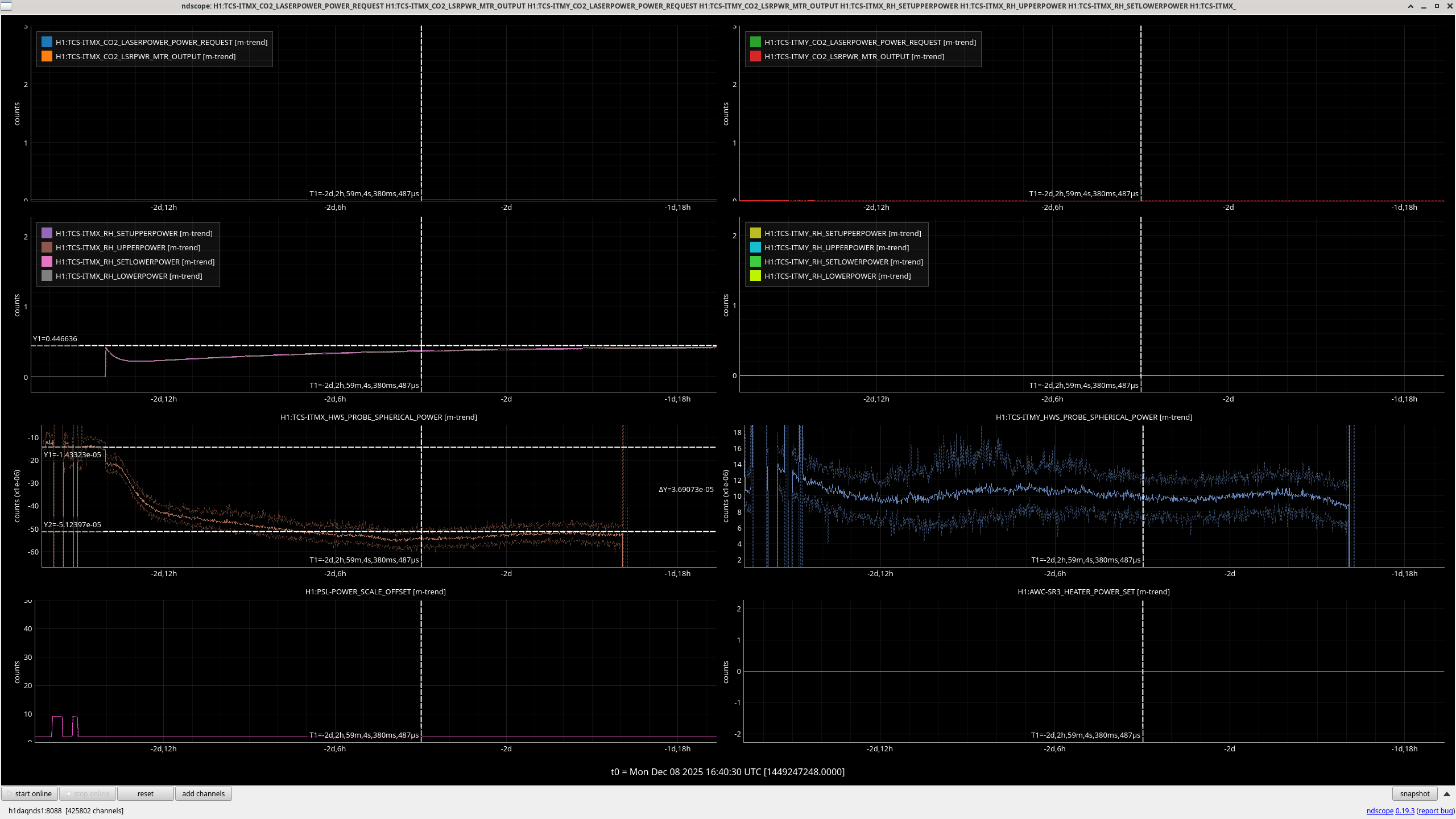
We turned on inverse ring heater filters to speed up the heating for those (using nominal values for the settings). Because of the weekend mayhem with the earthquakes we did not get a SUPER long HWS transient measuring the full response, but we could get a pretty good estimate of the ring heater effect on the substrate thermal lens without any other heating in the measurement. This is good to compare to modeled values that we have.
I also turned on SR3 heater on Sunday to get estimates of the coupling of SR3 heating to the defocus of SR3. To do this, Jenne helped me untrip a lot of the SU watchdogs for the relevant optics to the HWS. About 3 hours after the SR3 was turned on the watchdogs must have tripped again and misaligned the optics. But fortunately we got the cooldown data for this as well and it's all pretty consistent. These measurement suggest a 4.7 uD/W coupling for SR3 heating, which is very similar to modeled coupling from Gouy phase measurements at different SR3 heater powers.
Overall, while these measurements provide more pieces to the puzzle, they make previous analyses a bit more confusing, requiring some more thought (as usual).
In the estimates for SR3 heater above, Matt is using the requested power on SR3 to do the estimation, which is higher than the reported power.
For both the October 2019 Gouy phase measurement and for the December 2025, the SR3 requested power was 4 W while the readback power was 3.2W.
I used the same cool down time that Matt used above, reading 38uD change in spherical power from the X HWS and 34.5uD, if we use the reported power change of 3.2W we get 5.9 uD/W reported by HWS X and 5.4uD/W reported by HWS Y.
When Matt quotes uD/W for the ring heaters above, he is talking about total ring heater power, while the ndscope screenshot he attaches shows per segment power.
So he arrives at his 21uD/W = (change of 36uD/(2segments*0.44Watts per segment))/(factor of 2 for going from spherical power to defocus).
This is about twice the actuation strength measured in 89038, which agrees with the number and the simulation in Matt's thesis, and the value of -9.9uD/W used in finesse.
For a similar measurement of the CO2 heating, see 89999