ryan.short@LIGO.ORG - posted 16:30, Wednesday 22 April 2026 (89979)
Ops Day Shift Summary
TITLE: 04/22 Day Shift: 1430-2330 UTC (0730-1630 PST), all times posted in UTC
STATE of H1: Planned Engineering
INCOMING OPERATOR: None
SHIFT SUMMARY: More progress towards preparing to remove the BSC2 cartridge, both in-chamber and out, which is now slated to happen on Monday.
- Walking platforms around the BSC2 ISI were installed: alog89977
- BS OpLev positioning was determined to be good: alog89978
- IOT2L was de-cabled to prepare for its move away from the HAM2 +Y door: alog89975
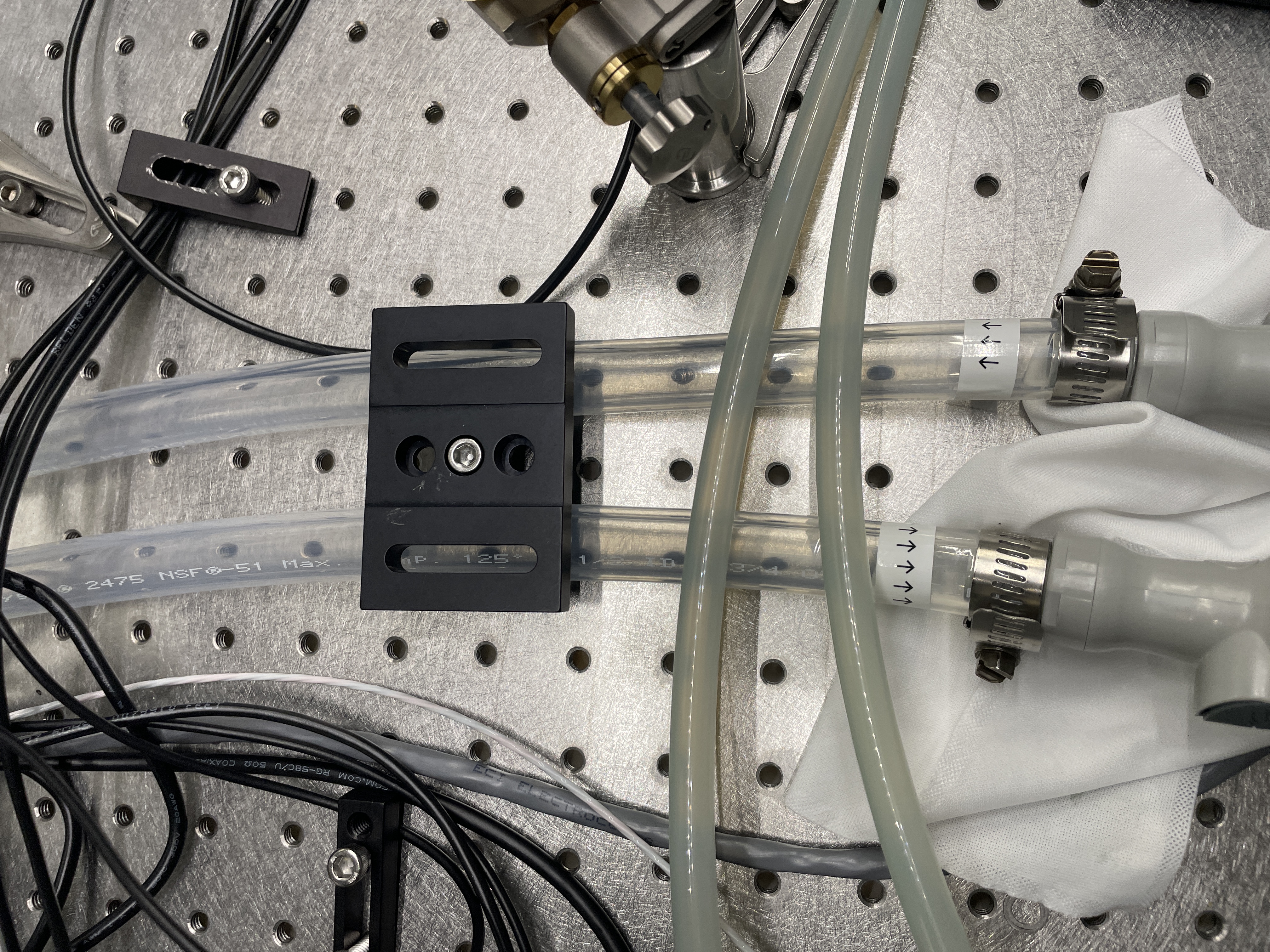
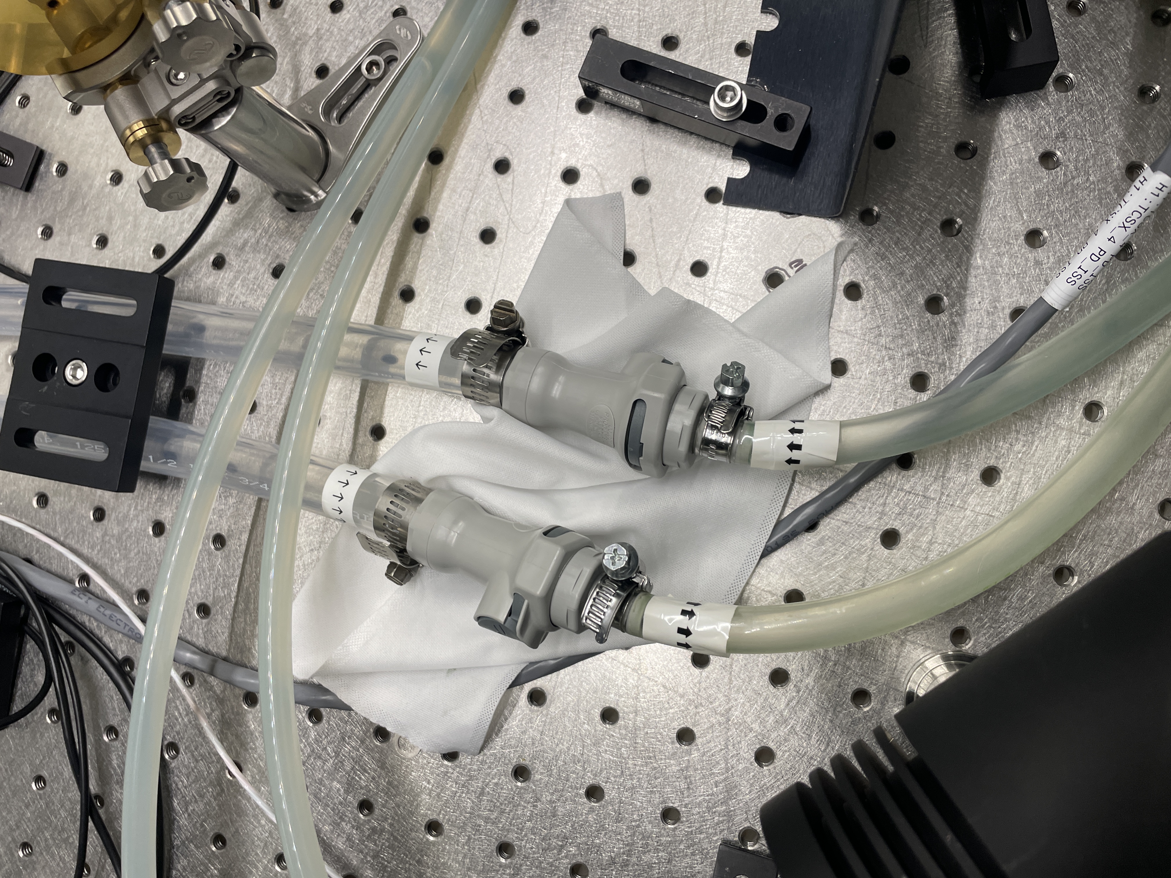
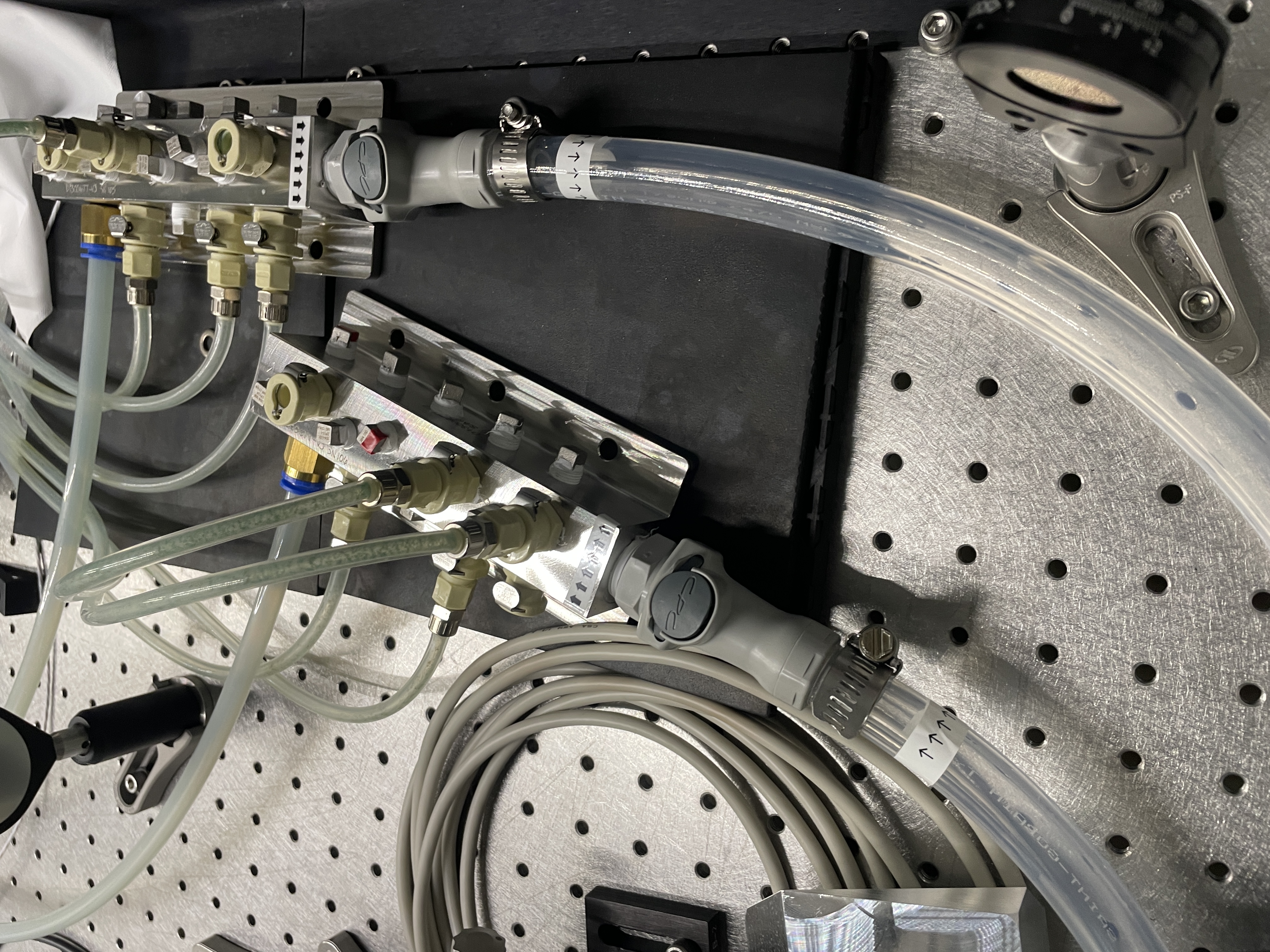
- More water lines on the TCSX table were replaced: alog89976
LOG:
| Start Time | System | Name | Location | Lazer_Haz | Task | Time End |
|---|---|---|---|---|---|---|
| 14:39 | FAC | Kim, Nellie | LVEA | - | Technical cleaning | 16:00 |
| 14:39 | FAC | Randy | LVEA | - | Craning walk platforms at E-mod | 15:36 |
| 15:29 | SUS | Betsy | LVEA | - | Staging for BSC2 | 16:26 |
| 15:46 | SUS | Ibrahim | LVEA | - | Staging for BSC2 | 16:26 |
| 15:48 | EE | Fil | LVEA | - | De-cabling IOT2L | 16:51 |
| 16:00 | FAC | Nellie | EY | - | Technical cleaning | 16:47 |
| 16:07 | TCS | Camilla, TJ | LVEA | - | CO2X table water pipe swap | 16:58 |
| 16:08 | FAC | Kim | MX | - | Technical cleaning | 16:45 |
| 16:52 | EE | Fil | MER | - | HAM6 SUS cabling | 19:37 |
| 17:09 | AOS | Jennie, Tony | LVEA | - | Scouting IOT1 table position | 17:15 |
| 17:12 | EE | Marc | LVEA | - | Grabbing a chassis | 17:20 |
| 17:25 | SUS | Ibrahim, Betsy, Oli | LVEA | - | Inspecting BS and OpLev in-chamber | 18:57 |
| 18:14 | TCS | TJ, Camilla | LVEA | - | CO2X table water pipe swap | 19:44 |
| 18:26 | CAL | Tony | EY | - | Checking PCal interlock | 18:50 |
| 18:31 | SUS | Mitchell | LVEA | - | Dropping off parts | 18:52 |
| 18:33 | FAC | Randy | LVEA | - | Walkabout | 18:57 |
| 19:50 | FAC | Randy, Mitch, Travis | LVEA | - | Installing BSC2 walk platforms (Travis out @ 20:47, Mitch out @ 21:38) | 21:50 |
| 20:04 | FAC | Tyler | EX | - | Checking chiller | 20:51 |
| 20:33 | AOS | Betsy | LVEA | - | Staging for BSC2 | 21:12 |
| 20:50 | AOS | Ibrahim | LVEA | - | Staging for BSC2 | 21:50 |
| 21:13 | ISC | Camilla, Tony | LVEA | - | Rolling up IOT1 | 21:46 |
| 21:22 | SUS | Jason | LVEA | - | Checking BS OpLev pointing | 22:11 |
| 21:32 | SUS | Betsy | LVEA | - | Checking BS OpLev pointing, other checks | 22:29 |
| 21:41 | ISC | Jennie, Madi | LVEA | - | Rolling up IOT1 | 21:46 |
| 22:59 | EE | Marc | LVEA | - | Installing chassis | 23:30 |
Images attached to this report