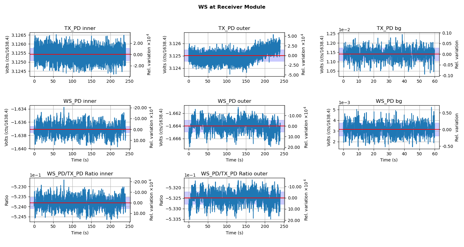
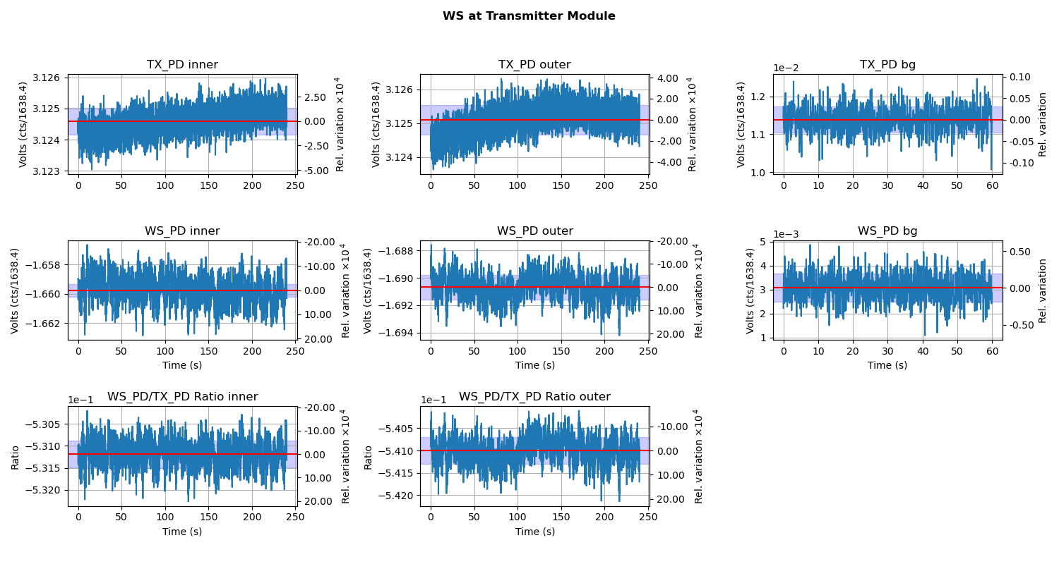
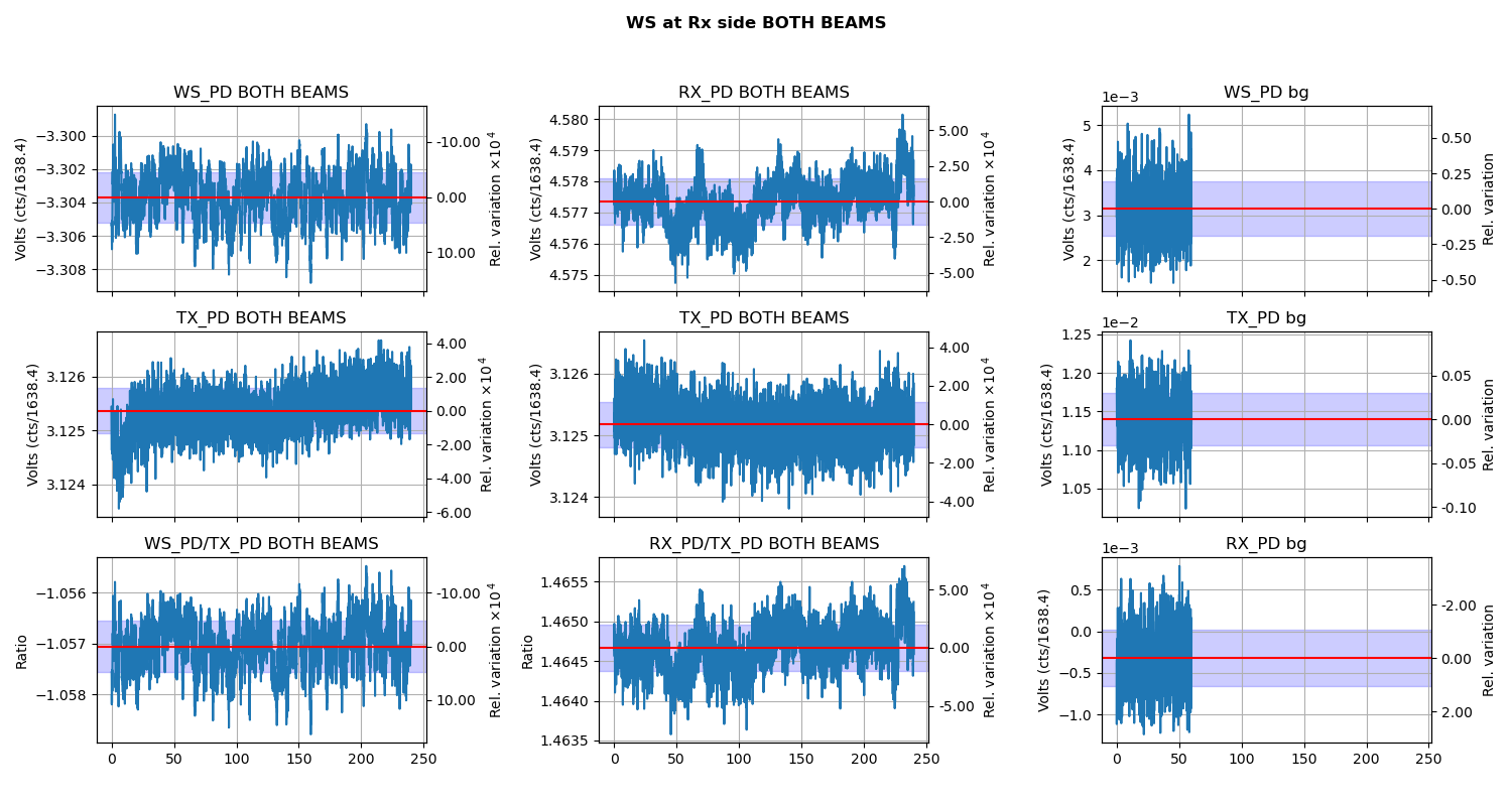
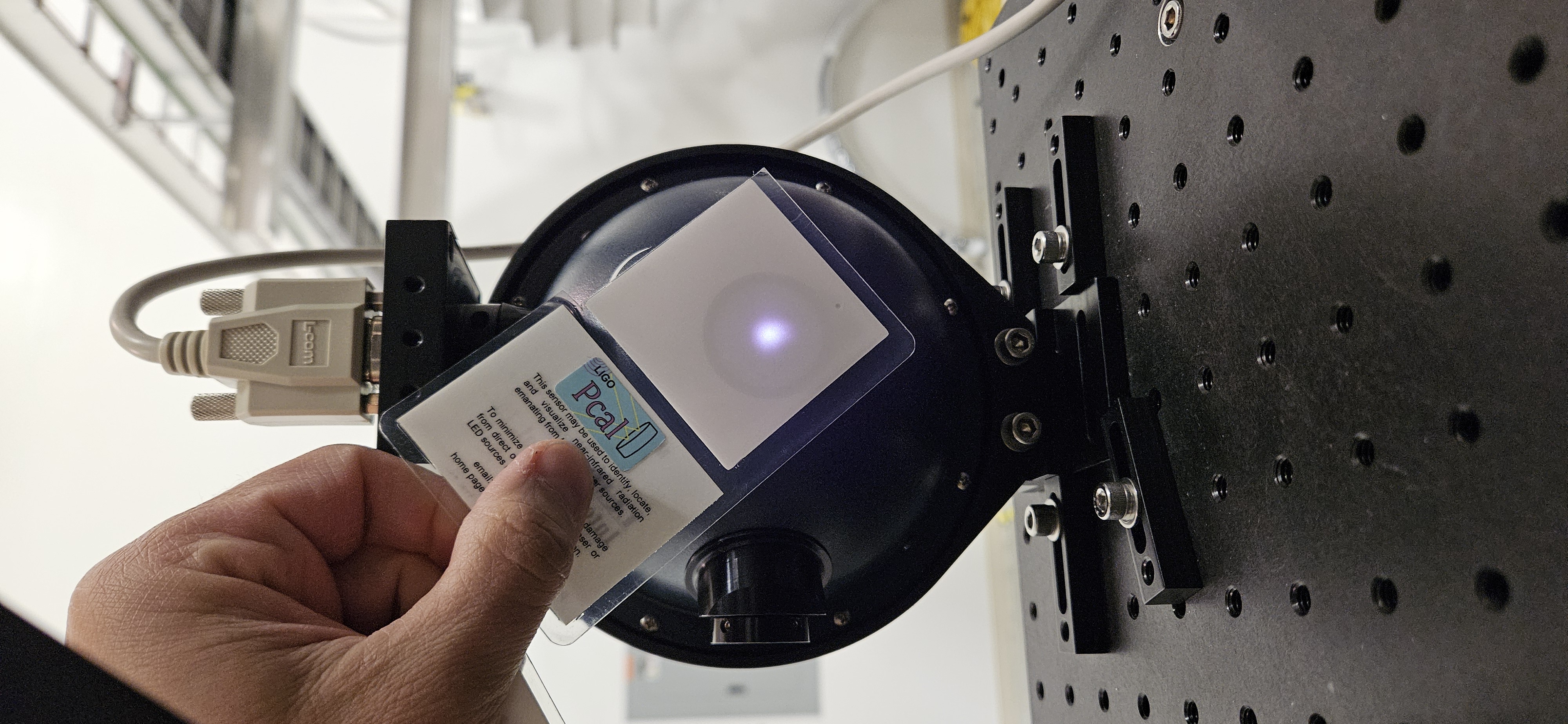
Dripta and I went to EY with PS4 to do a PCAL ES measurement. We followed the T1500062-v21 Procedure but there were changes to the scripts we were using to do the analysis for this measurement.
Obligitory before beam spot.
python3 generate_measurement_data.py --WS PS4 --date 2026-04-02
Reading in config file from python file in scripts
../../../Common/O4PSparams.yaml
PS4 rho, kappa, u_rel on 2026-04-02 corrected to ES temperature 299.9 K :
-4.7013350503199405 -0.0002694340454223 0.0007506545774987483
Copying the scripts into tD directory...
Connected to h1daqnds1
martel run
reading data at start_time: 1459616830
reading data at start_time: 1459617300
reading data at start_time: 1459617635
reading data at start_time: 1459618001
reading data at start_time: 1459618370
reading data at start_time: 1459618700
reading data at start_time: 1459619030
reading data at start_time: 1459619580
reading data at start_time: 1459619930
Ratios: -0.5341166097396405 -0.5439653195648569
writing nds2 data to files
finishing writing
Background Values:
bg1 = 18.656956; Background of TX when WS is at TX
bg2 = 5.029697; Background of WS when WS is at TX
bg3 = 18.678297; Background of TX when WS is at RX
bg4 = 5.152238; Background of WS when WS is at RX
bg5 = 18.675415; Background of TX
bg6 = -0.527308; Background of RX
The uncertainty reported below are Relative Standard Deviation in percent
Intermediate Ratios
RatioWS_TX_it = -0.534117;
RatioWS_TX_ot = -0.543965;
RatioWS_TX_ir = -0.526729;
RatioWS_TX_or = -0.535441;
RatioWS_TX_it_unc = 0.057495;
RatioWS_TX_ot_unc = 0.055038;
RatioWS_TX_ir_unc = 0.052784;
RatioWS_TX_or_unc = 0.054928;
Optical Efficiency
OE_Inner_beam = 0.986428;
OE_Outer_beam = 0.984304;
Weighted_Optical_Efficiency = 0.985366;
OE_Inner_beam_unc = 0.042212;
OE_Outer_beam_unc = 0.043766;
Weighted_Optical_Efficiency_unc = 0.060806;
Martel Voltage fit:
Gradient = 1637.917034;
Intercept = 0.063908;
Power Imbalance = 0.981895;
Endstation Power sensors to WS ratios::
Ratio_WS_TX = -0.927573;
Ratio_WS_RX = -1.384310;
Ratio_WS_TX_unc = 0.046237;
Ratio_WS_RX_unc = 0.042014;
=============================================================
============= Values for Force Coefficients =================
=============================================================
Key Pcal Values :
GS = -5.135100; Gold Standard Value in (V/W)
WS = -4.701335; Working Standard Value
costheta = 0.988362; Angle of incidence
c = 299792458.000000; Speed of Light
End Station Values :
TXWS = -0.927573; Tx to WS Rel responsivity (V/V)
sigma_TXWS = 0.000429; Uncertainity of Tx to WS Rel responsivity (V/V)
RXWS = -1.384310; Rx to WS Rel responsivity (V/V)
sigma_RXWS = 0.000582; Uncertainity of Rx to WS Rel responsivity (V/V)
e = 0.985366; Optical Efficiency
sigma_e = 0.000599; Uncertainity in Optical Efficiency
Martel Voltage fit :
Martel_gradient = 1637.917034; Martel to output channel (C/V)
Martel_intercept = 0.063908; Intercept of fit of Martel to output (C/V)
Power Loss Apportion :
beta = 0.998844; Ratio between input and output (Beta)
E_T = 0.992082; TX Optical efficiency
sigma_E_T = 0.000302; Uncertainity in TX Optical efficiency
E_R = 0.993230; RX Optical Efficiency
sigma_E_R = 0.000302; Uncertainity in RX Optical efficiency
Force Coefficients :
FC_TxPD = 9.158224e-13; TxPD Force Coefficient
FC_RxPD = 6.227715e-13; RxPD Force Coefficient
sigma_FC_TxPD = 4.284257e-24; TxPD Force Coefficient
sigma_FC_RxPD = 2.800786e-24; RxPD Force Coefficient
data written ... to /ligo/gitcommon/Calibration/pcal/O4/ES/measurements/LHO_EndY/tD20260407
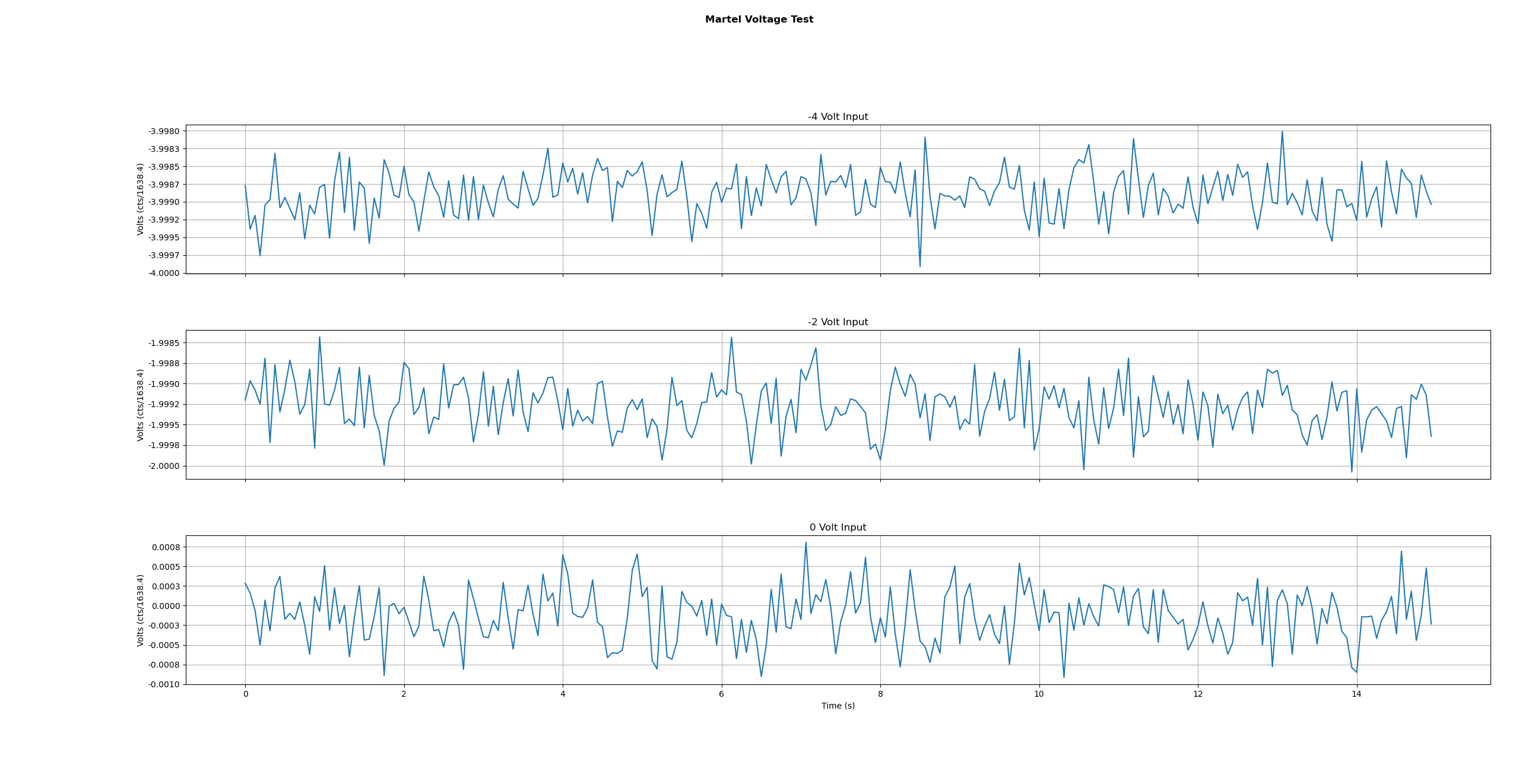
Martel_Voltage_test.png
WS_at_RX.png
WS_at_TX.png
WS_at_RX_BOTH_BEAMS.png
Final Report is here: LHO_EndY_PD_ReportV6.pdf
Final beamspot .
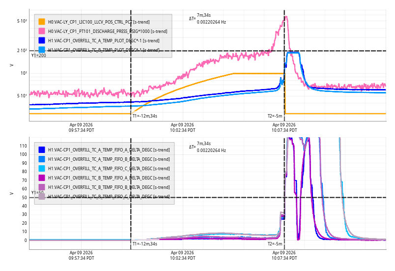
Thu Apr 09 10:07:34 2026 INFO: Fill completed in 7min 31secs
WP 13154
a-Plus O5 SUS HAM5 (sush5) System Wiring Diagrams - D2300380
aLIGO SUS HAM 5-6 System Wiring Diagrams - D1002740
SUS-C7/ SUS-C8
Two HAM-A coil drivers were installed in the SUS-C7 rack, part of LO3. We decided to use the existing OMC cables for the new OFI. Cables are going to correct CER and field rack. OMC is being moved to the MER. Once HAM6 is vented the OM1/OM2/OM3 electronics and cabling will be removed.
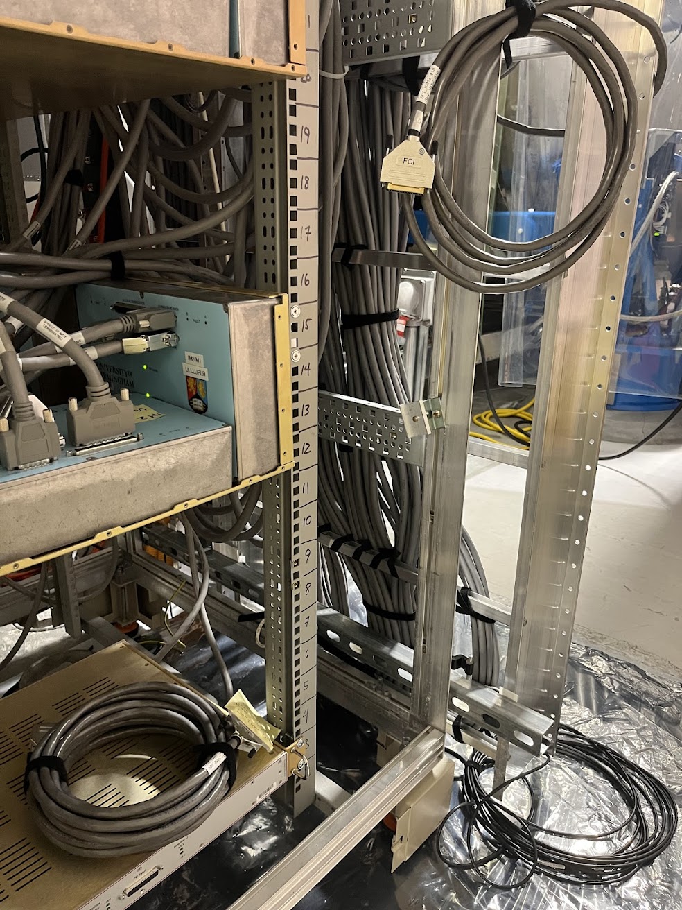
SEI-C1
Started clean-up of the SEI racks. Removed a HAM ISI Interface Chassis from SEI-C1. This was part of the HAM1 L4C testing back in 2018. Plan is to remove the STS distribution electronics. See alog 89835 for testing of sending signals over IPC.
ISC-C3
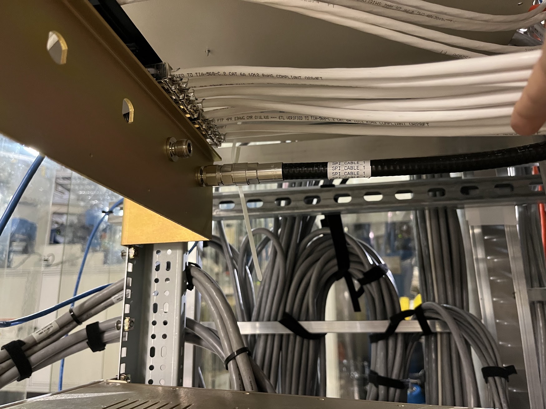
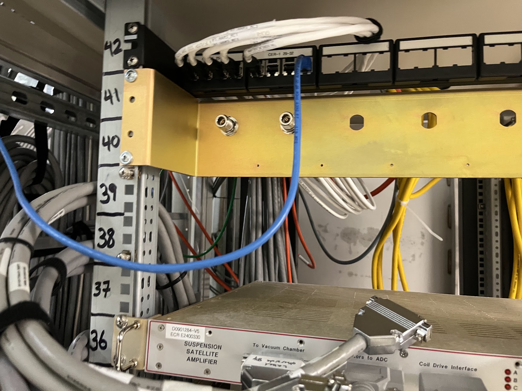
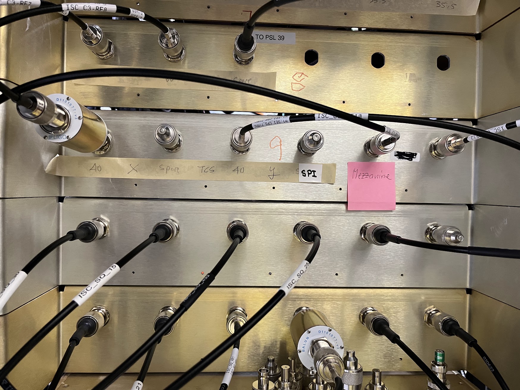
The Heliax cable for SPI was landed in ISC-C3 (Patch Panel U37/U38, port 4)
LVEA Work
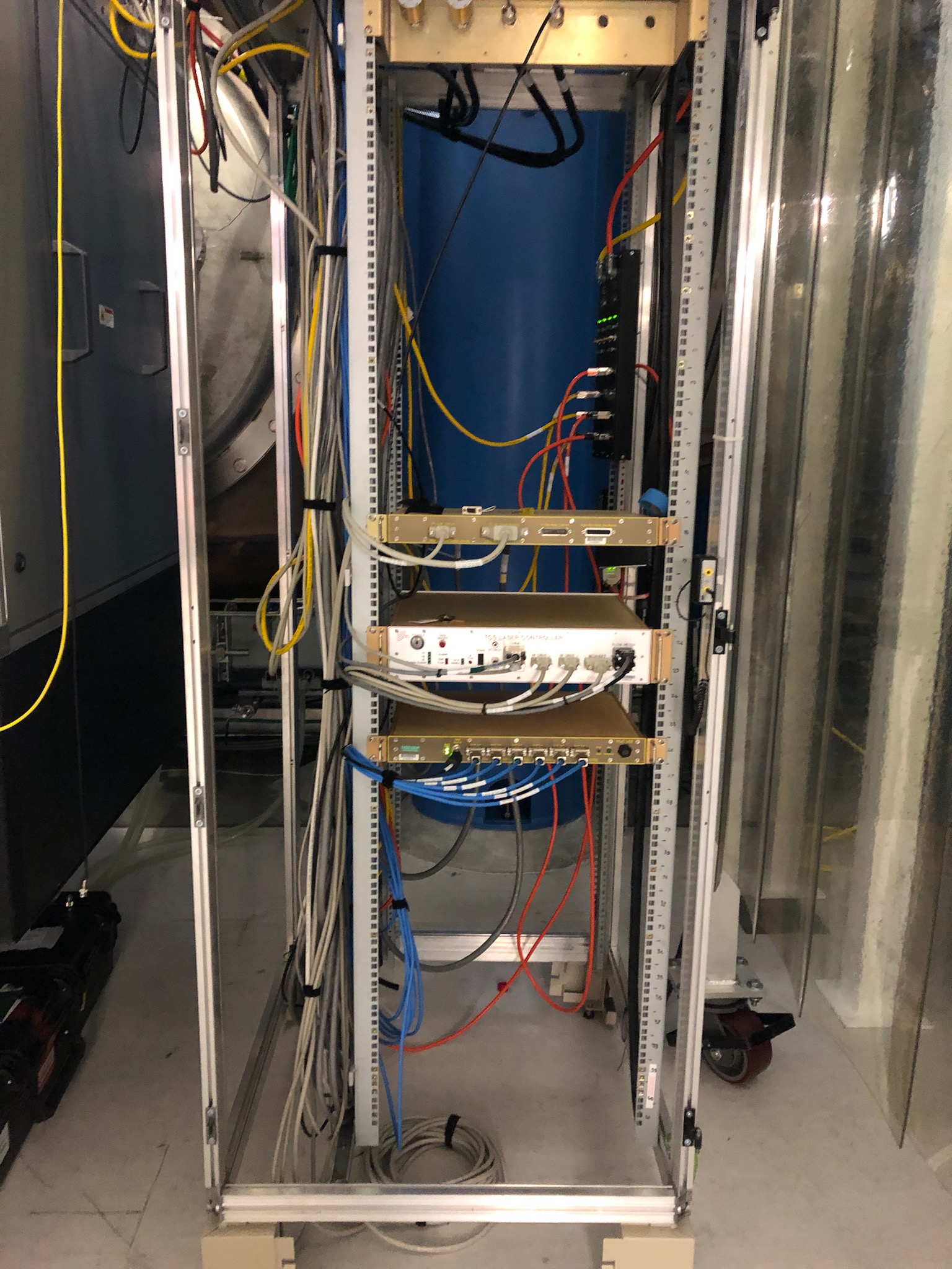
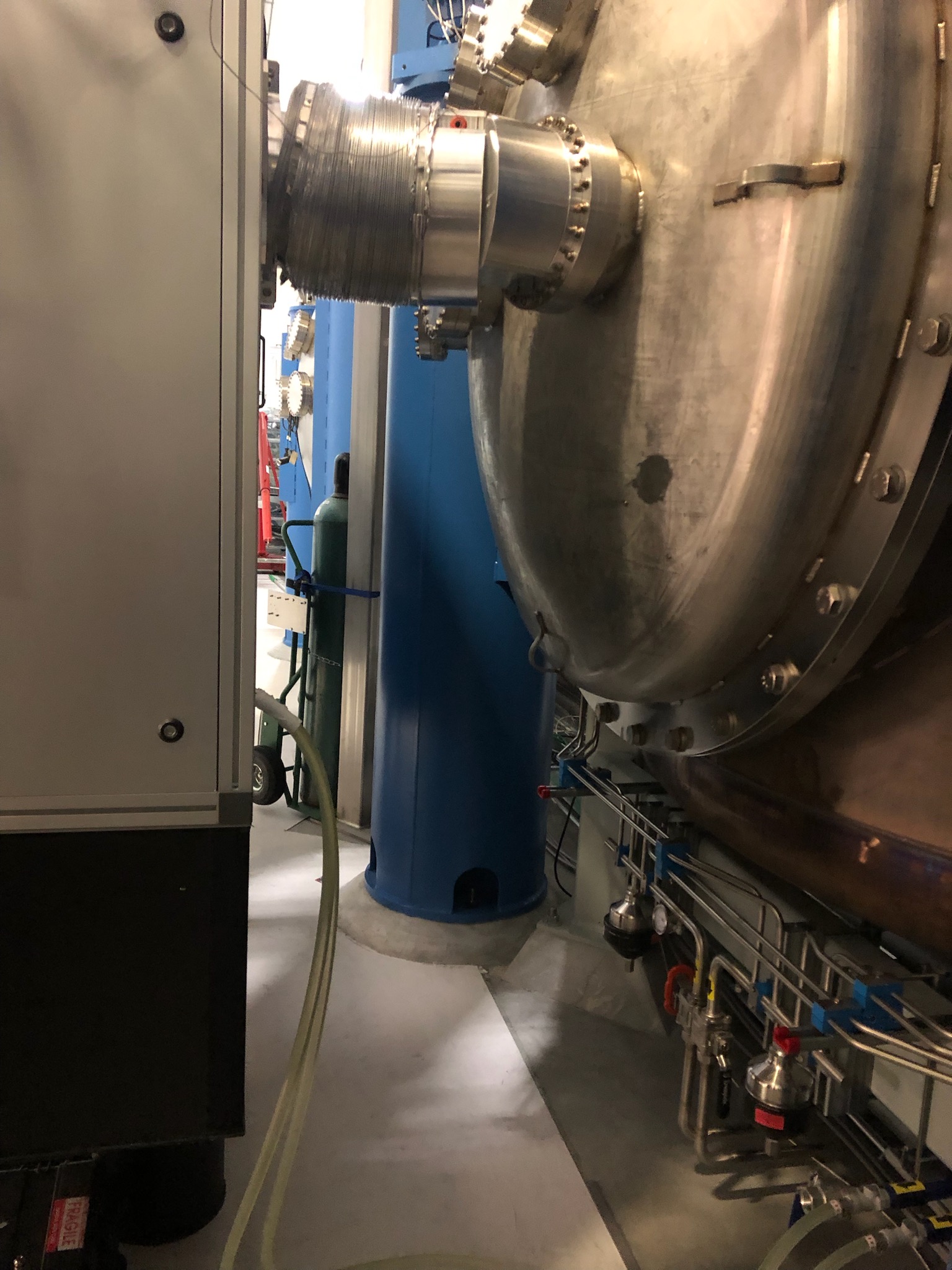
Finished routing the ±18V power cable for CHETA Y around BSC8 and BSC1. Cable was landed in the TCS-R2 rack. We spent some time cleaning cabling in the TCS rack and the space between the TCSY enclosure and BSC1.
F. Clara, C. Gray
Wed Apr 08 10:07:42 2026 INFO: Fill completed in 7min 39secs
Late entry for yesterday's fill.
TITLE: 04/09 Day Shift: 1430-2330 UTC (0730-1630 PST), all times posted in UTC
STATE of H1: Planned Engineering
OUTGOING OPERATOR: None
CURRENT ENVIRONMENT:
SEI_ENV state: MAINTENANCE
Wind: 3mph Gusts, 2mph 3min avg
Primary useism: 0.02 μm/s
Secondary useism: 0.16 μm/s
QUICK SUMMARY:
Work today is Likely going to be removing bolts from chambers HAM3, BSC1, And BSC2's Dome.
(Jordan V., Travis S., Gerardo M.)
To get ahead on door removal, we vented a couple of anuli systems, and we used nitrogen to vent BSC1, BSC2 and HAM3. No issues to report for any of the vents.
Also, we removed most of the bolts from HAM3 chamber doors.
Elenna, Madi, Oli
Today we started tackling the alignment of all the REFL optics that go on the BHSS.
A Path
The A path went relatively smoothly. We had an issue with A-R1 where we had the left side alignment template D2400130 correct and placed A-R1 in it correctly, but the angle of A-R1 was off and sent the beam into the side of the OMCA butter dish. This was possibly due to an error with the clocking tool, but since Elenna had roughly placed the downstream optics last week, we were able to easily fix it by rotating A-R1's mount until it was shooting down the right way. We then were able to get the rest of the REFL A path worked out pretty well, just not the beamdumps.
B Path
The B path caused a few more issues. First, trying to place 36-R1 using the left side template, we realized that we couldn't actually use the tooling since 36-R1 has a J-holder for the black glass, and the screw that holds the J-holder in place doesn't screw in all the way - there are a couple of threads that stick out. Those couple of threads mean that the screw is in the way of the optic sitting in place in the template. To work around this, we ended up installing B-R1 using the right side template, and once we had that we used that as a reference to get 36-R1 reflecting OMCB REFL towards it. Later, we had some trouble getting the beam to B-R3 while also keeping B-R3 at the correct screwhole. We ended up moving it over one screwhole to the left, from L8 / T13 to L9 / T13. At this point we just roughly aligned it to go towards the QPD and left it for now since we might need to move it back over. We might end up needing to shift all the optics in that line over ?
UNFORTUNATELY, we also made a mistake. We aligned B-R2 to hit the B-2 QPD, and B-R3 to hit the B-1 QPD, but it's supposed to be the other way around. We will have to correct this next time!
TITLE: 04/09 Day Shift: 1430-2330 UTC (0730-1630 PST), all times posted in UTC
STATE of H1: Planned Engineering
INCOMING OPERATOR: None
SHIFT SUMMARY:
Vacuum team has been Venting the corner station still.
OMC's were taken to SAFE for a model reboot then taken back to aligned.
Dave and Marc swapped some cables and restarted the following IOP's & models today. Please check your SDF's haven't been reverted.
H1IOPOMC0
H1IOPOAF0
H1IOPASC0
Tagging teams that may have SDF issues in the future.
SRM taken to aligned. (I have no idea Why it was misaligned.)
IMC Input Power Channel is no longer "Cray Cray" and is now reading correclty as of Jennie D's alog.
Restart ISI models BSC 1,2, & 3
FW1 Down 19:15 UTC
DC0 down 19:20 UTC
DC0 Re-established at 20:36 UTC
ISI BS Stage 1&2 watchdog tripped 20:36 Likely due to Vac activities.
ISI HAM3 WD tripped 23:33
VAC team says BSC2 annulus is vented & Dome bolts ready to be broken.
LOG:
| Start Time | System | Name | Location | Lazer_Haz | Task | Time End |
|---|---|---|---|---|---|---|
| 18:00 | FAC | Chris | H2 | N | clearing the tumbleweeds @ H2 | 21:01 |
| 19:40 | SUS | Elenna & Madi | Optics Lab | Y | aligning optics on BHSS Elenna out first | 22:39 |
| 20:01 | EE | Fil | CER | N | Rack cabling | 23:08 |
| 20:04 | SUS | Oli & Maddie | Optics lab | Y | BHSS optic alignment | 23:02 |
| 20:29 | SUS | Jeff | CER, LVEA | N | Take pictures of racks, R3 by HAM3 in LVEA | 20:46 |
| 20:53 | PSL | Jason | MER | N | Filling spare PSL chiller | 21:40 |
| 21:19 | SUS | Ibrahim, Travis | LVEA | N | Checking ergo arm | 21:28 |
| 21:23 | PSL | RyanS | MER | N | Help Jason with the chiller | 21:40 |
| 21:45 | FAC | Richard | CER | N | Talk to Fil | 22:00 |
| 22:16 | VAC | Jordan, Gerardo, Travis | LVEA | N | Vent anulus ion pump in @ 1502 | 23:58 |
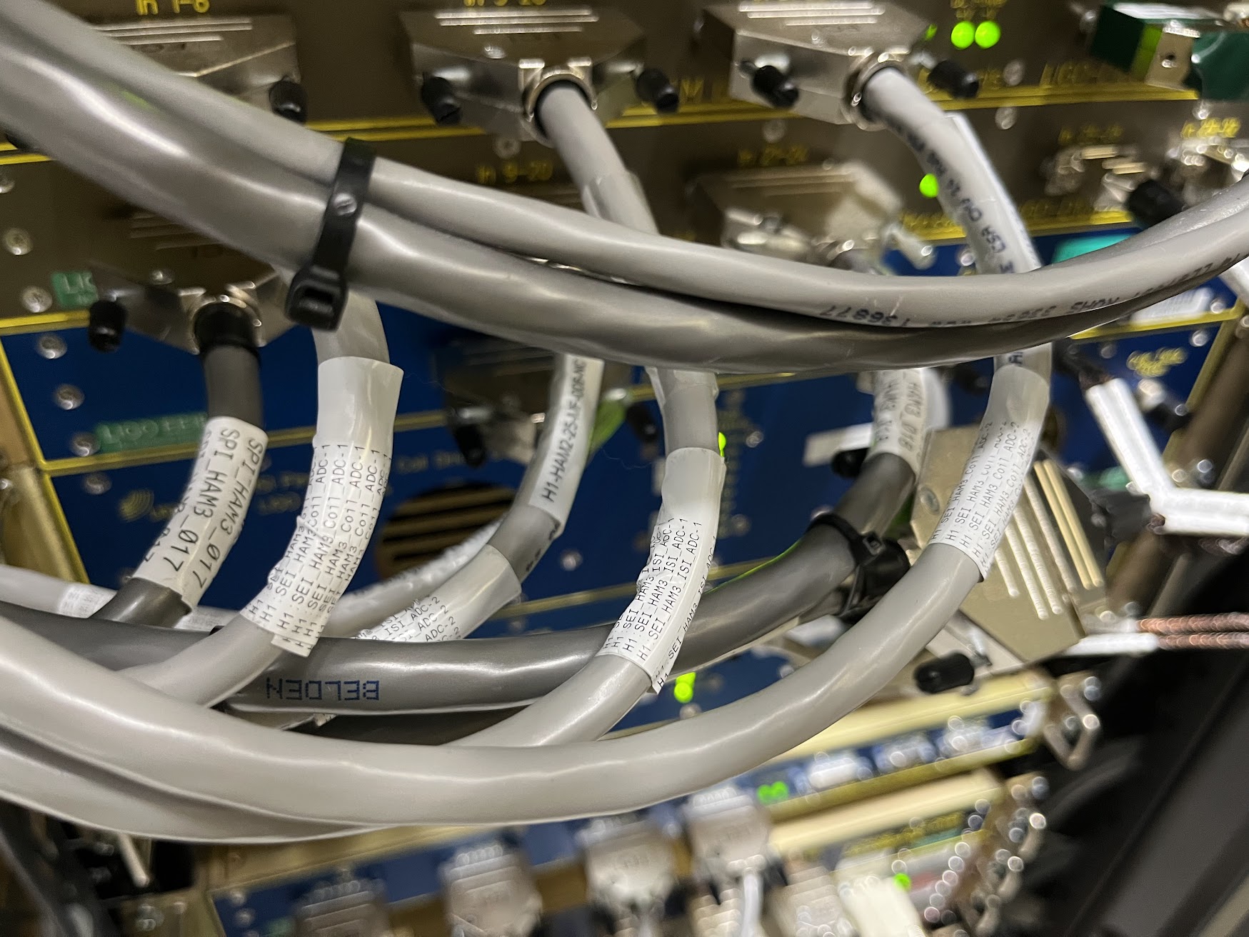
Jeff and I started looking at HAM ISI signal chains to see if there were enough AA inputs for the planned upgrades during this install cycle. We realized that we still have all of the cabling for the original distribution of STS channels, where each STS is connected to one of the BSC front-ends, the signal goes through a distribution chassis that then sends copies of that STS to each of the other front-ends before sending signal to the source front-end AA, sort a physical ipc. This means each HAM rack has 3 db9 AA ports taken up by a signal distribution chain we no longer use, each BSC has 2.
Until today, ITMY sent its collection of 1 directly connected STS set of channels (the HAM2 (or A) STS) and 2 distributed sets (ITMY (or B) from BSC2 and HAM5 (or C) from BSC3) over IPC to SEIPROC, where it was calibrated, then used for a sensor correction signal that got sent back out to all of the corner seismic. This means we can free up AA ports by removing the rat-king STS distribution set up and just use the IPCs. Doing this required redistributing the IPCs for each STS to the front end model the ground sensor was directly connected to.
Arnaud is working on the ECR (with the helpful cartoon of what is being changed in p. 2 here), but I wanted to test the changes needed to do this today. I disconnected the extra connections for the shared STS signals between each BSC, leaving just the AA cable for each chambers directly connected STS. I then split out the 9 IPCs from ITMY to each chamber. Dave and EJ found a bug where I had mistakenly used an ADC selector instead or a bus, so I also fixed that in a couple places on the top level for each chamber. Somehow this had been before this point, but today meant the wrong channels got picked out for the BS STS IPCs. Dave also had to do some editing of some other files that had to do with the IPCs, because the sender models were changing, but not the names of the IPCs.
As far as I can tell at the moment this seems to be working. Corner is vented, so testing sensor correction performance will be difficult, but I can at least check that the signals look like ground motion and do a couple other checks.
WP13110 IO Chassis Timing Card Firmware and Sync Ribbon Upgrade
Marc, Erik, Dave:
The timing card sync ribbon cable and the timing card firmware were upgraded on the following front ends
| front end | firmware | ribbon | models built RCG5.5.2 |
| h1omc0 | already done | yes | all [h1iopomc0, h1omc, h1omcpi] |
| h1lsc0 | yes | yes | already done |
| h1oaf0 | yes | yes | already done |
| h1asc0 | yes | yes | already done |
Corner Station BSC ISI GND STS shuffle
Jim, Erik, EJ, Dave:
The 9 GND STS channels (X,Y,Z for A,B,C) were being read by h1isiitmy and sent to seiproc via 9 PCIE IPC channels.
Today's change was to reduce those handled by h1isiitmy to the "A" set of three. Add the "B" set to h1isibs and the "C" set to h1isiitmx.
IPC senders have TX slow channels in the INI file, so a DAQ restart was required to remove the "BC" channels from itmy and add them to bs and itmx.
We chose to not change the name of the IPC channels, they remain H1:ISI-ITMY_[A,B,C]_GND_[X,Y,Z]_IPC_PCIE. Technically they are incorrect for those on BS and ITMX since they retain their ITMY designator.
Keeping the ITMY names meant we did not have to remove channels from the H1.ipc file. That being said, this file did need a hand edit to change the sending model/frontend for the channels which moved to bs, itmx. This was needed so these models could build without RCG reporting "channel already exists on another model".
After h1isi[itmy, bs, itmx] were restarted with the new code, the DAQ was restarted (no EDC restart).
Jim then found that the signals for the new IPC channels were not correct, for example h1isibs was sending the wrong ADC signals, the ADC channel numbers were offset by 3.
We tracked this down to a problem with the bus-creator -> goto-tag -> ADC-bus_selector chain between the ADC selector and the IPC parts. Jim cleaned this up by replacing all of this with 3 goto-tags for the X, Y and Z channels.
After a second round of model restarts I verified the correct ADC channels were being read and sent to h1seiproc.
Wed08Apr2026
LOC TIME HOSTNAME MODEL/REBOOT
10:08:13 h1omc0 ***REBOOT*** <<< Timing Card Upgrades
10:09:39 h1omc0 h1iopomc0
10:09:52 h1omc0 h1omc
10:10:05 h1omc0 h1omcpi
10:27:06 h1lsc0 ***REBOOT***
10:28:44 h1lsc0 h1ioplsc0
10:28:57 h1lsc0 h1lsc
10:29:10 h1lsc0 h1lscaux
10:29:23 h1lsc0 h1sqz
10:29:36 h1lsc0 h1ascsqzfc
10:38:53 h1oaf0 ***REBOOT***
10:40:36 h1oaf0 h1iopoaf0
10:40:49 h1oaf0 h1pemcs
10:41:02 h1oaf0 h1tcscs
10:41:15 h1oaf0 h1susprocpi
10:41:28 h1oaf0 h1seiproc
10:41:41 h1oaf0 h1oaf
10:41:54 h1oaf0 h1calcs
10:42:07 h1oaf0 h1susproc
10:42:20 h1oaf0 h1calinj
10:42:33 h1oaf0 h1bos
11:51:23 h1asc0 ***REBOOT***
11:52:59 h1asc0 h1iopasc0
11:53:12 h1asc0 h1asc
11:53:25 h1asc0 h1ascimc
11:53:38 h1asc0 h1ascsqzifo
12:12:12 h1seib1 h1isiitmy <<< First round of new ISI models
12:12:42 h1seib2 h1isibs
12:13:10 h1seib3 h1isiitmx
12:15:44 h1daqdc1 [DAQ] <<< DAQ restarts for ISI models
12:15:54 h1daqfw1 [DAQ]
12:15:55 h1daqtw1 [DAQ]
12:15:59 h1daqnds1 [DAQ]
12:16:04 h1daqgds1 [DAQ]
12:17:31 h1daqgds1 [DAQ] <<< GDS1 second restart needed
12:21:08 h1daqgds0 [DAQ]
12:21:16 h1daqfw0 [DAQ]
12:21:16 h1daqnds0 [DAQ]
12:21:16 h1daqtw0 [DAQ]
13:22:13 h1seib1 h1isiitmy <<< Second round of new ISI models with new IPC channels corrected
13:22:37 h1seib2 h1isibs
13:23:02 h1seib3 h1isiitmx
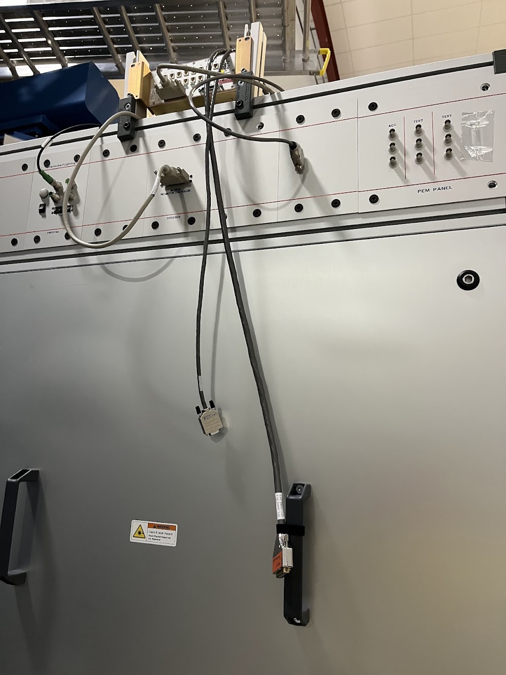
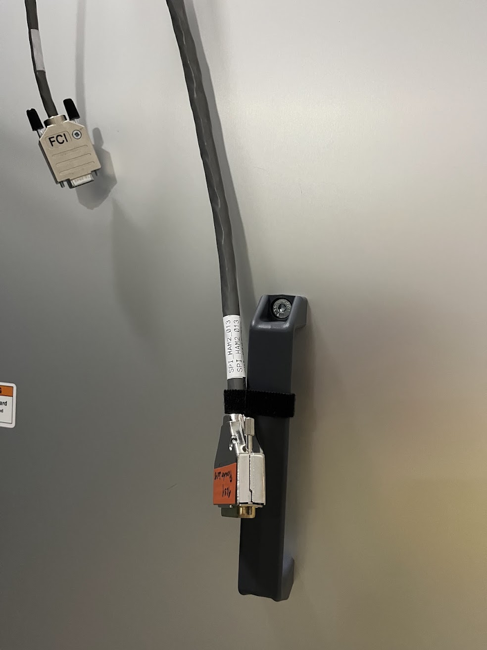
F. Clara, M. Pirello, J. Kissel D2400111 G2401479 Fil and Marc have been doing the bulk of the work installing the diversity of cabling for SPI, as governed by D2400111 (and aided by slides in G2401479). What they started in LHO:89641 they've continued to the point of "we're as ready as we can be before we get the last of the electronics from the optics lab." Here're some pictures of the status as of this afternoon. I'll attach them as comments to group them into a more digestible format. A further step we can and will take in the coming days is to set up and power-budget the RF signal chain up to the point of the double mixer chassis, since this is not needed for the remaining optics-lab testing of the ISIK transceiver (which now must be redesigned; see E2600106).
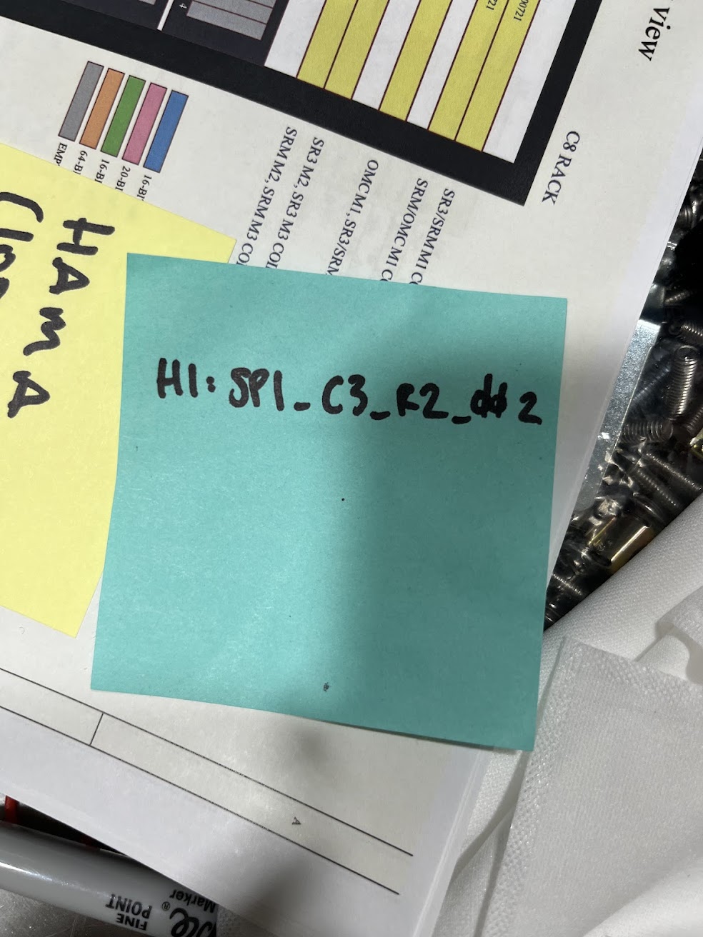
Pictures of the RF delivery of 80 (or 10) MHz from ISC-C3 remote CER rack to SUS-R2 field rack by HAM3. 2026-04-08_SPIElectronics_ISC-C3_RF_PatchPanel_01.jpg Front of patch panel in ISC-C3 U36-U37, which where SPI 80 (or 10) MHz is sent out to the floor on port 4 (marked in the picture as "SPI"). 2026-04-08_SPIElectronics_ISC-C3_to_SUS-R2_HeliaxCable_Name.jpg The heliax cable in between the patch panels has a temporary name "SPI_CABLE_1." In the current version of the wiring diagram (D2400111-v6), this is called "SPI_RFDist_002," but that was merely an uninformed place-holder name. This will be augmented both in reality and in the wiring diagram to be what's on the sticky-note to better match existing cable naming convention, "H1:SPI_C3_R2_002." 2026-04-08_SPIElectronics_SUS-R2_RFPatchPanel_Back.jpg Heliax as it arrives at back the SUS-R2 U41-U40 patch panel. 2026-04-08_SPIElectronics_SUS-R2_RFPatchPanel_Front.jpg Port 1 (furthest left as you look at the rack) will be live with 80 (or 10) MHz.
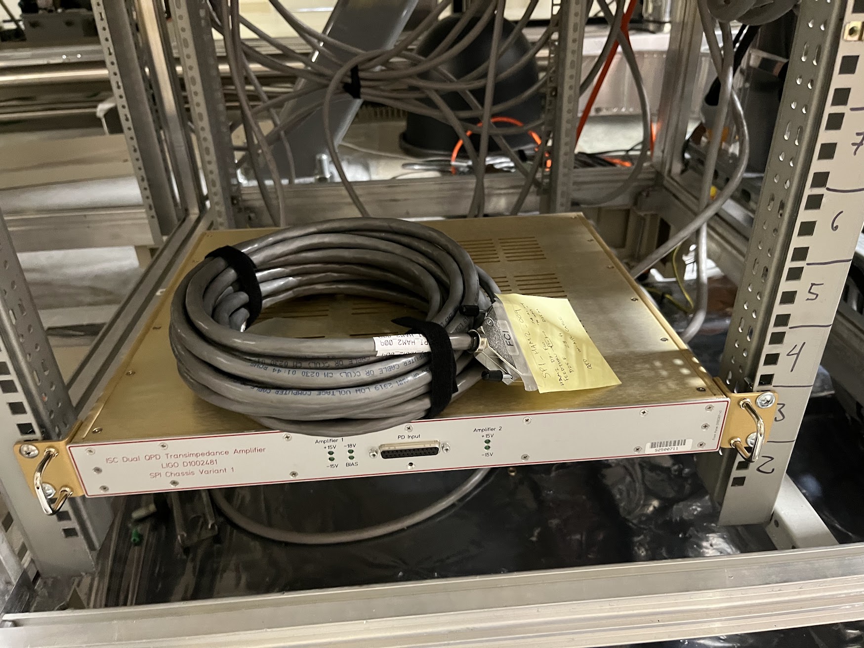
ISIJ Field Cables 2026-04-08_SPIElectronics_SUS-R1_ForISIJ_Cables_01.jpg Shows both cables - SPI_HAM2_009 ISIJ's QPDA "from HAM2 feedthrough to Variant 1 TIA" D25 cable lying on top of that S2500711 chassis installed last week into SUS-R1 U3 (LHO:89752). - SPI_HAM2_010 ISIJ's QPDA "from Variant 1 TIA to CER SEI-C2 U27" long cable run, velco strapped to the adjacent waterfall cable tray. 2026-04-08_SPIElectronics_SUS-R1_ForISIJ_Cables_02.jpg Just a different view of the same TIA in SUS-R1 U3.
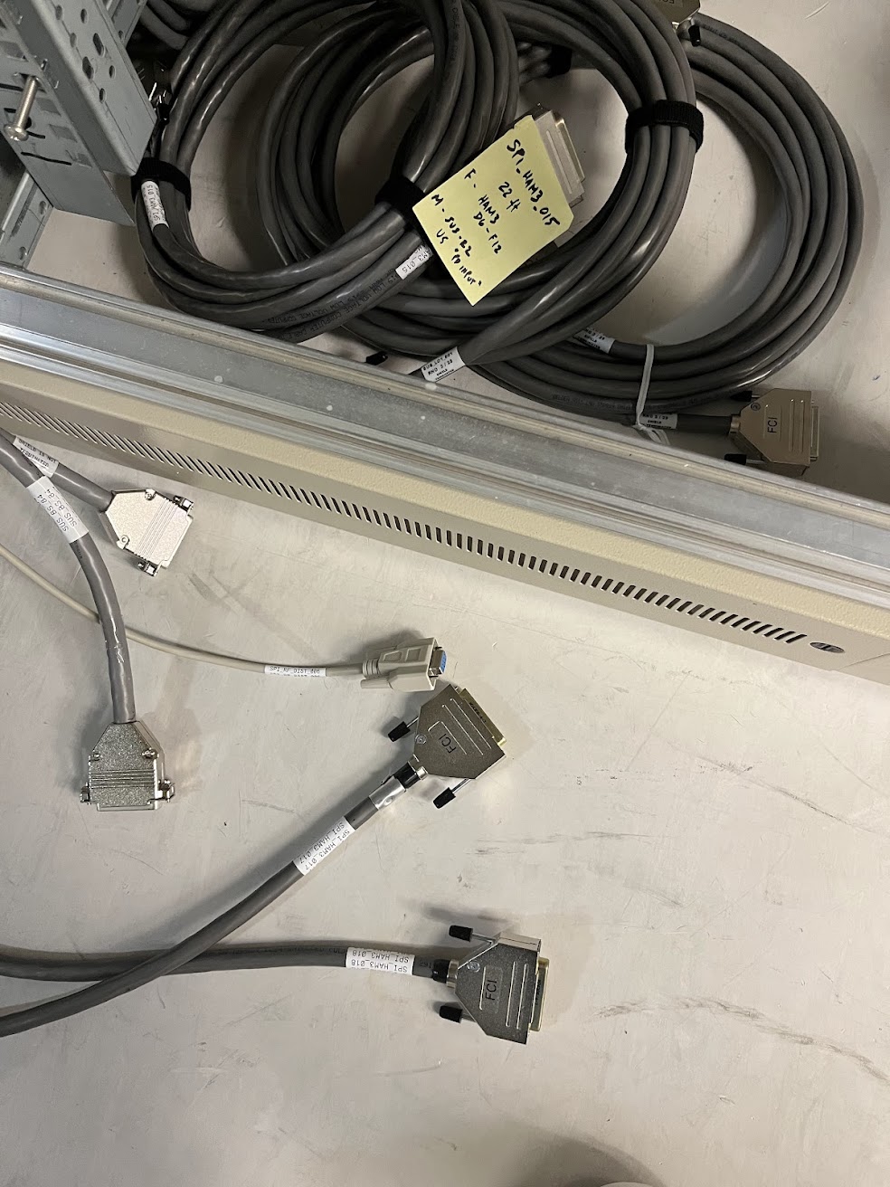
ISIK Field Cables 2026-04-08_SPIElectronics_SUS-R2_ISIK_Cables.jpg All audio-frequency SPI cables that go to-and-from SUS-R2. - SPI_RFDist_006 delivering 4096 Hz via D9 cable to SUS-R2. - SPI_HAM3_015 that will take all ISIK PD signals from HAM3 chamber feedthru to TIAs in SUS-R2 - SPI_HAM3_017 and SPI_HAM2_018 that will ISIK's PDs from Variant 2 S2500712 and Variant 3 S2500713 TIAs to SEI-C2 AA/ADC channels.
ISIK Picomotor Control Cables Pictures of TCSY Table, upon which an 8CH picomotor controller lives, that has a spare D25 output (CHs 5-8). This will get connected to SPI_HAM3_013 which goes from there to the HAM3 chamber.
SEI-C2 ADC/DAC Cabling Here we show the consumption of all spare channels and ports on the h1seih23 computer's ADC3 AA, including some y-cable gymnastics to work around the personality of the SEI-C2 U27 D1000269 AA chassis. We also see how there's another y-cable coming from the last CH13-16 port of the SEI-C2 U26 D1100202 AI chassis, to scrounge out the last two unused channels of the ISI HAM3 DAC1, with one leg of the cable needed to keep sending CH13 and 14 to the corner 3 H and V coil drivers of the ISI, and the other leg connecting to the long D9 SPI_RFDist_006 cable that sends 4096 Hz to SUS-R2.
FAMIS 28641
pH of PSL chiller water was measured to be between 10.0 and 10.5 according to the color of the test strip.
Per WP13110 we have upgraded the IO chassis listed below.
This link contains the asbuilt for all of the H1 IO Chassis: https://dcc.ligo.org/LIGO-D1301004
This link contains the ECR for the IO Chassis sync cable upgrade: https://dcc.ligo.org/LIGO-E2600069
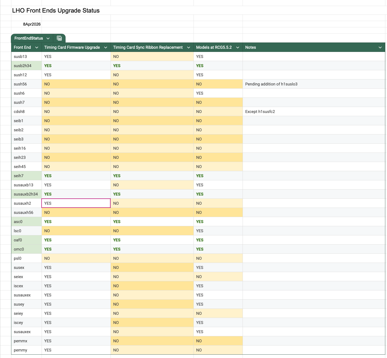
This link is to the work in progress spreadsheet LHO Front Ends Upgrade Status
Corner:
SUSB2H34 has upgraded firmware and sync
SUSAUXB2H34 has upgraded firmware and sync
SEIH7 has upgraded firmware and sync
OMC0 has upgraded firmware and sync
OAF0 has upgraded firmware and sync
ASC0 has upgraded firmware and sync
LSC0 has upgraded firmware and sync
Here is the current IO Chassis upgrade status:
Completed the following upgrades today. While making rounds I took time to check the Kepco power supplies and found one failed but not tripped, EX-VDD2-U22-RHS Rotor Locked, +/-18V ISC_C1 S1203039. Will exchange at earliest convience.
EX:
H1SUSAUX_EX already had latest firmware, sync cable upgraded
H1SUS_EX already had latest firmware, sync cable upgraded *
H1ISC_EX already had latest firmware, sync cable upgraded
H1SEI_EX already had latest firmware, sync cable upgraded
* H1SUS_EX has 2 LD32 DAC's without heatsinks. It also has a 3rd fan installed.
MX:
H1MX already had latest firmware, sync cable upgraded
EY:
H1SUSAUX_EY already had latest firmware, sync cable upgraded
H1SUS_EY already had latest firmware, sync cable upgraded
H1ISC_EY already had latest firmware, sync cable upgraded
H1SEI_EY already had latest firmware, sync cable upgraded
MY:
H1MX already had latest firmware, sync cable upgraded
Started the day upgrading IO chassis:
Corner:
PSL0 has upgraded firmware and sync
SUSAUXH2 has upgraded firmware and sync
SUSAUXB13 has upgraded firmware and sync
SEIH16 has upgraded firmware and sync
SUSAUXH56 has upgraded firmware and sync
FCAV:
CDSH8 has upgraded firmware and sync
Mechanical Room Mezzanine:
SUSH6 has upgraded firmware and sync
SUSH7 has upgraded firmware and sync
CER:
SEIB1 has upgraded firmware and sync
SEIB2 has upgraded firmware and sync
SEIB3 has upgraded firmware and sync
SEIH23 has upgraded firmware and sync
SEIH45 has upgraded firmware and sync
SUSH56 has upgraded firmware and sync
SUSB13 already had latest firmware, sync cable upgraded
SUSH12 already had latest firmware, sync cable upgraded
All IO Chassis Upgraded, closing WP13110.
erik v, dave b, filiberto c, marc p.
We started the venting process for the corner today, including the FCB1 section of the filter cavity attached to BSC3
GVs Closed:
GV2, GV5 (GV7 remains soft closed until repairs are done on the piston cylinder), RV1, FC1, 2, 4, 5.
Dry air dewpoint at vent port = -40.3C
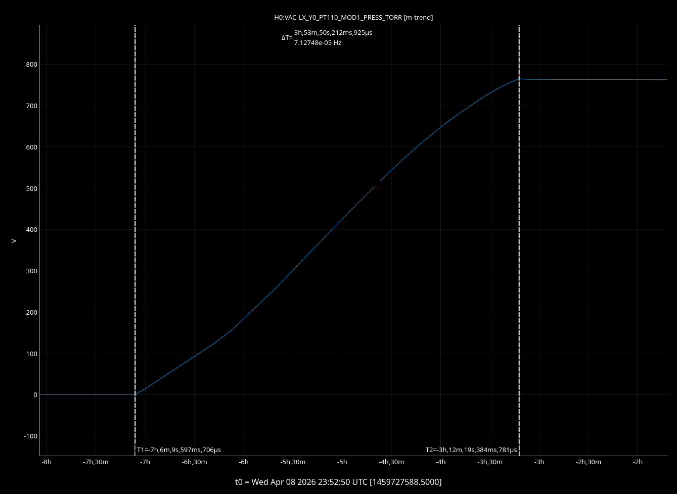
We followed the venting procedure E2300169, until the small burp of dry air into the corner volume, during this "burp" we noticed a small pressure increase at PT114 (CP1 gauge on beamtube side of GV5). There was a clear pressure step from 2.02E-9 to 2.04E-9 Torr at the same time as the dry air burp, see attachment.
We waited for ~15 minutes and repeated the air burp into the corner, again we saw another pressure increase at PT114, though the pressure gauge on the opposite side of CP1 PT124 showed a small decrease at the same time as the pressure increases.
We paused the vent to investigate, PT120, PT114 and PT124 are all pirani/CC gauge pairs and we are investigating if there is any potential crosstalk at the vacuum rack that could be causing this.
More to come.
Corner Vent resumed today, we burped purge air one more time to ~1 torr no pressure step seen on the opposite side of the gate valves.
Continued procedure E2300169, dew point at the purge air point of entry was -44.0C
No further issues encountered, total vent time was ~4 hours, with PT110 up to ~770 torr (PT120 pirani needs atmosphere calibration currently reading ~900 torr).
XBM is currently isolated via GV2 and soft closed GV7, pressure is being maintaned by the XBM turbo station.
Closing WP13153