TITLE: 03/25 Day Shift: 1430-2330 UTC (0730-1630 PST), all times posted in UTC
STATE of H1: Planned Engineering
INCOMING OPERATOR: None
SHIFT SUMMARY: GV7 is still broken and will not hard close, HAM1 vent prep work, the PSL incursion was completed, and the BHSS work continues in the Optics lab.
LOG:
| Start Time | System | Name | Location | Lazer_Haz | Task | Time End |
|---|---|---|---|---|---|---|
| 14:15 | FAC | Kim, Nellie | LVEA | N | Tech clean | 14:54 |
| 15:05 | VAC | Gerardo, Jordan | LVEA HAM1 | N | Open ION pump | 15:09 |
| 15:08 | FAC | Randy | LVEA WBay | N | Craning Test stand, *not over the tube* | 16:12 |
| 15:19 | SEI | Jeff | Optics lab | LOCAL | Turn off laser | 15:27 |
| 15:28 | SEI | Camilla, Jeff | Optics lab | N | Parts search / checks Camilla out 15:45 | 15:48 |
| 15:35 | SEI | Jeff, Camilla | LVEA | N | Grab power meter | 15:45 |
| 16:02 | TCS | Sophie | Prep lab | N | CHETA work | 16:19 |
| 16:08 | EE | Marc, Fil | LVEA H1,2 | N | Cabling fiber, SUS to SAFE | 18:58 |
| 16:19 | Betsy | CER/Clean storage, Optics lab | N | Put away garb and other stuff | 16:37 | |
| 16:20 | BHD | Elenna, Keita | Optics lab | N | BHD/BHSS work | 17:26 |
| 16:22 | SQZ | Camilla | LVEA, SQZT7 | LOCAL/HEIGHT | SQZT7 table alignment, bringing glasses for Fil, Marc | 16:33 |
| 16:33 | PSL/SPI | Jeff, Jason, Sina | PSL, Racks, PSL encl | N / LOCAL | SPI fiber work, Jason out 18:30 | 18:46 |
| 16:39 | FAC | Kim | LVEA | N | Tech clean | 18:09 |
| 16:46 | FAC | Randy | LVEA WBay | N | Test stand work | 17:39 |
| 16:48 | ISC | Ibrahim | CER/ Clean storage | N | Inventory C3 covers | 19:21 |
| 16:48 | SQZ | Camilla, Sheila | LVEA | LOCAL | SQZT7 work, LOCAL and HEIGHT LASER HAZARD | 17:04 |
| 16:59 | ISC | Jenne | LVEA | N | Talk to Camilla/Sheila | 17:02 |
| 17:06 | BHD | Oli | Optics lab | N | BHD/BHSS work | 17:40 |
| 17:17 | ISC | Jennie | Optics lab ->LVEA | N | Check for parts, put away in LVEA | 17:35 |
| 18:23 | SPI | Bram | LVEA | N | Check with Jeff out with Jeff | 19:11 |
| 18:35 | VAC | Travis | Site | N | VAC property inventory | 21:53 |
| 18:37 | VAC | Gerardo | LVEA | N | Turn on purge air for HAM1 | 19:13 |
| 18:39 | OPS | Betsy, Tony | LVEA | N | Double checking LASER SAFE status | 19:11 |
| 19:17 | OPS | Tony | LVEA | N | Grab paper and table keys | 19:22 |
| 19:29 | FAC | Randy, Jim | LVEA | N | Turn on HAM1 CR and work on the test stand Jim out 20:20 | 20:27 |
| 19:34 | ICS | Camilla, Calum | Optics lab | N | Check on parts | 19:52 |
| 20:09 | SEI | Jeff, Bram, Sina | Optics lab | LOCAL | SPI work | Ongoing |
| 20:18 | TCS | Sophie | Prep lab | N | CHETA work | 21:03 |
| 20:21 | SUS | Oli | LVEA | N | Take picture of a rack | 20:25 |
| 20:32 | BHD | Elenna | Optics lab | LOCAL | BHSS work | Ongoing |
| 20:34 | PEM | RyanC | CER | N | Swap dm comms cables | 20:41 |
| 20:37 | SUS | Oli | Optics Lab | LOCAL | Working BHSS system | Ongoing |
| 20:40 | SQZ | Sheila | SQZT7 | N | Checking for people working at height to transition. | 21:02 |
| 20:41 | EE | Fill | CER | n | Grounding cables | Ongoing |
| 20:51 | VAC | Gerardo | LVEA | N | Take off turbopump | 21:02 |
| 21:01 | EE | Betsy, Marc, Tony | Vac Prep | N | Cable testing | Ongoing |
| 21:49 | OPS | Ibrahim | CER / Clean storage | N | C3 cloth covers checks | 22:18 |
| 22:35 | Calum | Vac Prep lab | N | Talk to Betsy | 23:20 | |
| 22:58 | VAC | Jordan | LVEA | N | Grab parts by HAM1 | 23:03 |
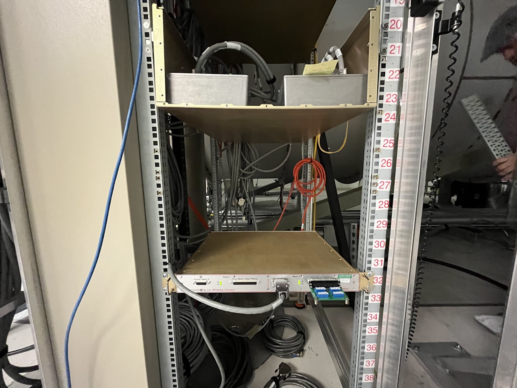
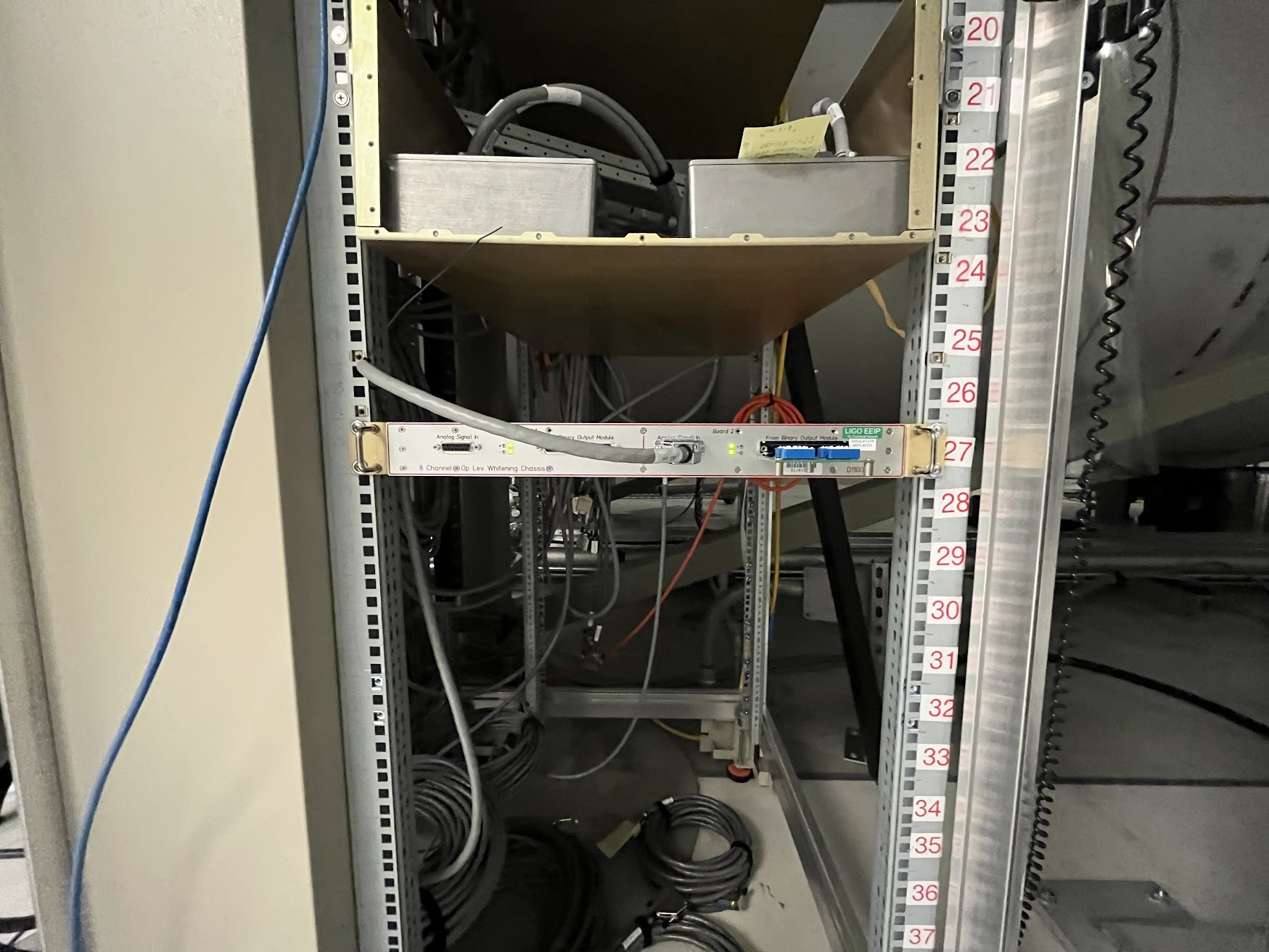
J. Kissel, M. Pirello While in SUS-R2 and thinking SPI, and looking at the proposed rack layout from G2401479, and accounting for all the SUS (BBSS, LO1, LO2) that's incoming for O5 -- I found that SPI can have a bit more space if we just move the SUS-PR3 optical lever whitening chassis up 5 U-heights from "32" to "27." I put the u-height in quotes because this is an old style rack with the u-heights labeled from top down, rather than the bottom up per industry convention. I would have and could have gone higher, but the 27 slot already had mounting clips in it, so I went there. We can go as high as "25" if need be in the future. Pics of before vs. after are attached.
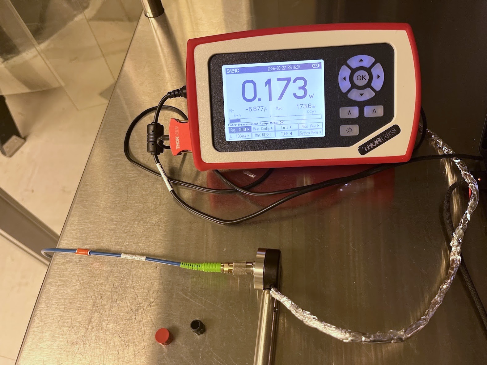
F. Clara, J. Kissel, S. Koehlenbeck, J. Oberling, M. Pirello D2400110 Today we picked up where we left off with the install of SPI into H1. Where we last left things, we'd installed a new SPI pick-off of ALS/SQZ beam in Apr 2025 (see ECR E2400083 and results in LHO aLOGs 83989, 83996, 83978). Back then, we had ended the work with the input to the fiber collimator within the PSL dumped. With Jason and Sina in the PSL, we confirmed that the SPI path was still blocked. However, we also realized/remembered/confirmed that the entire ALS/SQZ/SPI path had 25% less power -- We've been running the PSL at lower power allocation downstream of the PMC since Sep 2025 to prevent issues we'd found with the currently installed EOM after a power outage triggered a dust monitor to spew out dust into the PSL (see that saga in e.g. LHO:87109 LHO:86966). They found the power at the SPI pick-off was 140 [mW] instead of the 188 [mW] we left in Apr 2025 (see LHO:83996). (Using labels in the half-up-to-date drawing D1300348) Jason and Sina rotated ALS-HWP2 upstream of ALSPBS01 to restore the nominal 50 [mW] into the ALS/SQZ pick-off and ~200 [mW] (190 [mW] measured). This means there's ~50 [mW] less out to ALS / ISCT1 than before today. Then with the SPI pickoff still dumped, we installed a 30 [m] patch cord*** from the PSL optical table, out the mouse hole between the +X wall of the PSL enclosure and HAM1, then up running along the upper racks to waterfall down at SUS-H2. The fiber sits within the typical orange tubing. Per D2400110, this is SPI_PSL_001, and it's labeled as such on both ends. After install, I connected the SUS-R2 end to a Thorlabs S121C power meter with S120-APC2 fiber adapter. With this installed (making the system laser safe at SUS-R2 end), Jason/Sina unblocked the SPI pickoff input. With 190 [mW] in, we measure 187 [mW] out on the other end. 98% transmission, pretty excellent. Almost unbelievably excellent but we weren't rigorous with our uncertainty and systematics. Happy with this result, we then blocked the SPI path again, and re-capped the SUS-R2 end for final dressing in the racks. We'll unblock again when we're read to connect it to the Laser Prep Chassis. ***Patch cord details: Manufacturer DIAMOND DIAMOND Part Number: ENS/1094388 Customer Part Number: 9711228 Patchcord SM L=30 PM 2xFC 2mm APC (i.e. 2mm narrow key FC/APC on both ends) tran 6,6/125/245 PAND 980nm
J. Oberling, S. Koehlenbeck 2026-03-27 #BelatedaLOG During this power measurement, I made the rookie mistake of overlooking the PM100D power meter console's laser wavelength setting -- and not taking a picture of the display during the measurement. Today, we both (a) retook the measurement at 1064 [nm] with 189.3 [mW] input, and found 173 [mW] output. (b) confirmed that at 532 [nm] the output read as 188 [mW]. For now we set the nominal power into the laser prep chassis as 173 [mW]. After this measurement, we took this same power meter (S121C) and fiber adapter (S120-APC2) into the optics lab and instead used the fiber-coupled NPRO we'd been using to test ISIK in there. We measured the power out of the fiber (i) with it fiber-coupled in the same way as the SPI_PSL_001 measurement, and (ii) using an addition PAF2-5C collimator to project the beam into free space on to the power meter. We set the FC-NPRO's power to 177 [mW] in the (i) configuration, but then measured 140 [mW] in the (ii) configuration. This leads us to suspect that the S120-APC2 + S121C system -- a reflective Si diode, with a shiny metal adapter -- is errantly reporting more power than there really is. We'll repeat the measurement of SPI_PSL_001 another day with a thermal power meter to arrive at our final number.
During the last two days CDS EE has completed the following:
This completes dirty work over HAM1 and HAM2. In the next two weeks, will close out work in SUS-R2 before HAM3 is vented.
List of items needed for SUS-R2:
F. Clara, J. Kissel, J. Oberling, M. Pirello, T. Sanchez, and R. Thompson
S. Muusse, C. Compton
0920 QCL unit failure summary:
We were beam profiling the laser and I had the profiler ~8” from the laser head, with a steering mirror to steer onto the scanner. Laser was at 1A. I blocked and unblocked the beam but as it was unblocked there was a beep and there laser controller turned off with message “LD output voltage protection was tripped”.
I then turned controller off and back on again with power down to 0.5A and it would not turn on.
Camilla then came into the lab, we turned off and unplugged controller. It was turned on again, would not turn on. Remembering LLO's issues, on the Temperature Protection screen we eased the +-5 deg requirement to +-6. Laser then appeared to turn on with “laser current reading 0.500 A” and “laser voltage reading 10.440V”, temperature 25deg. However no beam was coming from the laser.
We then turned off and on laser. Again appeared on but no beam, slowly turned up current from 0.5A towards 1A, at 0.84A controller beeped with “LD output voltage protection was tripped” message again.
QCL Unit q-parameter dependance on laser temperature:
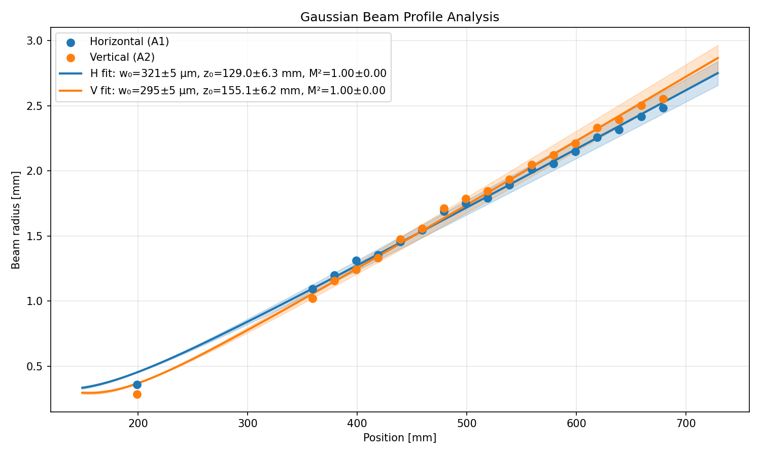
Unit failure happened while profiling the laser to check if the q-parameter of the QCL has a temperature dependence. This profiling was done largely at a 23mm offset with one point near the waist. However, there was not an opportunity to take more measurements around the waist in this new data because of the failure which may cause some inaccuracies in the fitted q. I used a non linear fit where M2=1. This is consistent with the fitting by Matt. His measurements were completed at 20 deg but after advisement from thorlabs we have increased operating temperature to 25 deg.
| Temperate [deg] /date | Horizontal [mm] | Vertical [mm] |
| 20 / 2025-09 | - 174 + 67i | - 209 + 56i |
| 25 / 2026-03-24 |
-129 ± 6 + 71 ± 2i |
-155 ± 6 + 59 ± 2i |
With the new q factors there is slightly better agreement between the fitted q-parameter for L2 and the model.
Vertical
| Measurement/model | w0 [ µm] | z [mm] | w at ITM [mm] |
|
Fit from data: |
978.9±22.7 |
-1063.1±33.8 |
50.09 |
| Fintrace q: - 209 + 56i (old) |
857.11 |
-500.64 | 61.38 |
| Fintrace q: -155 + 59i |
992.56 |
671.38 |
54.083 |
Horizontal
| Measurement/model | w0 [ µm] | z [mm] | w at ITM [mm] |
| Fit from data | 1280.3+/-54.9 |
-1813.3±83.5 |
38.01 |
| Fintrace q:- 174 + 67i (old) |
979.42 |
-653.71 | 54.38 |
| Fintrace q: -129 + 71i |
1127.3 |
-866 |
47.939 |
Wed Mar 25 10:11:55 2026 INFO: Fill completed in 11min 52secs
Sheila, Camilla
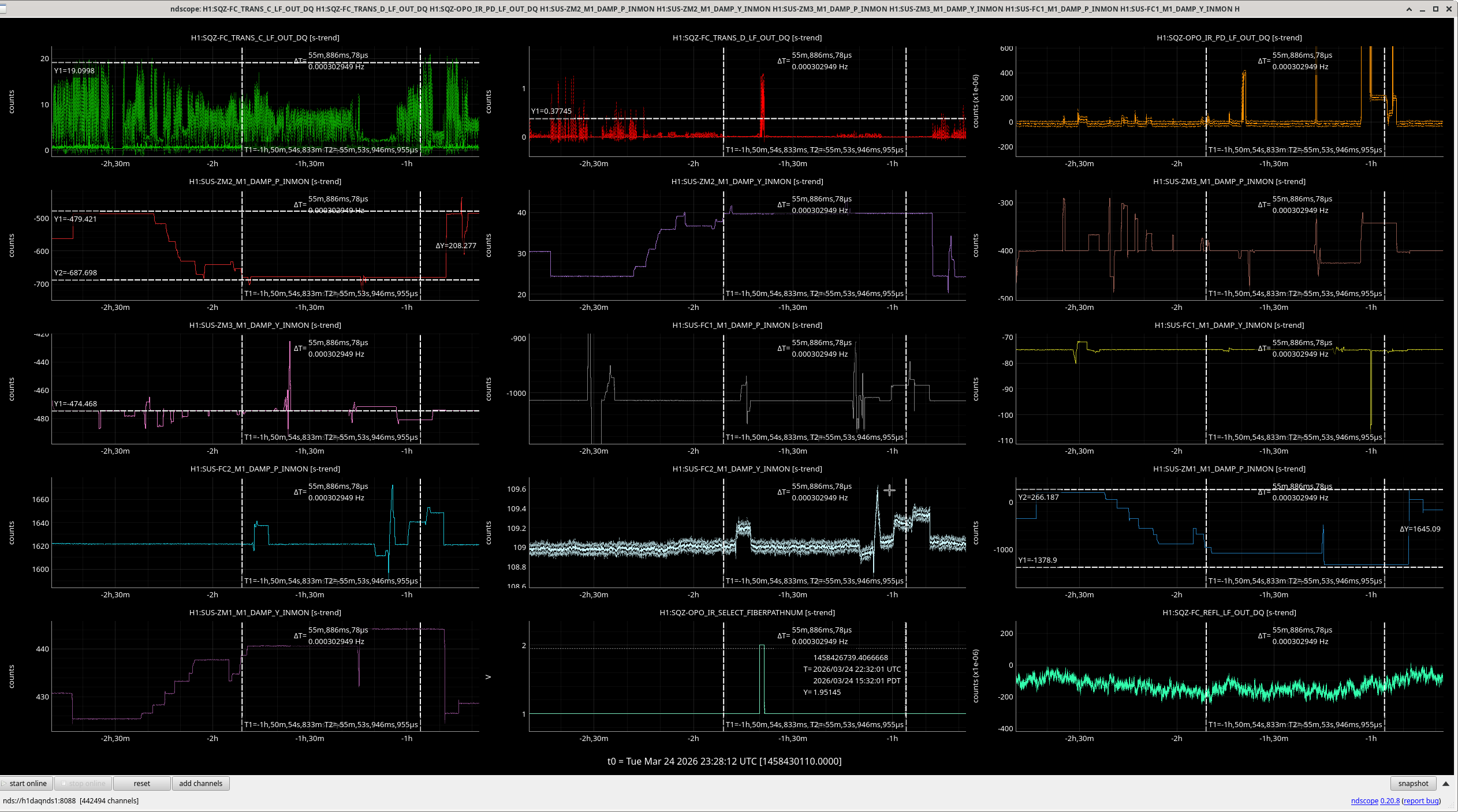
While we had good green (20) and IR (1) FC flashes, we had to move 100urad in ZM3 positive PIT to get any light on SQZT7 OPO IR PD, see -2h30 on screenshot.
We then walked ZM1 and ZM2 both in negative PIT (which seems a bit weird but worked) until we only had to move ZM3 13urad to get light on SQZT7. However in doing this move, we lost the majority of IR light and some green light, see t-cursor #1 of screenshot. I injected the SEED beam at this point and the IR FC camera looked again like a strange cross or swallow bird. I hoped to move ZM3, FC1 and FC2 to bring back IR light but wasn't able to.
I was able to get good green flashes simultaneously with SQAT7 IR light but then I had no IR FC light, see t-cursor #3 of screenshot, 22:35UTC.
Vicky reminded us of 2022 when we had to pico to get FC green/IR co-resonance: 66017, 66281
Sheila, Jenne, Camilla
Today Sheila and I went onto SQZT7 to try to align the FC green REFL beam onto the diode so we could lock the FC in green. Could see on the periscope that the FCGS REFL beam was clipped. Sheila remembers it was not clipped last week before she pico'ed the green beam so we Jenne and I went back to where we had good IR and green FC flashes and undid Friday's 89596 pico-ing. This made the green yaw beam look much worse and flashes decrease as expected.
I then went back to here we had green FC flashes with IR on SQZT7 and repeated when we did yesterday but with YAW, moving ZM1 and bringing flashes back with ZM2 in the direction to de crease the amount ZM3 needed to move to get light back on SQZT7. I did completely loose the FC IR beam doing this though in going to the green FC flashes with IR on SQZT7 place.
TITLE: 03/25 Day Shift: 1430-2330 UTC (0730-1630 PST), all times posted in UTC
STATE of H1: Planned Engineering
OUTGOING OPERATOR: None
CURRENT ENVIRONMENT:
SEI_ENV state: CALM
Wind: 5mph Gusts, 2mph 3min avg
Primary useism: 0.02 μm/s
Secondary useism: 0.23 μm/s
QUICK SUMMARY:
The JAC seems to be failing to lock. I'm not sure why, but since it's just scanning I assume it's fine for the night. But, if someone with more JAC experience thinks it's useful to log in and set it to DOWN for the night, that would be good.
After talking to Keita, I set the JAC to Down.
Betsy reminded me that the IOT table was unplugged in prep for venting, and that's why JAC was failing to lock.
TITLE: 03/24 Day Shift: 1430-2330 UTC (0730-1630 PST), all times posted in UTC
STATE of H1: Planned Engineering
INCOMING OPERATOR: None
SHIFT SUMMARY:
Hard closing GV7 continues (no luck today). New platform craned into place between BSC2+3. Filter Cavity gate valves opened for more Squeezer alignment. Lots of cable/fibers pulled in the LVEA. Optics Lab was busy with Team SPI & Team BHSS work (as well as Team CHETA lab next door).
LOG:
J. Oberling, R. Crouch
In talking with Calum about the upcoming pre-deintall BS measurements, I realized that in the middle of JAC install I completely forgot to write an alog about the WBSC2 support tube FARO survey Ryan and I did at the beginning of February. So, here it is.
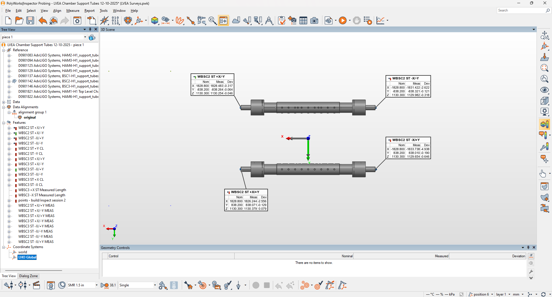
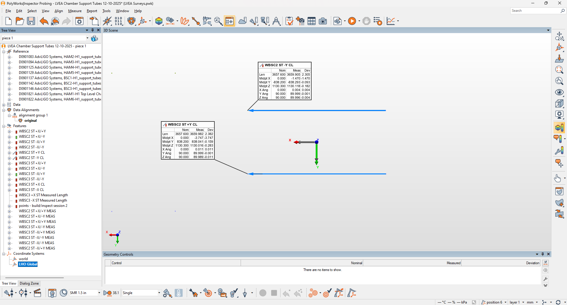
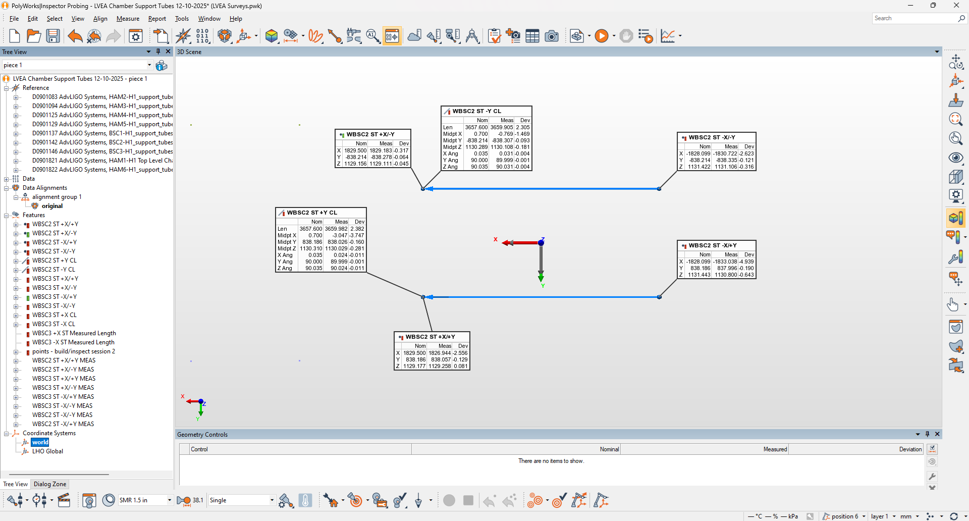
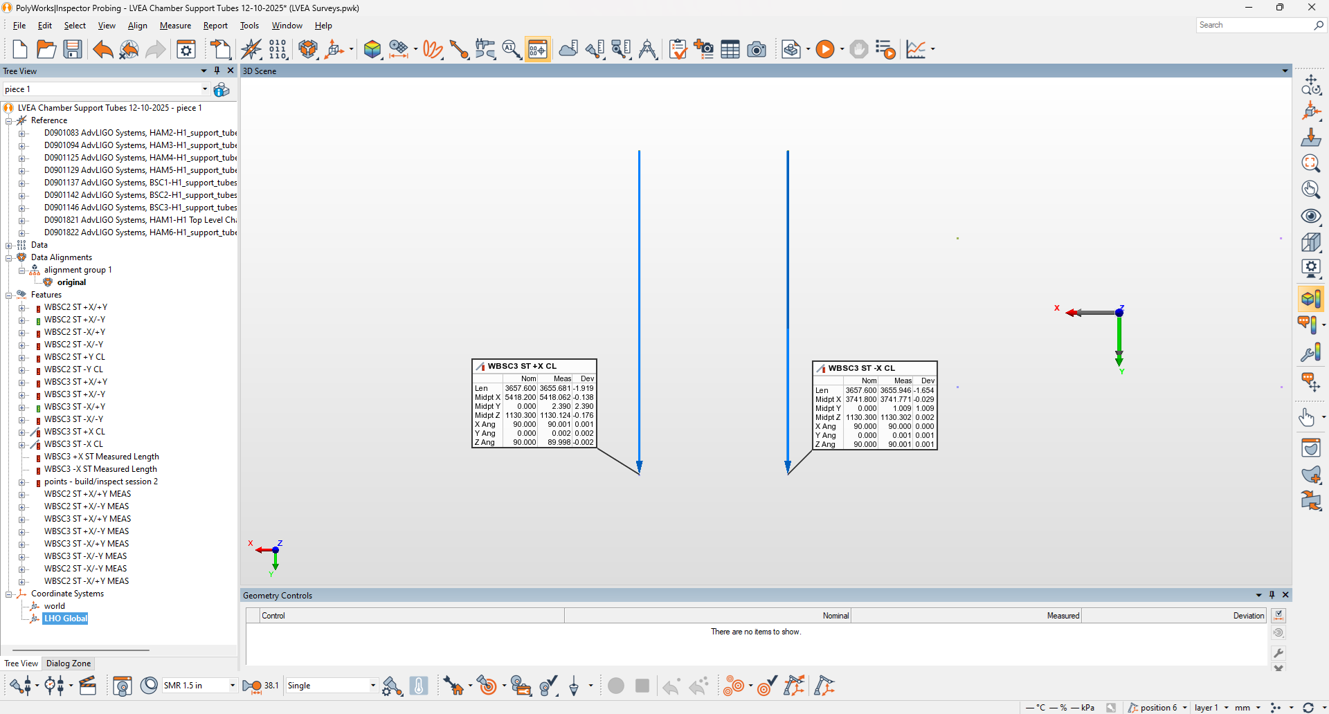
Following the same procedure we used to survey the support tubes for WBSC3 and the +X ends of WBSC2 (alog 88620), we surveyed the -X WBSC2 support tube ends. The results are shown in the 3 attachments; the first 2 are in the LHO Global Coordinate system and are the images I will be discussing. The 3rd attachment contains all info from the first 2, but in the Corner Station building Local Coordinate system (included for completeness; for more on LIGO coordinate systems, see T0900340). The first attachment shows the surveyed locations of the support tube ends, while the 2nd shows information regarding the midpoint location of the support tubes and their angles w.r.t. the IFO axes (the line shown represents the centerline of the support tube created from one end point to the other; the Nominal column (Nom) comes directly from the CAD model, while the Measured column (Meas) is our measured data. Some interesting things to note here:
Now keep in mind that the support tube locations may not be indicative of a misalignment of the BS optic itself. When we installed this we only cared about putting the BS where it needed to be, and HEPI (and by extension the support tube ends) was wherever it (they) needed to be to support that. We will be taking measurements of the BS SUS cage and the optic itself once the corner is vented (likely to be one of the 1st activities after the vent), and we'll know more about the location of the BS optic once we have done so.
(Travis S., Jordan V., Richard M., Gerardo M.)
Last Friday we tried to "hard close" GV7, but we only achieved a "soft close" status. After looking at the system that uses instrument air at the gate valve, we did noticed that the solenoid valve to "open" and "close" the gate valve was "leaking" air, lots of instrument air, to fix the air leak we decided to replace the solenoid valve with a new one.
Then when it was time to "hard close" GV7, its pressure regulator broke, we were not able to open the regulator. We ordered a couple of new regulators and should be here on Wednesday. Meanwhile we are going to "hard close" the gate valve using a bottle of nitrogen.
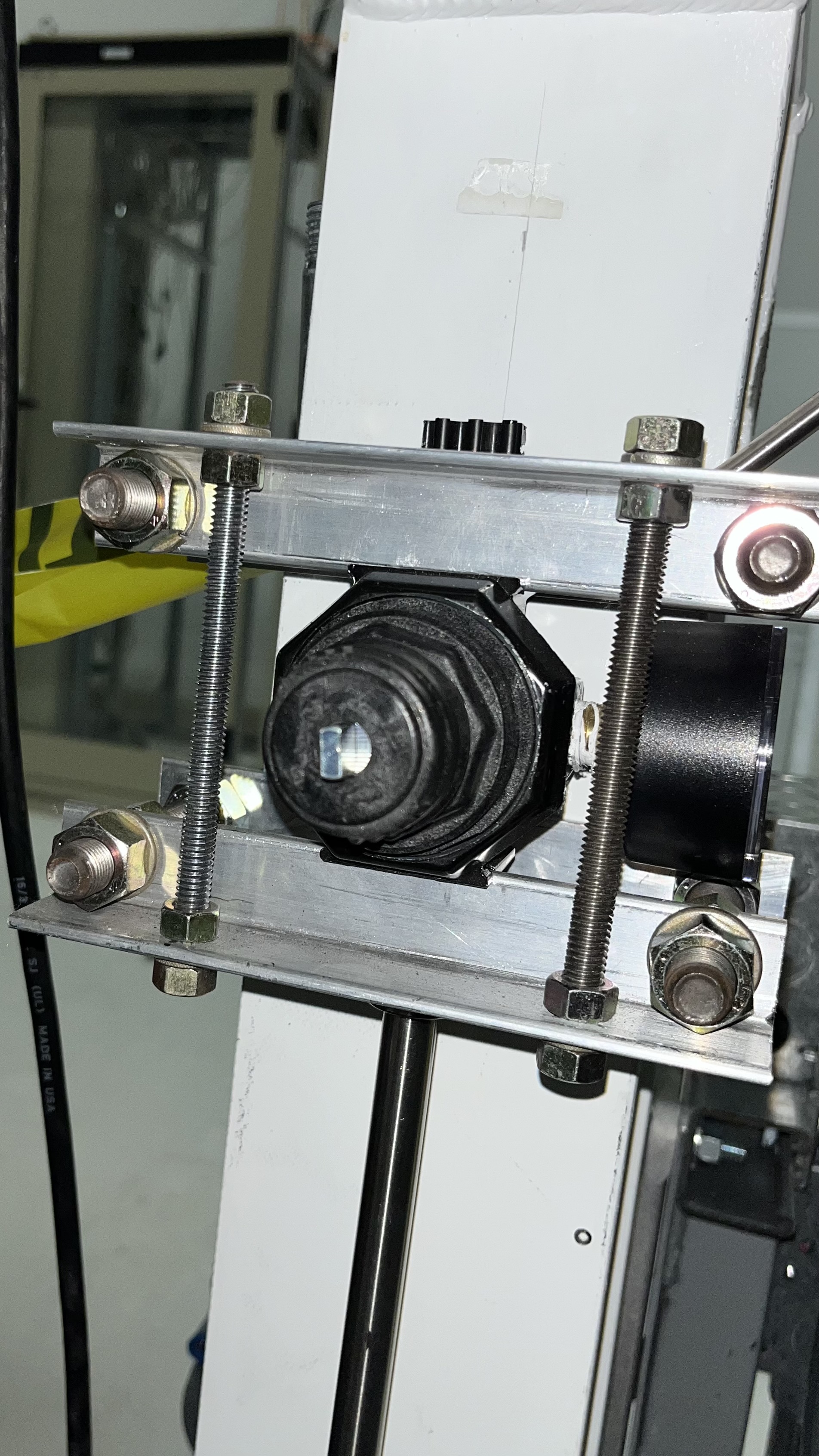
Attached is a photo of the broken regulator, yes the knob is off, but the metal piece within is free floating and not able to do its job.
(Travis S., Jordan V., Richard M., Gerardo M.)
We bypassed the gate valve instrument air regulator and feed bottled air to the gate valve actuation system directly. We continued where we left off, and just continued to apply pressure to the system in an attempt to "hard close" the gate valve, and a second approach was to open the gate valve and close it again.
Leaky sound noted, we did noticed that when we are on the "close" setting, there is lots of hissing sound coming from one of the "relief ports" at the solenoid valve, but when we are on the "open" setting, there is no hissing at the solenoid valve. And if there is is very small.
We previously reported that the wiring to ground on the OMCA DCPD dsub9 cables seemed odd, see 89562. There appears to be two conflicting diagrams of the pin wiring, D2200276 and D2300119. Neither of these diagrams follow the correct pin naming practice either.
Today, Oli and I checked the ground connectivity for the OMCB DCPD dsub9. The case ground is wired to what is labeled pins 6 and 9, according to both of the diagrams above and also proper convention. However, this is different from OMCA, where the case ground is wired to pins 2 and 5 (following the incorrect naming of the diagrams above), or pins 1 and 4 (following correct naming conventions).
So either way, we have two different wiring set ups for OMCA and OMCB. We have only checked the ground pins so far, and it seems like we should confirm the cathode and anode wiring as well.
To summarize:
- we have two different diagrams for pin wiring
- OMCA and OMCB are wired differently from each other
- the diagrams are not following proper pin naming convention which is making this more confusing
Two problems with the drawings.
1. Case grounding.
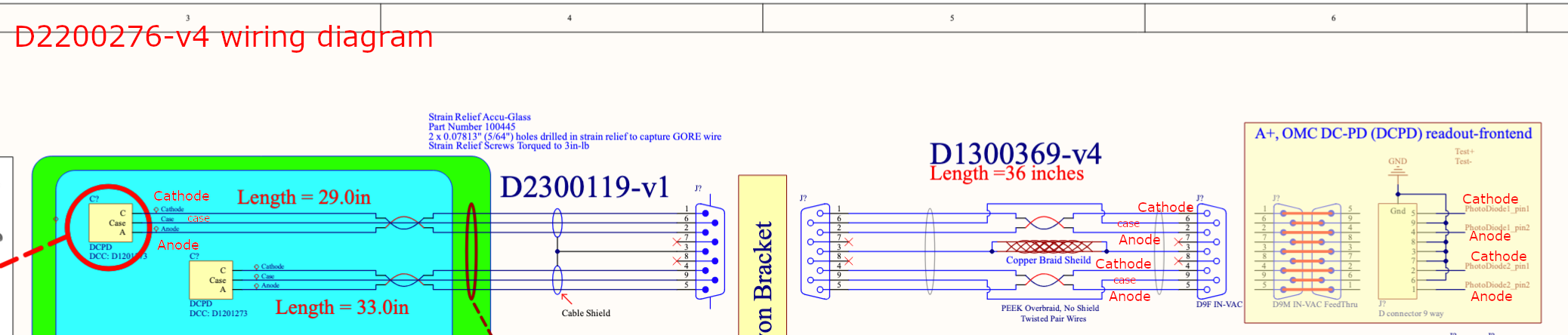
As for cable and connection drawings, D2200276-v4 wiring diagram specifies that pin1-2 and pin4-5 twisted pairs carry the photocurrent, pin1 and pin4 being cathode, and case grounds are routed to pin6 and pin9, between DCPDs and the in-vac DCPD frontend. See the 1st attachment.
D2300118 DCPD to DB9M cable doesn't agree with the wiring diagram, it routs the case grounds to pin 2 and pin 5. See the 2nd attachment.
D1300369 DB9F-DB9F cable drawing agrees with the wiring diagram in that pin1-2 and pin4-5 are twisted pairs.
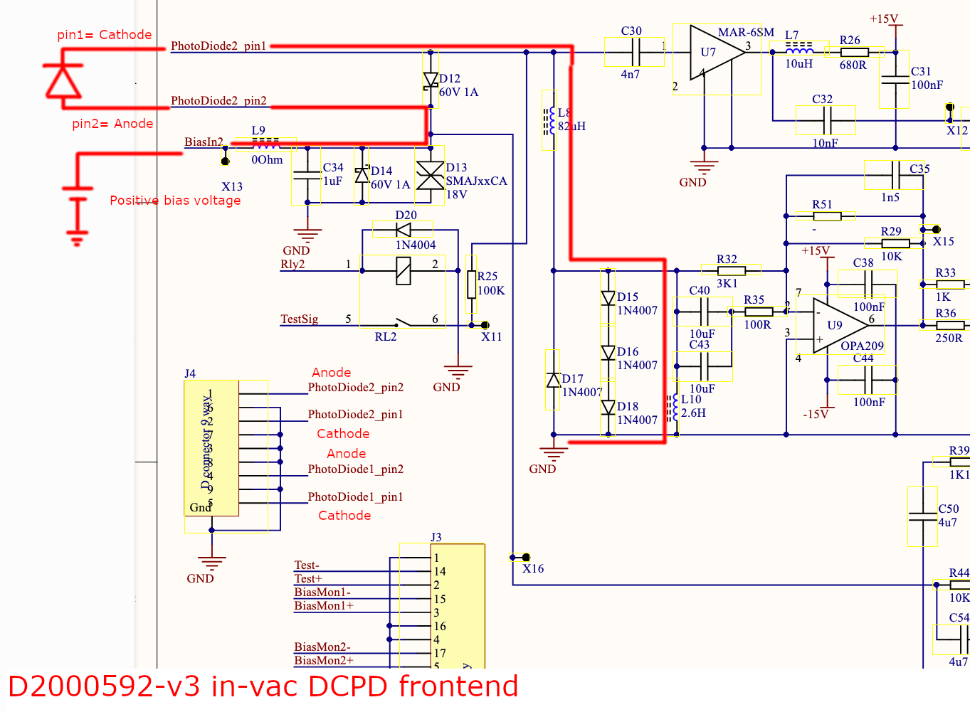
D2000592-v3 in-vac DCPD frontend seems to be compatible with the wiring diagram in that it routs the pin6 and 9 to the ground.
So, D2300118 DCPD to DB9M cable drawing is singularly incompatible with others.
Below is a summary table of the above together with reality check of the DCPD-DB9m cable. It seems that there's no way OMCA cable works. Anode/Cathode check wasn't performed (yet).
| pin1 | pin2 | pin6 | pin4 | pin5 | pin9 | |
| D2200276-v4 wiring diagram | Cathode1 | Anode1 | Case1 | Cathode2 | Anode2 | Case2 |
| D2300118 DCPD to DB9M cable | Cathode1 | Case1 | Anode1 | Cathode2 | Case2 | Anode2 |
| D1300369 DB9F-DB9F cable (pass through) | compatible with the wiring diagram in that pin1-2 and pin4-5 are twisted pairs. | |||||
| D2000592-v3 in-vac DCPD frontend (outside of the enclosure feedthrough) |
Internally routed to PD1 pin1 |
Internally routed to PD1 pin2 |
Internally routed to GND |
Internally routed to PD2 pin1 |
Internally routed to PD2 pin2 |
Internally routed to GND |
| OMCA reality | Case | ? | ? | Case | ? | ? |
| OMCB reality | ? | ? | Case | ? | ? | Case |
2. Polarity of the diode seems to be wrong.
Assuming that the wiring diagram and the in-vac DCPD frontend circuit diagram are both correct, cathode1 and anode1 are routed to "PD1 pin1" and "PD1 pin2" while cathode2 and anode2 are routed to "PD2 pin1" and "PD2 pin2". So, pin1 and pin2 inside the frontend chassis are cathode and anode. Again look at the first attachment.
However, whey you look at the circuit diagram of the frontend (3rd attachment), pin2 is connected to the positive bias and pin1 is grounded (via the huge inductor). This means that the PD is forward-biased and will be unusable. Is this only in the drawings?
What to do.
First thing is to check the diode polarity in reality, i.e. if cathode is routed to pin 1 and 4 (which I expect) or to pin 2 and 5 (which I don't expect). In parallel, check with Ali/Dean that my assessment of the polarity makes sense or not.
Depending on the results of the polarity investigation, we'll determine which cable needs to be reterminated how. If we're lucky we'll just reterminate only one cable, but if the PD polarity is indeed wrong we'll have to reterminate all cables.
Here is a further update. This is based on conversations with Keita and Betsy, and emails to and from CIT and LLO.
At first, it appears one issue here is that I have made a mistake OMC placement, as D2200276 indicates that OMCB should have the DCPD cable labeled D2300119 (and PZT cable D2300121), and OMCA should have D2300118 (and PZT cable D2300120), and I installed them opposite according to the DCPD cables. This doesn't account for the wiring issue; it would only make a cable length difference.
Oli and I went into the lab to swap around OMCA and OMCB, and realized that one OMC has the DCPD cable for A (D2300118) and PZT cable for B (D2300121) and vice versa. So it's not clear which is which.
Keita has further pointed out that this wiring issue with the grounding pins could indicate cathode and anode are swapped, which means that the diode will be forward biased, which is a much bigger issue.
Therefore, we're pausing on all BHSS work for now until we can figure out how to resolve these problems.
LLO has not checked their wiring, but Oli and I did note that they paid attention to the OMC labeling since they knew the cable lengths would be different.
When our OMCs were shipped to us, the ameristat wrapping had OMC A and OMC B labels, but once we took the wrapping off, there was no indication of A and B on the boxes.
Keita, Elenna, and I just went in and tested the direction the current is flowing for the DCPD cables (D2300118 and D2300119).
D2300118 (SN S2500546)
Current direction:
- Pin 2 -> 1
- Pin 5 -> 4
D2300119 (SN S2500548)
Current direction:
- Pin 6 -> 1
- Pin 9 -> 4
We verified that there was no current flow when probes were swapped
For posterity, Ali etc. confirmed that the bias voltage is carried by pin 1 and 4 between the DCPD and the in-vac frontend: https://alog.ligo-la.caltech.edu/aLOG/index.php?callRep=80660
This means that the latest (fixed) version drawing for DCPD-D9M (https://dcc.ligo.org/D2300118-v2 and https://dcc.ligo.org/D2300119-v2) are correct, which is a good news!
This also means that the wiring diagram https://dcc.ligo.org/D2000592 is incorrect and the circuit diagram for the in-vac frontend https://dcc.ligo.org/D2200276 is incorrect or lacking information about the connection between the D9M feedthrough and the D9M connector on the board (e.g. the connection cable inside the box is not a usual cable but gender-changer type).
R. Crouch, J. Oberling
Yesterday we began measuring the locations of the vacuum chamber support tube ends using the FARO laser tracker. We started with the support tubes for the WBSC3 chamber and the +X ends of the WBSC2 support tubes as these were the most readily accesible. The remaining support tubes in the LVEA (WBSC1, WBSC2 -X ends, and all WHAM chambers except WHAM7) have iLIGO-era PEM Interface Plates on them that block the support tube; some of these plates have undocumented spacers between them and the support tubes they are attached to, meaning we cannot accurately locate the support tube end w.r.t. the PEM interface plate and therefore making an accurate measurement of the support tube location impossible. As an aside, Jim is in the process of removing these plates from the chambers (so far WHAM3 and WHAM4 are complete, WHAM1 and WHAM2 are 75% complete), so we can get at these support tube ends as the opportunity arises (he will then reinstall these plates, as they make for very convient mounts for dial indicators).
Measurement Method
This is a fairly straightforward measurement, but there is a somewhat subtle "gotcha" that needs to be accounted for to get an accurate measurement. But first things first, we aligned the FARO to the LVEA's Building Coordinate system using our red alignment nests, then applied the X and Y axis rotations required to align the FARO to the site global coordinate system (see T0900340 for a brief overview of the coordinate systems in use). We then loaded CAD models of the support tubes, that Ryan downloaded from the SolidWorks vault with each model in the site global coordinate system, into the FARO's control software, PolyWorks. PolyWorks automatically reads the coordinate system information contained in the CAD files and places these models in position w.r.t. to the site global coordinate system. This gives us nominal locations of the support tube ends, a guide for our measurements, and also a nice visual reference for where everything is positioned.
Now for the "gotcha." The physical support tubes have a hole in the center of each end that is not represented in the CAD model, and this hole is large enough that the FARO target (a Spherically Mounted Retroreflector, or SMR, with a 1.5" diameter) sits slightly inside the hole. This means that when you're taking a measurement of the center of the support tube end using this hole the SMR is not measuring the location of the actual support tube end, it is a few mm inside of it. To account for this we did the following:
To take the measurement we used the Build/Inspect mode in PolyWorks. In this mode we have to be sure to select the "Towards Object" compensation method, which automatically compensates for the radius of the SMR (3/4", or 19.05 mm). If "None" is selected the FARO measures to the center of the SMR, but our measurement point is at the edge of the SMR, since that's what is physically touching the support tube, so we need to compensate for that radius. This gives us the deviations of the measurement point, which can then applied to the point representing the center of each support tube end to give their measured location. The results of our measurements are shown in the attachment. Since we had measurements for each end of the WBSC3 support tubes I also added a distance feature representing the measured length of each WBSC3 support tube.
Wrapping Up
Some points for discussion/further thought. Keep in mind that the BSC support tubes are not exact representations of where their respective optics are; we only aligned the optic during aLIGO install, and in the end didn't really care where the support tubes ended up as long as HEPI had enough range to work. This means that any deviation from nominal seen in the support tube ends is not an indication of misalignment of that chamber's optic.
This work was associated with LHO WP 12947, which also included the WBSC1 +X support tube ends. Those support tubes still have PEM interface plates installed, so we are currently unable to measure them (will do in the future once the plates are removed). Since we completed the rest of the measurements involved, I've closed the WP.
I've attached the same centerline picture of the WBSC3 support tubes as I used for the WBSC2 support tubes in alog 89619 (2nd attachment in that alog). This shows that the support tubes are shifted in the +Y direction, with the +X support tube shifted 1.381mm further +Y than the -X support tube is. This again implies a yaw in addition to the +Y shift. As I did for WBSC2, averaging out the shift gives a +Y shift of ~1.7mm and a CCW yaw of ~824 µrad.
Again, this is not indicative of any misaligment in ITMx, as we moved HEPI to place the optic where it needed to be, and the support tube ends ended up where they ended up.