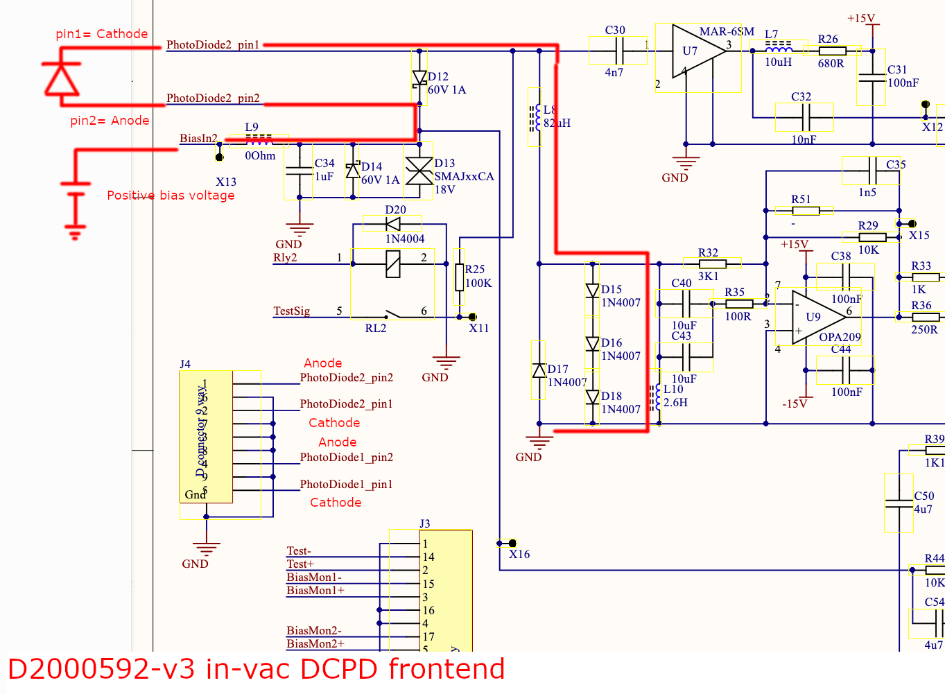
Cable D2300118 (for OMCA): longer is on trans PD, goes to pins 1/2, shorter is on refl PD, goes to pins 4/5
We confirmed that this is the correct wiring according to D2200276
Keita opened up cable D2300119, as this is the cable with incorrect wiring- case was wired to pin 2 and pin 5 instead of pin 6 and 9
We confirmed that the cathode is correctly wired to pins 1 and 4, so we only needed to swap 2/6 and 5/9.
Keita proceeded to switch the pins (this is a very short sentence to describe a long and painful process of removing various peek parts, poking pins through holes and resetting all the peek parts once finished)
Keita reclamped the lower part of the wires and we decided that we should clamp it very tight, as there were no gaps in the clamp on the other cable.
We then swapped the cables, as 118 was incorrectly placed on OMCB and 119 on OMCA. We decided to unscrew the PCB assembly on the back of each tombstone, and then swapped cables, paying attention to which cable went to trans and refl. Note: plugging the PCB assembly back into the DCPD pins is much much easier than inserting the DCPDs from the front.
We then decided to confirm the wiring was correct so we:
- checked that the case of each PD was wired to pins 6 and 9 (pass)
- checked the diode polarity was correct betweens pins1/2 and 4/5 (pass)
- checked that there were no shorts between any of the pins in the cable (failed for cable 119)
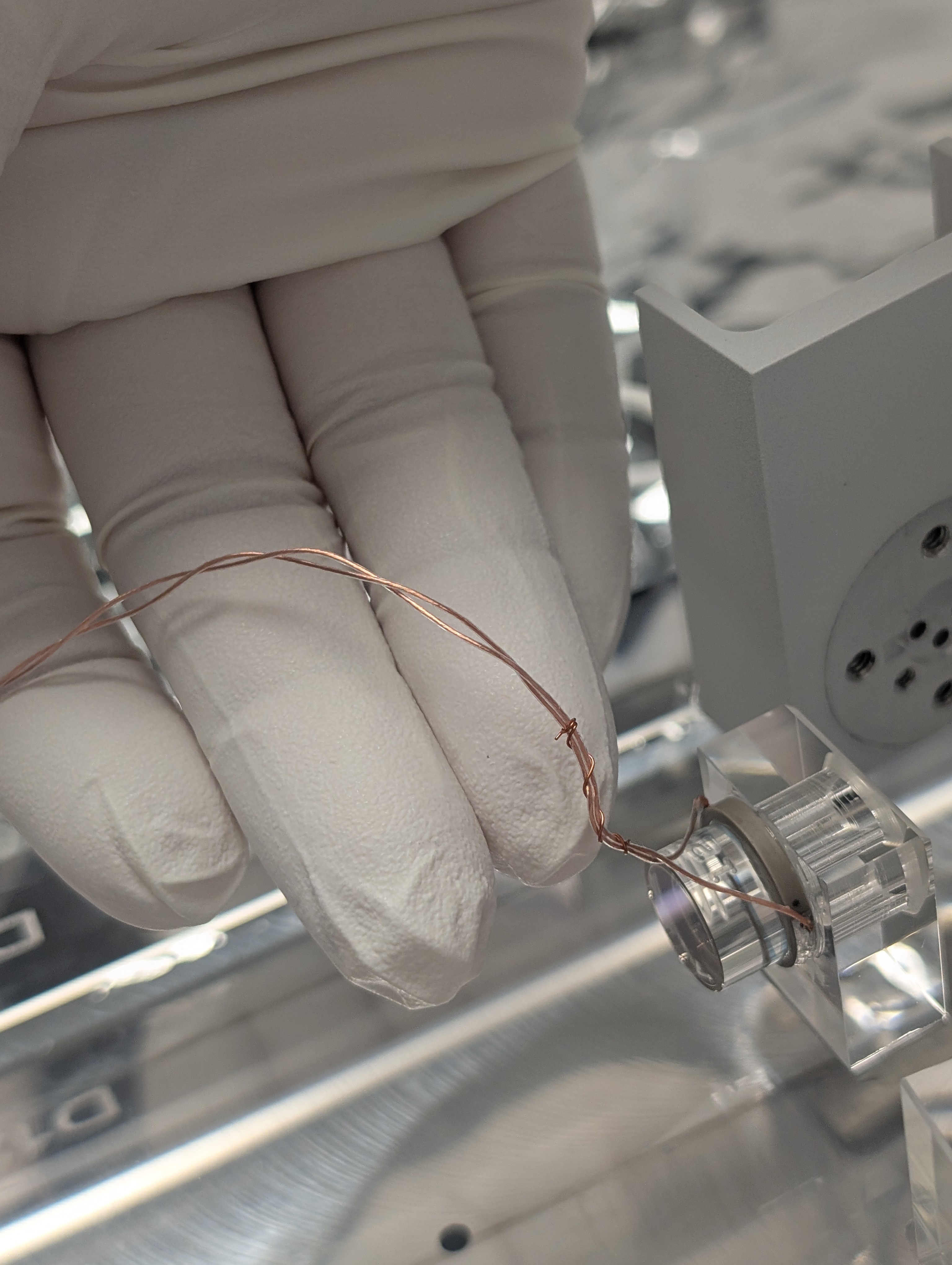
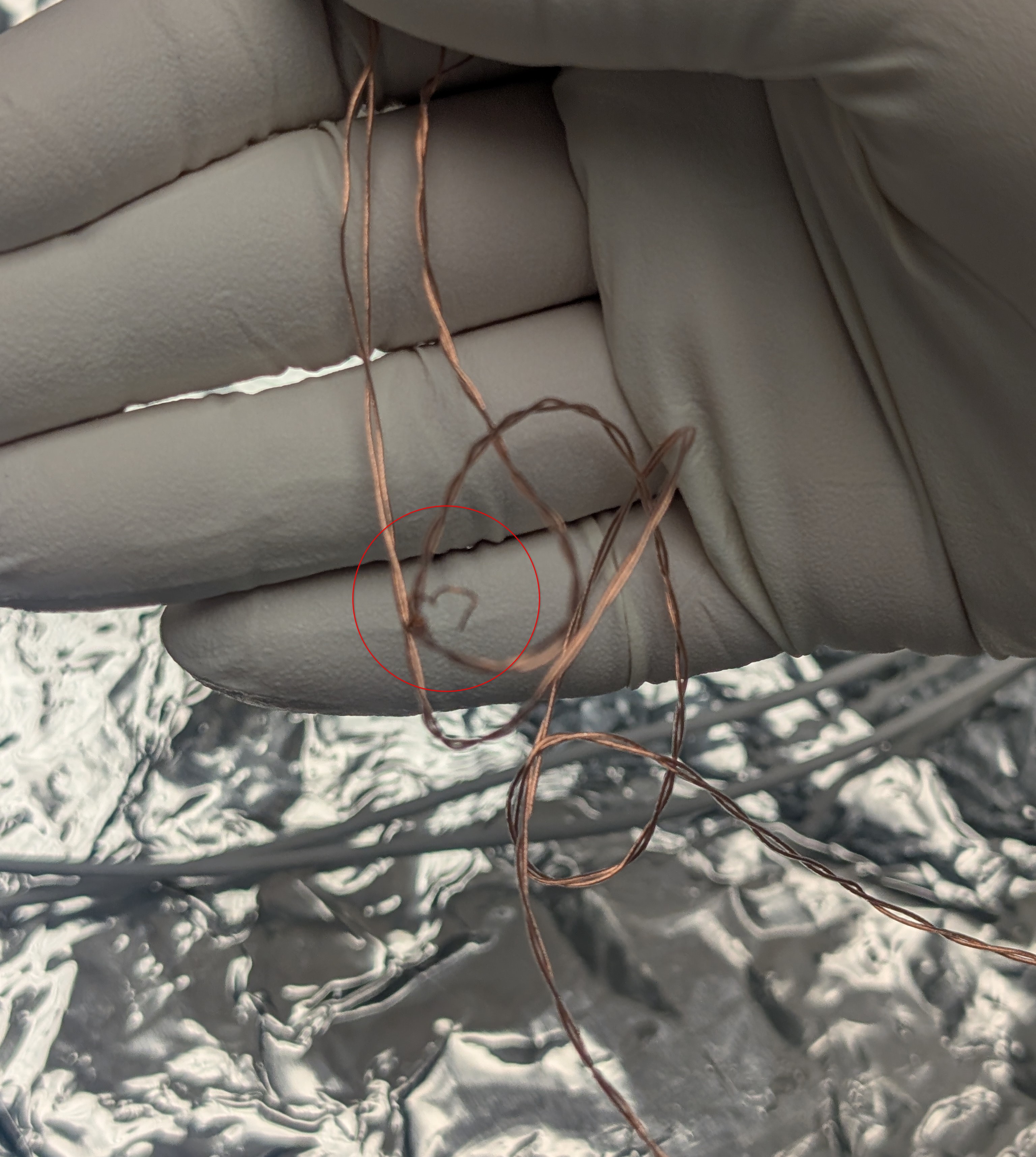
We found a short between pin 3 and 9 on cable 119. We removed the PCB assembly from the back of the DCPD tombstone and checked again, still a short. Keita then removed the lower part of the dsub9 assembly where the wires are clamped, and there was no longer a short between pin 3 and 9. We found one wire that was a bit stripped (see photo), but this was the wire for pin 4, so that didn't explain the problem. We were not able to find anything that could cause short between pin 3 and 9. We decided that maybe the pressure of the clamp caused this problem, so Keita reclamped the wires but less tightly, no more short. We checked one more time for case wiring, polarity, and shorts and all tests passed. Done!


