erik.vonreis@LIGO.ORG - posted 07:16, Tuesday 10 March 2026 (89444)
Workstations were updated
Workstations were updated and rebooted. This was an OS packages update. Conda packages were not updated.
Workstations were updated and rebooted. This was an OS packages update. Conda packages were not updated.
TITLE: 03/09 Eve Shift: 2330-0500 UTC (1630-2200 PST), all times posted in UTC
STATE of H1: Planned Engineering
INCOMING OPERATOR: None
SHIFT SUMMARY:
IMC was locked by sheila/camilla/ryanS. Checks on the BS & PR3 pointing were made. All is set for phasing work out on the floor tomorrow and then moving on to DRMI locking.
LOG:
Sheila, Ryan C, Ryan S, Marc, Daniel, Oli, Control Room...
During the morning, Sheila and Ryan struggled again with the IMC locking. Lots of trending and adjusting gains and signs. The IMC OLG looked noisy and the IMC could stay locked for ~1minute without SUS feedback but not with feedback. The MC1 DAC card was swapped 89426, 89427 and new transfer functions showed this was better than Friday 89435, however IMC still wouldn't stay locked. Daniel, Ryan and Sheila then realized that MC2 M2 was not actuating and Marc and Oli tracked this down to a loose cable 89434, 89436. Oli opened FRS ticket: 37180.
After this was fixed, Sheila started editing the guardian to remove temporary fixes and remeasured the IMC OLG, see attached. This now looks good, 38.5kHz UGF is with 2W into the IMC, gain 5, one common boost on, which is as old guardian would have set it, except M1 feedback is still off. This was compared to 89046 Feb measurements. IM4 trans is 1.2W which is a little lower than before the JAC install.
After the VAC team decoupled the AUX carts by HAM1/2, Jim unlocked the HAM2 HEPI.
Ryan C locked the green arms using INTIAL_ALIGNMENT_OFFLOAD as Jenne reset those references last week 89385.
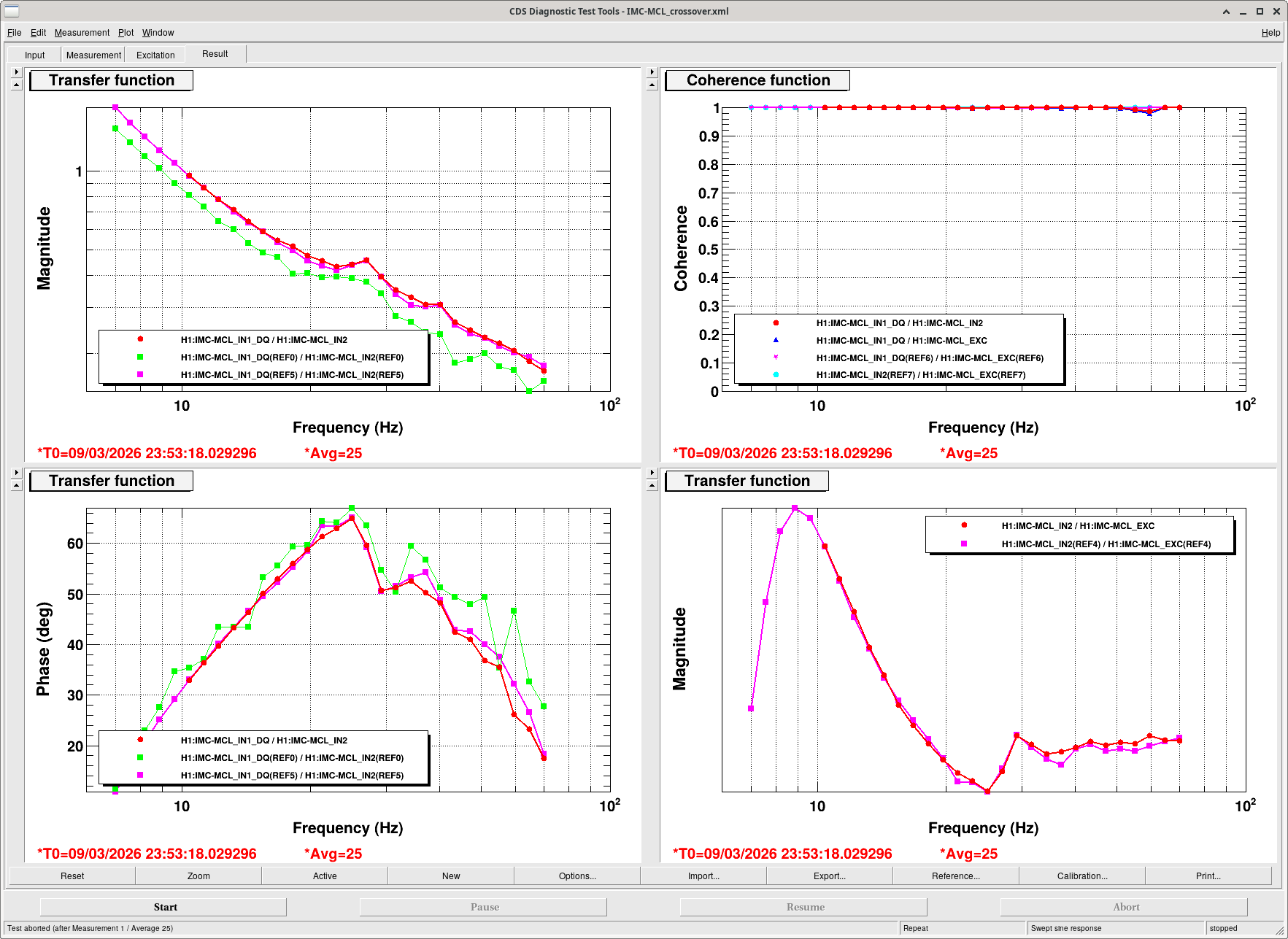
After HAM2 was unlocked, we struggled to turn on the MC2 M2 feedback, however the IMC was surprisingly stable with only the M3 and laser feedback, Sheila took IMC-MCL crossovers. It's a strange loop as M2 isn't really doing anything so Sheila tried copying the PRCL M2 filters over to actuate via M1, this didn't work.
Sheila turned on the IMC WFS, this worked well and brought IMC_TRANS from 180 to 200. Then they were offloaded using the guardian (not the smoothest offloading). After the WFS were offloaded, we reset the guardian to include both M1 and M2 feedback and it worked.
The IMC-MCL crossover was re-measured to be on it's reference, see attached.

The UGf that Camilla posted above (38.5kHz, with 2W input power before JAC and 5dB gain on IMC IN1) implies that the modulation depth for the IMC is about the same or slightly higher than it was before the JAC installation. See 89046 which was before the EOM crystal swap).
After the IMC was locked, Sheila mentioned for tonight there was not alot which could be done (the next steps would be phasing for sensors out on the In-Air Tables, and after that we could move on to locking DRMI). But wanted to look at the BS & PR3 alignment. Before doing that, we did a quick alignment of the Green Arms (to make sure the ITMs were aligned).
While looking at AS_AIR camera the spot was on the camera but off to the right. So, SR2 was moved (mostly in yaw) to get the spot halfway centered on the camera (actually we had two spots here); the BS was used to then get the two spots (one from each arm) on top of each other and centered on the camera. At this point, Sheila mentioned the beatnote looked ok. Sheila also trended PR3 and said its alignment looked good too.
For the night, the rotation stage is will stay at 2W and the IMC is locked. We don't want the PSL to go over 2W, until protections for JAC are in place (trigger PD install on the In-Air JAC/IOT1 table?). And for H1 recovery tomorrow, work will continue for moving on to DRMI locking and beyond.
TITLE: 03/09 Eve Shift: 2330-0500 UTC (1630-2200 PST), all times posted in UTC
STATE of H1: Planned Engineering
OUTGOING OPERATOR: Ryan C
CURRENT ENVIRONMENT:
SEI_ENV state: CALM
Wind: 22mph Gusts, 12mph 3min avg
Primary useism: 0.04 μm/s
Secondary useism: 0.31 μm/s
QUICK SUMMARY:
After a loose cable was secured, IMC work continues by Sheila/Camilla/RyanS. (BHD & Cheta work in labs). Just had a M6.0 EQ off the cloast Naples, Italy!
TITLE: 03/09 Day Shift: 1430-2330 UTC (0730-1630 PST), all times posted in UTC
STATE of H1: Planned Engineering
INCOMING OPERATOR: Corey
SHIFT SUMMARY: The MC1, and IMC/MC2 issues were solved (DAC component swap, and loose cables respectively).
LOG:
| Start Time | System | Name | Location | Lazer_Haz | Task | Time End |
|---|---|---|---|---|---|---|
| 14:56 | FAC | Kim | LVEA | N | Tech clean | 15:30 |
| 15:00 | FAC | Nellie | EndY | N | Tech clean | 15:52 |
| 15:41 | VAC | Jordan | LVEA | N | Aux cart HAM1, YB manifold | 15:49 |
| 15:45 | SEI | Jeff | Optics lab | LOCAL | SPI, laser hazard | 18:31 |
| 16:09 | FAC | Randy | LVEA | N | Biergarten work | 17:12 |
| 16:29 | EE | Marc, Fil | CER | N | Look at MC1 coil drivers | 16:38 |
| 16:47 | EE | Marc, Erik, Rahul | CER | N | DAC swap | 17:07 |
| 17:35 | BHD | Oli, Camilla | Optics lab | LOCAL | BHD optics work | 18:33 |
| 17:51 | EPO | Thomas, Sophie, Jennie | LVEA | N | Tour | 18:10 |
| 17:56 | BHD | Camilla | LVEA | N | Grab dog clamps | 18:01 |
| 18:04 | ISC | Mitch | LVEA | N | West bay parts | 18:17 |
| 18:09 | EE | Sheila, Marc | LVEA | N | Check racks by PSL for MC1 offset | 18:21 |
| 18:25 | FAC | Contractor | MidY | N | Brick unloading | 21:30 |
| 19:26 | ISC | Jennie, RyanS | LVEA/ HAM1 | LOCAL | JAC table work | 21:34 |
| 19:33 | OPS | LVEA is Bifurcated Hazard | HAM1 | LOCAL | LVEA Bifurcated Lazar Hazard | 22:00 |
| 19:59 | SUS | RyanC | CR | N | MC1 TF functions | 20:50 |
| 20:04 | TCS | Sophie | Prep lab | N | Cheeta work | 22:30 |
| 20:44 | SEI | Jeff | Optics lab | LOCAL | SPI work | Ongoing |
| 20:44 | EE | Marc, Oli | CER | N | Check on SUS rack C1 | 21:00 |
| 21:03 | EE | Marc | CER | N | Checking on loose cables, missing screws | 21:39 |
| 21:09 | ISC | Sheila | LVEA | LOCAL | Talk with JAC people | 21:19 |
| 21:28 | VAC | Jordan, Travis | LVEA | N | Decouple aux carts by HAM1/2 | 22:05 |
| 21:40 | EE | Marc | MidY | N | Look for jac screws | 22:03 |
| 21:42 | ISC | Sheila | LVEA | N | Unlock PLS rotation stage | 21:47 |
| 22:02 | SEI | Jim | LVEA | N | Unlock HAM2 HEPI | 22:14 |
| 22:37 | BHD | Oli | Optics lab | LOCAL | BHD work | Ongoing |
| 23:05 | TCS | Sophie, Thomas | Prep lab | N | Cheeta work | Ongoing |
Jennie W, Ryan S
Ryan and I went to the JAC table to align the beam to the wavefront sensors after Daniel corrected (#alog 89413) the ADC channel assignment(#alog 89397) for the WFS DC readouts in the h1ascimc model last Friday.
After some alignment with the WFS A picomotor mirror we realised that the X and Y channels were swapped with pitch corresponding to channel X and yaw corresponding to channel Y.
This happens upstream of the table as the cabling seems correct from the table hookup to the pico.
WFS B is the correct way round.
Both WFS have cross-coupling between pitch and yaw but we were eventually albe to get them aligned just by moving the WFS.
This means the WFS DC channels are hooked to the correct ADC channels in the ascimc model now.
We still need to profile the beam on the table to check the placement of the WFS relative to the beam waist.
We will come back to this tomorrow.
After this we did some lateral movements of the trigger PD to centre it in the beam horizontally but had to stand down because of locking efforts.
The signal cable is not hookled up yet so we can start commissioning this and the shutter once we ge the go ahead from the IFO locking team.

Daniel, Marc, Sheila, RyanC, Camila, Jeff, Oli
MC2 M3 wasn't actuating (89434) and we traced it back to its DAC cable in SUS-C2 U28 card slot #5. The cable was halfway coming off. This is because there were no jack screws to screw the cables into, so over time gravity had been pulling the heavy cable out. We took a couple extra jack screws from an unused port and used them to secure the plug in place. Once we did this, we were able to actuate with MC2 M3 again and we just locked the IMC.
There are many other cables in the CER that aren't properly screwed into their ports. We pressed them in but we will need to add jack screws to them before we have something like this happen again!
FRS ticket: 37180
I ran another set of TFs today for MC1 after the swaps relating to its' DAC in alog89427, they are looking healthy now! The state of the chamber was the same as on Friday, HEPI locked and ISI in Isolated. The SUS was also undamped with alignment offsets off.
/ligo/svncommon/SusSVN/sus/trunk/HSTS/H1/MC1/SAGM1/Data:
2026-03-09_2000_H1SUSMC1_M1_WhiteNoise_L_0p02to50Hz.xml
2026-03-09_2000_H1SUSMC1_M1_WhiteNoise_P_0p02to50Hz.xml
2026-03-09_2000_H1SUSMC1_M1_WhiteNoise_R_0p02to50Hz.xml
2026-03-09_2000_H1SUSMC1_M1_WhiteNoise_T_0p02to50Hz.xml
2026-03-09_2000_H1SUSMC1_M1_WhiteNoise_V_0p02to50Hz.xml
2026-03-09_2000_H1SUSMC1_M1_WhiteNoise_Y_0p02to50Hz.xml
See alog89400 to see the full transfer functions before the coil driver swap, and the Pitch TF after swapping the coil driver (alog89411 for the coil driver swap).
FRS 37167


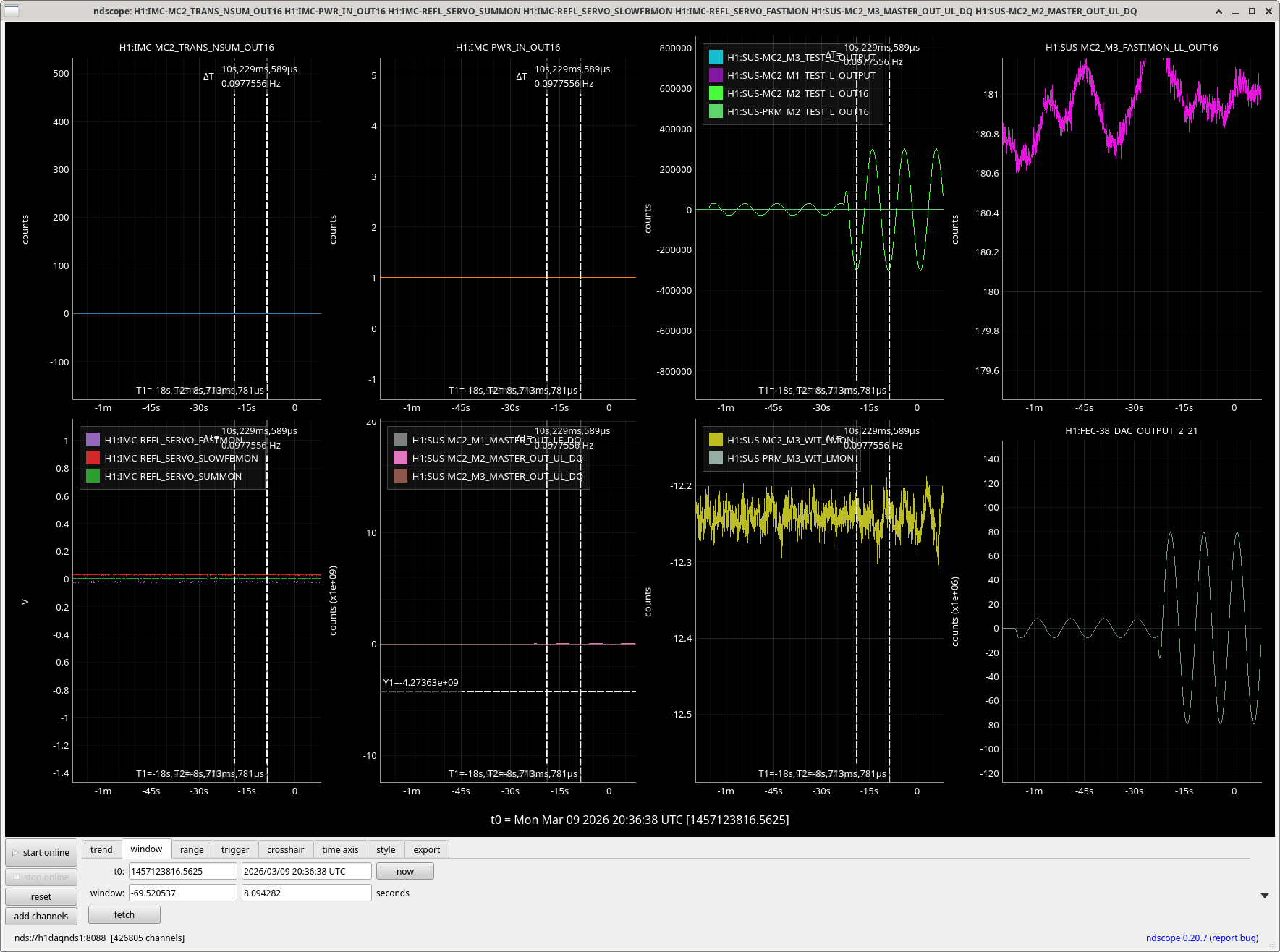
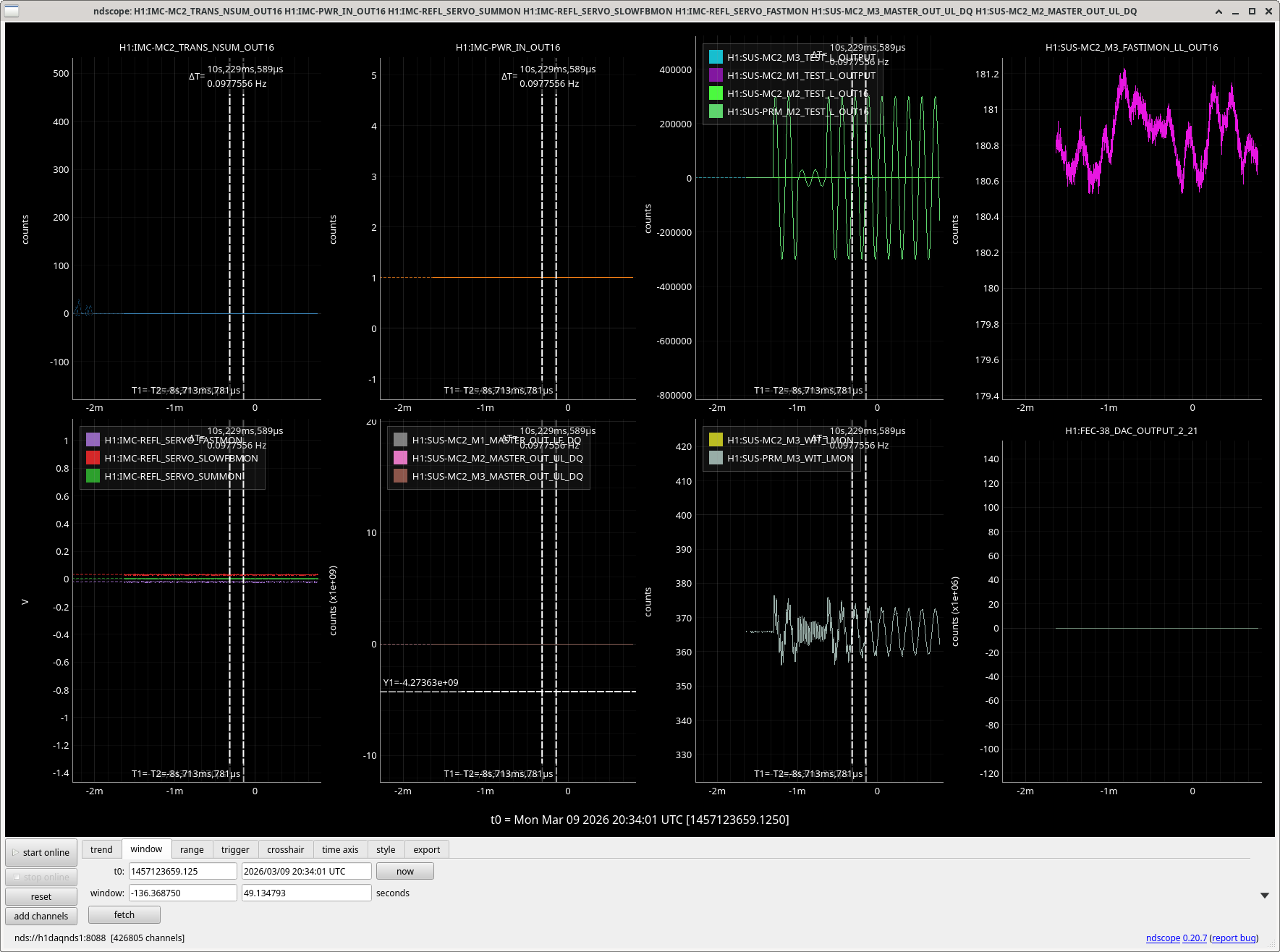
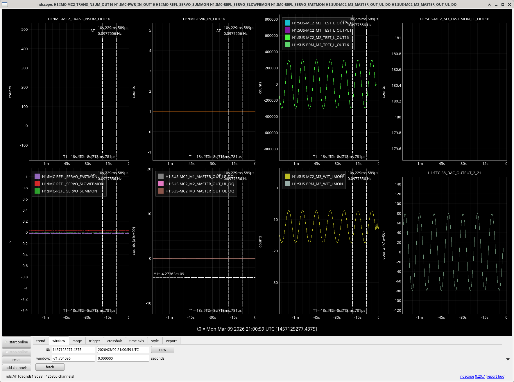
Daniel became suspicous that MC2 M3/M3 may not be actuating. I drove a 0.1Hz line on M1 on MC2, and see it clearly in the M3 L witness (osems).
When driving MC2 M2 with almost the full DAC range (300,000 counts on the test L filter bank), I see no response on M3 witness osems. Repeating this test on PRM the M3 osems see about a 10 um amplitude motion, so it seems that this level of drive should be visible if the suspension was moving.
Edited to add: Marc and Oli found some loose cables, now the actuator on MC2 M2 works.


FAMIS 31128
The PMC HV supply was swapped 6 days ago (alog89349) which took the PMC down briefly. Afterwords, we did some slight PMC alignment and bumped up the pump current for PS4 to get slightly better PMC transmission. The PSL models were restarted on Friday due to timing errors (alog89413), which also briefly took things down, but everything came back without issue.


Mon Mar 09 10:16:12 2026 INFO: Fill completed in 16min 9secs

WP13077 Replace suspect first LIGO-DAC in h1sush12
Sheila, Marc, Erik, Dave:
We replaced the first LIGO-DAC in h1sush12's IO Chassis. Its ribbon cable and interface card were also replaced.
Replacement parts were removed from the DTS x7eetest1 system.
No DAQ restart was required.
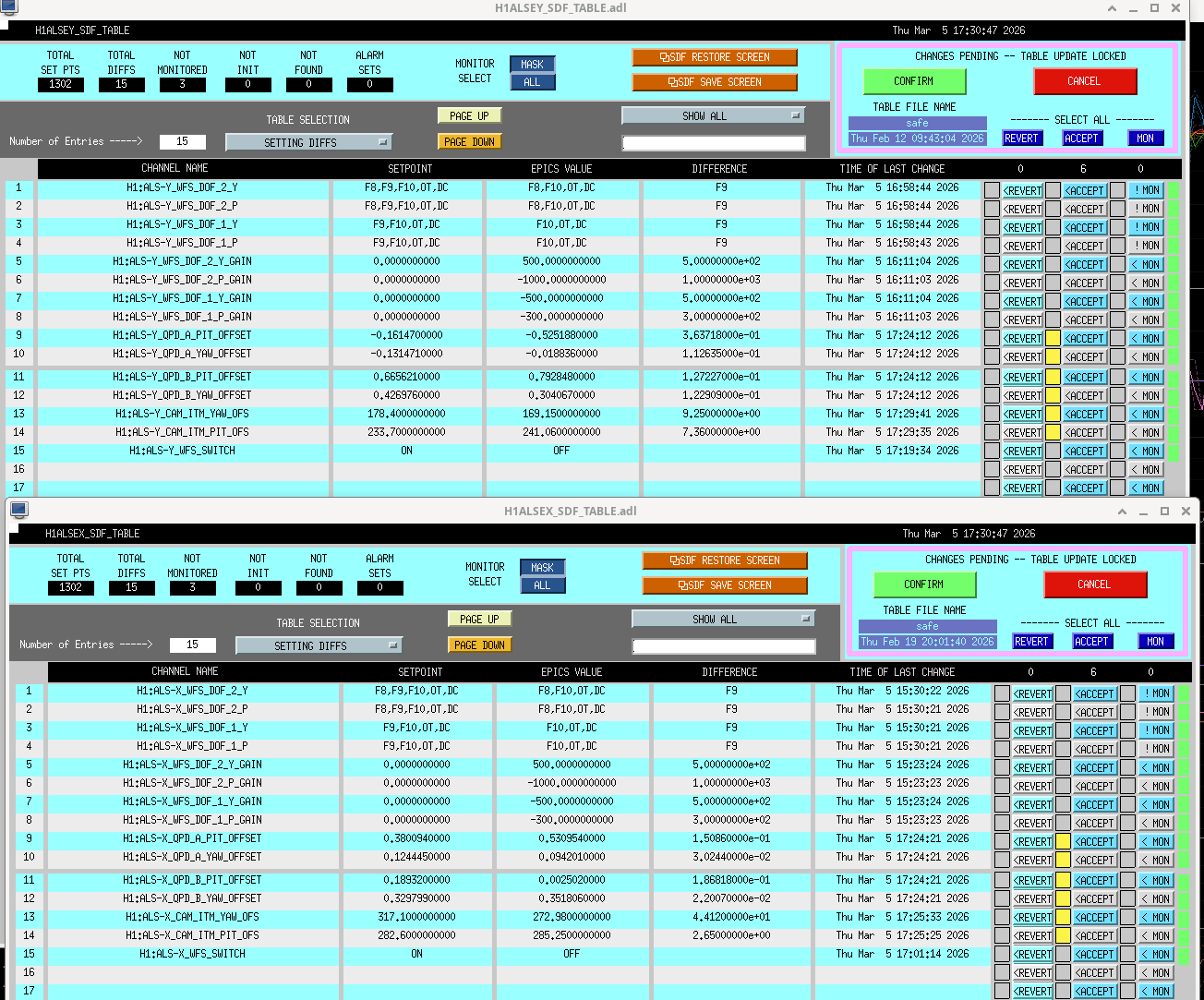
JM1 and JM3 moved after this restart because of some old values in SDF for their alignment sliders, so once things were brought back up, Sheila and I realigned the suspensions and I accepted their alignment offsets in SDF. Screenshot attached.

Old Serial numbers
DAC: S2500460
Interface card: S2500449
New serial numbers:
DAC: S2500445
Interface card: 34924
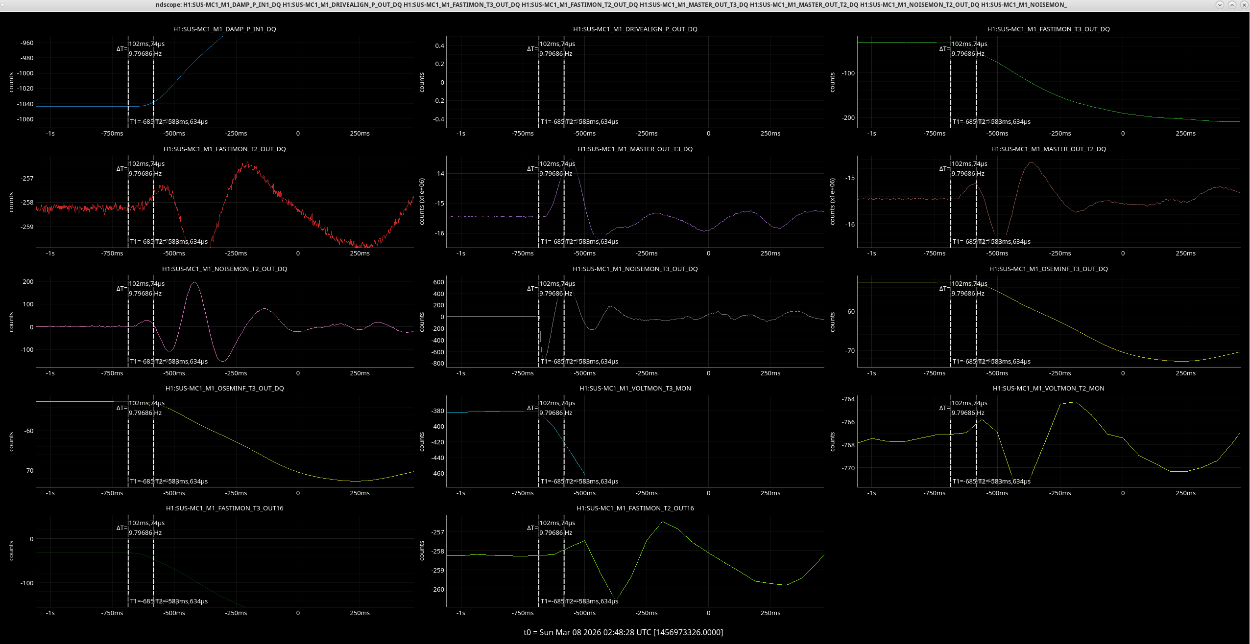
Taking a look at some of the MC1 signals from over the weekend with Sheila and Jeff, we've decided to next swap the DAC card, card 0 on h1susmc1. The OSEMs are moving but not seeing a request in the MASTER_OUT. T3 noisemon seems to see it first.


TITLE: 03/09 Day Shift: 1430-2330 UTC (0730-1630 PST), all times posted in UTC
STATE of H1: Planned Engineering
OUTGOING OPERATOR: None
CURRENT ENVIRONMENT:
SEI_ENV state: CALM
Wind: 4mph Gusts, 1mph 3min avg
Primary useism: 0.02 μm/s
Secondary useism: 0.26 μm/s
QUICK SUMMARY:
Taking a look at the voltmons for T2/T3 of M1 and LL/UR of M2 and M3 I saw there was still some jumping seen in T2 and T3 over the weekend.

[Jenne, Corey, RyanS, Jane Glanzer]
After EE fininished cabling ISCT1 and IOT1, Keita and I put up laser barriers to make the South Bay of the LVEA local laser hazard ("bifurcated"), so that both tables can be opened at will.
Please pay attention to the signs on the laser barriers, and if the barriers are closed and / or the signs show Hazard, then wear laser safety goggles beyond the barriers.
The Vac team opened the gate valves, and we ran the baffle align scripts. After the baffle align scripts completed, I did not touch ITMX again.
Corey and I moved PR3 so that we could see beams on the cameras (we later reverted PR3's sliders), and moved ETMX and TMSX until we had nice TEM00 flashes. We were then able to lock it and run then offload the ETM_TMS_WFS.
With Xarm nicely aligned and PR3's sliders reverted, we had great transmission on ALSX and a familiar looking spot on the camera. However we didn't see anything on the Yarm PD or camera. So, I moved the BS until I could see something (also having increased the exposure of the camera so we could see the straight leakage beam), and then moved ETMY until we started to get flashes. I aligned ETMY and TMSY until we could hold lock on TEM00, and moved the BS until we had ~max transmission on ALSY's transmission PD. We then ran then offload the yarm's ETM_TMS_WFS.
I then (since HAM1 is at much lower pressure than 10 mTorr) opened up the ALS light pipe, and went to check that the alignment on the table looked "reasonable". Indeed, it looks reasonable, in that the PSL beam seems to go nicely through the SHG and is roughly centered on downstream optics. However, we don't have good beatnotes. I had a quick look at the beams headed toward the beatnote PDs, and at least one is easy to see that there are 2 distinct beams headed toward the PD. I don't recall on the top of my head if this is the Diff beatnote though; if it is, then it depends on the BS alignment, so we likely want to hold off on doing any on-table alignment until we have a better idea of the BS alignment relative to the ITMs.
At Sheila's suggestion, I also reset the green initial alignment references (SDF table attached just before accepting them), so that we have an easier time coming back to where we are now. As usual, we'll have to re-reset them after we achieve full 2W lock.
In summary: ITMs were set with the BafflePD script. Green ETM_TMS WFS were run and offloaded. Nothing on IST1 was touched (yet), but it's clear that we'll likely need to do some on-table alignment.
Proposed next steps: Check BS alignment by looking at MICH (so, after JAC is locked, then IMC locked, then XarmIR aligned). Then, consider aligning the ISTC1 beatnotes. Then, lock the whole IFO!
(jenne, ryanS, corey)
NOTES on Green Arm Alignment Recovery After Gate Valves Opened on Mar 5, 2026 for Jenne & Corey (Using Sheila/TJ notes as a reference and adding notes for what was done 3/5/26).
After closing gate valves, alignments tend to shift making recovery harder. In the corner station, the ITM camera pointing will shift enough to make the camera offsets unusable. Sheila posted instructions on how we should recover this in alog88346, detailed below.
= Instructions =
At this point, we were good with green arm alignment!
The HAM1 +Y door was installed today. Installation went smoothly and the O-ring cooperated by staying in place today. I will note that torquing the door bolts is becoming more of an issue due to wrench access being increasingly limited near the 5-way cross/feedthru areas now that all the in-air cables have been attached.
The HAM1/HAM2 annulus system is being pumped by 2 turbos/aux carts on the -Y side of the chambers. The mysterious ~order-of-magnitude pressure readout difference at the two carts on the shared annulus system is again present, as was noted the last time this annulus system was pumped down. Not an issue per se, just some vacuum phenomena that leaves us scratching our heads.
Vent Recovery Update
Annulus ion pumps for HAM1 and HAM2 continue to pumpdown, we closed the isolation valves for both of them, but the ion pumps were not able to maintain pressure. On 3/4/26 valves were opened again to continue using the aux carts, and yesterday (3/5/2026) we isolated the aux cart for HAM2 only, all of that can be seen on the attached plot.
Aux carts will be left pumping and annulus systems are going to be evaluated next Monday.

I isolated the HAM1 aux cart (HAM2 was isolated on Friday) from the annulus this morning. The IP current only rose to ~4.7mA before turning around showing it could hold the annulus pressure.
HAM1/2 annulus aux carts were shut down and decoupled this afternoon. The SS500 cart remains at HAM1 and will continue to pump until the pressure is low enough to valve in the HAM1 ion pump.

