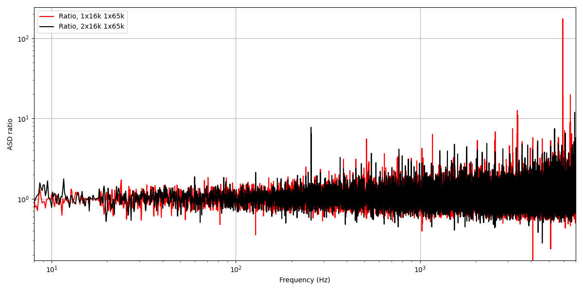
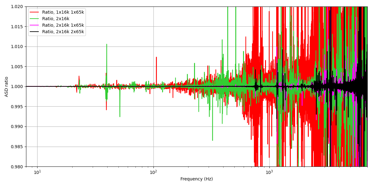
E. Goetz, J. Kissel, L. Dartez In previous aLOGs (see, e.g., LHO aLOG 82405), we had to decimate the 524 kHz data offline in order to evaluate the improvement of TEST channels with changes to anti-alias filtering. We expected to see a reduction in artifacts with the addition of 1 extra 65-16k decimation filter. Attached is a figure showing before and after the ratio of ASDs calculated in DTT from the DCPD A0 channel (not the TEST A channels). This figure shows some improvements (though perhaps hard to see visually) and introduces more questions, especially comparing to a plot like in LHO aLOG 82405, attached here as well. Statistics: Bins above 1% before = 33416 Bins above 1% after = 30273 Bins above 1% before, f < 2000 Hz = 9011 Bins above 1% after, f < 2000 Hz = 8362 Mean before = 1.1087 Mean after = 1.0651 Mean before, f < 2000 Hz = 1.0756 Mean after, f < 2000 = 1.0495 So we do see that the number of bins above 1% has gone down as expected (good), but the raw number of bins above 1% is much different than our expectations. Figure 1 simply seems far noisier than Figure 2. What is the cause of this? It would seem to imply that the IOP downsampling is not simply grabbing 1 value for every 32 samples in a consistent manner, or perhaps the way DTT grabs and exports the PSD data? I'll have to keep digging, but this seems strange
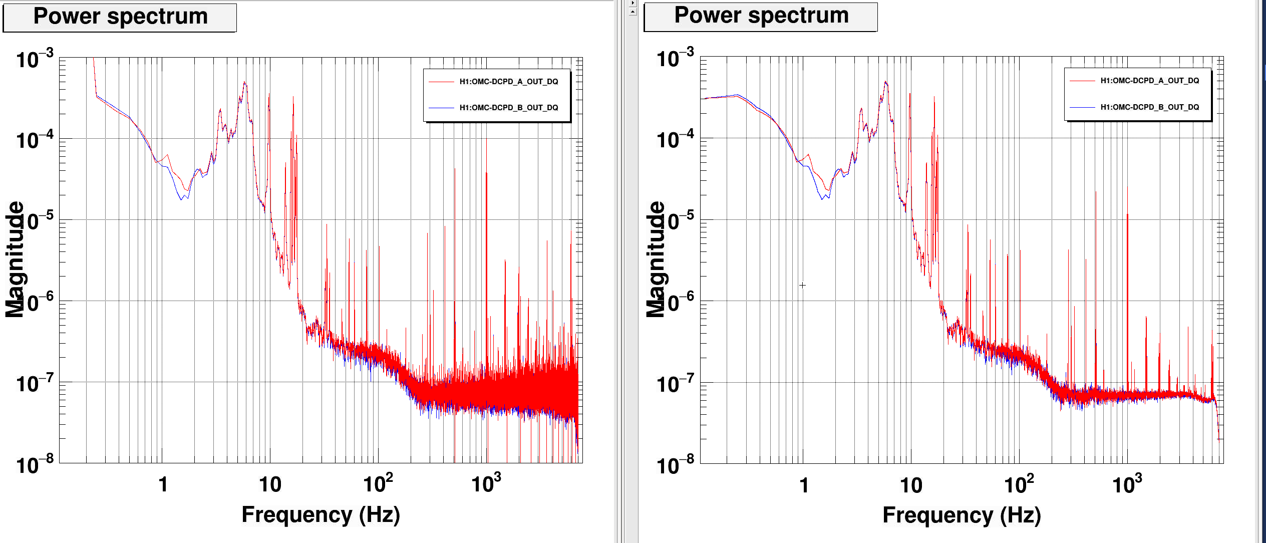
This may be improved by using a the double precision version of diaggui, 'diaggui_test', creates much less noisy ASDs, especially at higher frequencies.
In the attached image, single precision ASD is on the left and double precision is i on the right.
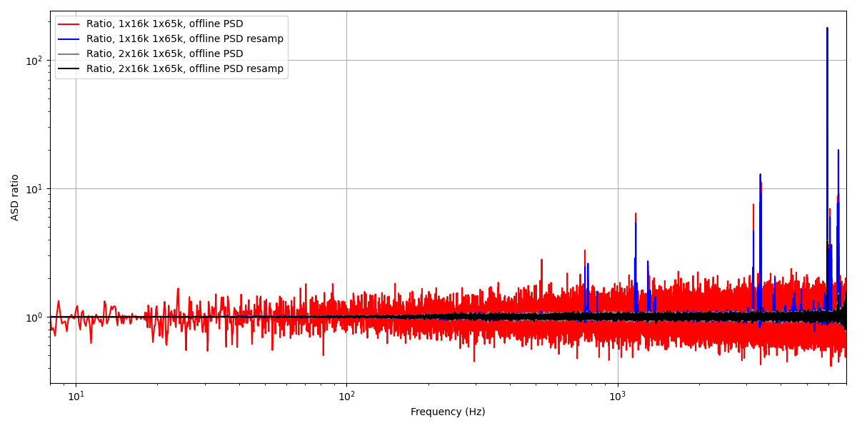
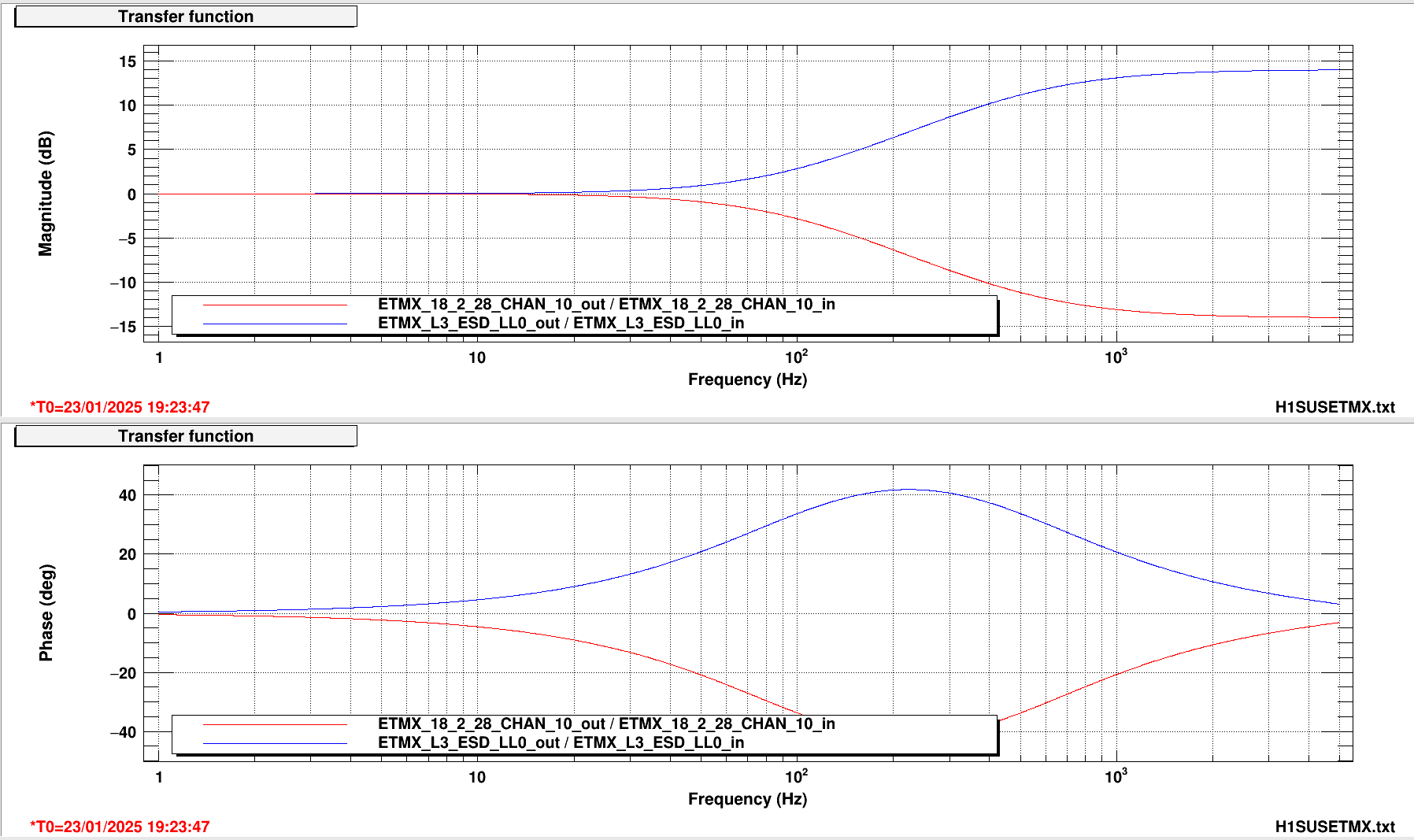
There may be a DTT export precision issue at play here with the ASD as Erik suggests. I wanted to carry out a time series analysis offline, so I exported all of the data before and after for the 16k (H1:OMC-DCPD_A_OUT_DQ) and 524k (H1:OMC-DCPD_A0_OUT) channels. Then I computed the PSD of the 524k channel and 16k channel, plus downsampling the 524k channel and computing the PSD. Then I plot the ratio of the 16k PSD over the 524k PSD (cut off to the 16k Nyquist) to inspect the data for excess noise before and after the addition of the extra 65-16k downsampling filter. I don't understand the red curve, but the blue curve seems reasonable, as well as the black and grey curves. The blue curve shows excess noise that is then suppressed by the additional filter seen in the absence of large ratio values in the black and gray curves. This result shows that the extra filtering is helpful, but until we can push a new calibration, we'll have to hold off adding it in.
I have added whitening and dewhitening filters to the appropriate esd to 28 bit dac filters for the glitch limiting I posted about here. Filters can be accessed from the 28 bit dac test screen called DAC TEST, under the WD tab on the sitemap. Filters aren't engaged, locking has been a challenge this morning and I'm not sure when the filters should be engaged. I also need to try to figure out what the limit should be. I will try to see if we can fit a test in during a commissioning window next week.
Whitening filters are in the L3_ESD_{U/L}{L/R} filters, on the input column of the DAC TEST medm, limits should get applied in those filter banks as well. Dewhitening filters are in the ETMX_18_2_28_CHAN_1/2/3/4 filters in the output row on the bottom of the screen.
Filters I installed are shown in the attached image.
L. Dartez, E. Goetz, J. Kissel, T. Shaffer After we killed the lock stretch by turning on the extra 16 kHz anti-aliasing filter (LHO:82412) -- we found that the OMC wouldn't lock after 4 to 5 attempts during the next lock acquisition attempt. We turned on the 16 kHz AA filter early in the lock acquisition sequence "it would just work" and really -- thinking the cause of the lock loss was the loss of phase margin in the DARM loop. However after seeing the abnormally large number of failed OMC attempts, we suspected the new filter again. Then we realized -- the extra AA filter will cause phase loss at the 4.19 kHz OMC LSC dither line, and thus the OMC LSC DEMOD needs to be rephased to account for it. The magnitude / phase of the 65k to 16kHz AA filter at the 4.19e3 Hz dither line frequency is 1.0837 [ct/ct] / -77.2 [deg]. As such, we adjusted the H1:OMC-LSC_PHASEROT from 56 deg to 56 [deg] - 77 [deg] = -21 [deg], and the OMC "locked right up." (We assume that an 8% increase in the OMC LSC dither line signal would only be *good* for the OMC locking, but this will be confirmed with others later.) We are now in Nominal Low Noise with the extra AA filter on, and have been for 8 minutes (and the many minutes prior that it takes to get from transitioning to DC READOUT and getting to Nominal Low Noise). I've accepted the two changes in the safe and OBSERVE SDFs for the h1omc and h1iopomc0 front-end models.
Screenshots of SDF accepting. h1iopomc0 model's safe and OBSERVE files are linked to the same file, /opt/rtcds/userapps/release/cds/h1/burtfiles/h1iopomc0/safe.snap. h1omc model's safe and OBSERVE files are linked to /opt/rtcds/lho/h1/target/h1omc/h1omcepics/burt/OBSERVE.snap -> /opt/rtcds/userapps/release/omc/h1/burtfiles/h1omc_OBSERVE.snap /opt/rtcds/lho/h1/target/h1omc/h1omcepics/burt/safe.snap -> /opt/rtcds/userapps/release/omc/h1/burtfiles/h1omc_down.snap
Thu Jan 23 10:11:46 2025 INFO: Fill completed in 11min 43secs
Gerardo confirmed a good fill curbside. TCmins [-79C,-77C] OAT (0C,32F). delta-temp trip 10:11:53
J. Kissel, E. Goetz, L. Dartez The lock loss at 2025-01-23 16:41:17 UTC (08:41 PDT Thursday morning) was a a result of our first attempt to turn ON the additional 65k to 16k digital AA filter (see LHO:82404 and references therein). Out of the utmost precaution we (via command line) performed what we do all the time (via script) for a analog whitening filter change: - via command line, ramped all DARM error signal over to DCPDB by simultaneously changing the gain the 16 kHz filter banks (H1:OMC-DCPD_A_GAIN and H1:OMC-DCPD_B_GAIN) from A:1.0 and B:1.0 to A:0.0 and B:2.0 with a ramp time of 10 seconds. - switched ON the second copy of the 65k to 16k "Dec16k" filter in FM10 in the 524 kHz filter bank for A, H1:OMC-DCPD_A0 - command line ramped all DARM error over to DCPDA, from A:0.0 and B:2.0 to A:2.0 and B:1.0 with a ramp time of 10 seconds... ... and it was most of the way through that 10 second ramp back to the new filter configuration of DCPDA that we lost lock. We're going to try again, but this time have the new AA filter configuration on already during lock acquisition.
TITLE: 01/23 Day Shift: 1530-0030 UTC (0730-1630 PST), all times posted in UTC
STATE of H1: Observing at 156Mpc
OUTGOING OPERATOR: Ibrahim
CURRENT ENVIRONMENT:
SEI_ENV state: CALM
Wind: 12mph Gusts, 10mph 3min avg
Primary useism: 0.02 μm/s
Secondary useism: 0.19 μm/s
QUICK SUMMARY: Locked for almost 3 hours, two auto relocks over night. No alarms this morning. Planned commissioning and calibration this morning from 1630-2000UTC.
TITLE: 01/23 Eve Shift: 0030-0600 UTC (1630-2200 PST), all times posted in UTC
STATE of H1: Observing at 155Mpc
INCOMING OPERATOR: Ibrahim
SHIFT SUMMARY:
H1 has been locked and Observing for just under 8 hours.
It's been a quiet night.
No locklosses, but No events either though.
Looking for the latest In-Lock Sus Charge files i find that last ones were made on Jan 7th and already alogged 82163 .
cdsws25: ls /opt/rtcds/userapps/release/sus/common/scripts/quad/InLockChargeMeasurements/rec_LHO -lt | head -n 6
total 527
-rw-r--r-- 1 test_user controls 160 Jan 7 07:58 ETMX_12_Hz_1420300733.txt
-rw-r--r-- 1 test_user controls 160 Jan 7 07:50 ETMY_12_Hz_1420300262.txt
-rw-r--r-- 1 test_user controls 160 Jan 7 07:50 ITMY_15_Hz_1420300244.txt
-rw-r--r-- 1 test_user controls 160 Jan 7 07:50 ITMX_13_Hz_1420300243.txt
-rw-r--r-- 1 test_user controls 160 Dec 17 07:58 ETMX_12_Hz_1418486333.txt
Since I thought I remember us being locked this past Tuesday morning I checked to see if the SUS_Charge Guardian ran and it looks like it didn't run, but we were actually locked?
I don't see a reason why it wouldn't have run. It looks like since the h1guardian1 machine reboot ont he 14th it hasn't run. Looking at the code it wait for exactly 07:45:00 PT. Maybe it missed that exact second for some reason? That said, the EXECTIME channel for that node shows 0, so I would expect it to catch that second. I've reran SUS_CHARGE through INIT and we'll see if it does it next Tuesday. If not, perhaps we change this to have a >1 second buffer on start time.
TITLE: 01/23 Day Shift: 1530-0030 UTC (0730-1630 PST), all times posted in UTC
STATE of H1: Observing at 154Mpc
INCOMING OPERATOR: Tony
SHIFT SUMMARY: Planned commissioning time today that focused on a PR2 spot move. There was a lock loss during this spot move and we decided to revert the move. Recovery was a bit challenging, but pico hysteresis or similar could be the cause. Read more below. One side effect of the picoing from the PR2 move, is that the ALS camera spots are slightly different. Some of the clipping that we would see on ALSY is no longer there and ALSX now has some in the top left corner.
LOG:
Start Time | System | Name | Location | Lazer_Haz | Task | Time End |
---|---|---|---|---|---|---|
17:16 | SAFETY | LAZER HAZ (\u2310\u25a0-\u25a0) | LVEA | !!!YES!!! | LVEA = LASER HAZARD! | 16:51 |
16:01 | FAC | Kim | Opt Lab | n | Tech clean | 16:24 |
16:33 | PEM | Robert | LVEA | yes | Viewport beam spot measuring | 17:26 |
18:42 | FAC | Kim | MX | n | Tech clean | 19:30 |
19:02 | VAC | Janos, tourer | EX, MX | n | Tour | 20:51 |
19:30 | PEM | Robert | LVEA | yes | Closing up viewports | 20:00 |
21:25 | PCAL | Tony | PCAL Lab | local | PCAL lab work | 23:50 |
23:31 | ISS | Keita, Rick, Jennie, Mayank, Sivananda | Opt Lab | n | ISS array |
|
TITLE: 01/23 Eve Shift: 0030-0600 UTC (1630-2200 PST), all times posted in UTC
STATE of H1: Observing at 155Mpc
OUTGOING OPERATOR: TJ
CURRENT ENVIRONMENT:
SEI_ENV state: SEISMON_ALERT
Wind: 2mph Gusts, 1mph 3min avg
Primary useism: 0.04 μm/s
Secondary useism: 0.20 μm/s
QUICK SUMMARY:
All systems seem to be working well. (Execpt that Dust monitor)
Just transitioned into Earthquake mode for a 5.8 M earthquake, hopefully we can ride it out.
Sheila, Jenn{e,ie}, Robert
Continuing efforts to find out how to minimise the beam from PR2 clipping on the scraper baffle, as investigated in alogs #[77870, 77968, 77988, 81329].
At the start Sheila and Jenne agreed we should try to find the two extrema where the beam going from PR2 to PR3 clips the scraper baffle and the one going from PRM to PR2 clips the scraper baffle.
Sheila measured the PR2 Y2L gain by minimising the transfer function from PR2 yaw position to PRCL_OUT, while injecting a line at 30Hz as in [LHO alog #82251] entry.
New P2L: -0.36 from the measurement I did the other week.
New Y2L: -6.25
Now the aim was to move the spot on PR2 to find where each beam hitting it clips the PR2 scraper baffle.
Move PR3 in negative yaw while monitoring LSC-POP_A_LP_NORM (pop power) and PR2 inmon on M1 to check ASC is not changing much to ensure we do not unlock the IFO. Every 13 PR3 microradians is 0.5mm.
We stepped 96 uradians to 68 microradians on PR3 yaw and corrected pitch down every time we dipped too low on LSC-POP or PWR_CIRC, every 1 microradian or so jenne moved picomotor A_8 (the one that aligns to both the ALS PDs and the LSC-POP PDs) by -50 counts to bring back the LSC POP alignment.
I measured our new Y2L to be -5.75 gain at this new value (moved 1 mm according to Jenne's script). Robert looked at the beam reflected off the baffle to the viewport at this point as a check of the power in it relative to our nominal position for the PR2 beam spot.
We kept going after this point but lost lock after moving about 8.5 microradians.
ETMX glitch, and it looks like it was glitching for a tens of seconds before we lost lock - shot from lock lost tool.
Interestingly, ALSX was having issues staying locked after this lock loss. See attached for an example.
L. Dartez, E. Goetz, J. Kissel Yesterday's test results and plots show that (a) Installing one additional copy of the existing 65 kHz to 16 kHz "Dec16k" filter improves the 20-2000 Hz band aliasing dramatically, where as that *and* one additional copy of the 524 kHz to 65 kHz "Dec65k" filter does not significantly improve the 20-2000 Hz band aliasing (but one copy is still required). See LHO:82405 (b) We have (just barely) enough phase margin in the DARM loop to install more digital anti-aliasing. (I plan to make better plots today, but see page 1 of 4th attachment of LHO:82387) (c) We have (just barely) enough CPU clock-cycle turn-around time to install a few more filters (see 2nd attachment of LHO:82375). If this proves problematic, we can start clearing out test filters to claw back computation time. As such, we plan to move forward with installing an additional 65k to 16 kHz "Dec16k" filter in the primary GW-channel, 524 kHz, DCPD A0 and B0 banks tomorrow. We happen to be unlocked now, so I've staged (loaded in, installed, but NOT turned off) the new additional filter in the A0 and B0 bank into the H1IOPOMC0.txt foton file. While there, I took the time to improve the name and clarity of the A0 and B0 filter banks, much like I've done in the A1, A2, B1, B2 test banks (in LHO:82313), - Renamed "NewV2A" and "NewAW" in the A0 and B0 banks -- which are *different* filters, to compensate for the *different* analog electronics in those PDA and PDB chains -- to . "PDA_V2A" and "PDA_AW" . "PDB_V2A" and "PDB_AW" - Split out the gain that was in "cts2V" = gain(0.0006105)*gain(0.25)*gain(0.25) into two banks "18b_cts2V" and "sum4avg" . For the "18b_cts2V" gain, even though gain(0.0006105)*gain(0.25) = gain(0.000152625) which DOES NOT equal the "right" gain of 40/2^18 = 0.000152587890625, (a ratio of 1.0002432, or 0.24% different). In the spirit of moving stuff around without changing anything I installed the a gain(0.000152625) for now. Also, at the 0.24% level, the channel to channel gain is probably different anyways, and comes out to some make-shift value anyways in the 4-channel averaging. The "not right" gain comes from the typo of 40/2^16 = 0.0006103515625, which was installed as 0.0006105. . The "sum4avg" is the gain(0.25) you would expect to turn the sum of 4 channels into an average. - Moved the "18b_cts2V" , "sum4avg" and "A2mA" gains to be in FM3, FM4, and FM5 - Such that now there's a "Dec65k" in FM8, and two copies of "Dec16k" in FM9 and FM10. Also -- since the H1:OMC-PI_DOWNCONV_INMTRX matrix is configured to use only DCPD A, I made similar changes OMC PI DOWNCONV SIG bank, except -- in tthe event we ever need to switch the sig bank over to DCPD B, I installed the "PDB_V2A" and "PDB_AW" filters there as well. See attached screenshots. (1st) Screenshot of the A0 and B0 banks *before* any changes were made (2nd) Screenshot of the A0 and B0 banks *after* the changes described above were made. NOTE that FM10 is turned OFF. (3rd) Screenshot of the OMC PI DOWNCONV SIG bank *after* the changes. (4th) Screenshot of SDF accept of new arrangement of A0 and B0 filters. (5th) Screenshot of SDF accept of new arrangement of OMC PI DOWNCONV SIG filters. The updated filter file is commited to /opt/rtcds/userapps/release/cds/h1/filterfiles/H1IOPOMC0.txt rev 30480 The updated safe.snap (which is linked to both the safe.snap and OBSERVE.snap) has been committed to /opt/rtcds/userapps/release/cds/h1/burtfiles/h1iopomc0/safe.snap rev 30481
As noted in LHO aLOG 82394, I recommend starting improvements by adding an additional 16k downsampling filter. Attached is a figure showing a comparison of the current situation (red), just 2 16k filters (green), 2 16k filters and 1 65k filter (magenta), and 2 16k filters and 2 65k filters (black). The curve colors are the same as the original FOTON plots in LHO aLOG 82375. These curves are ratios of PSDs using different downsampling filters on the time series data that is manually downsampled by a factor of 32 (524k ==> 16k) versus PSD of the original 524k data (cut off with the maximum frequency of 8192 Hz). The narrow instrumental artifacts are visible by eye in the 8 s FFTs of the DTT measurements, and are much more visible in the CW analyses that use longer coherence times. We can quantitatively assess the improvement by comparing the number of bins in this short analysis that are 1% in excess of the nominal ratio of 1: Full band: 16k 65k bins above 1% = 14847 16k 16k bins above 1% = 6686 16k 16k 65k bins above 1% = 4892 16k 16k 65k 65k bins above 1% = 4809 0 - 2 kHz band: 16k 65k bins above 1% = 430 16k 16k bins above 1% = 21 16k 16k 65k bins above 1% = 0 16k 16k 65k 65k bins above 1% = 0 Note that even though the 2 kHz band has only a few hundred bins above 1%, these artifacts are strongly visible in run-averaged spectra that use longer coherent baselines, similar to all-sky CW searches. One can see that the additional 16k filter does most of the clean up (we don't see a significant change by an extra 65k filter). By employing an additional filter, this should hopefully reduce or eliminate the impact of the narrow instrumental artifacts.
Wed Jan 22 10:03:51 2025 INFO: Fill completed in 3min 48secs
Gerardo confirmed a good fill curbside. TCmins [-78C, -60C] OAT (-1C, 30F)
TITLE: 01/22 Day Shift: 1530-0030 UTC (0730-1630 PST), all times posted in UTC
STATE of H1: Observing at 154Mpc
OUTGOING OPERATOR: Ryan S
CURRENT ENVIRONMENT:
SEI_ENV state: CALM
Wind: 3mph Gusts, 2mph 3min avg
Primary useism: 0.02 μm/s
Secondary useism: 0.25 μm/s
QUICK SUMMARY: Locked for 12 hours, useism dropped quickly overnight. Planned commissioning time this morning.
TITLE: 01/22 Eve Shift: 0030-0600 UTC (1630-2200 PST), all times posted in UTC
STATE of H1: Observing at 154Mpc
INCOMING OPERATOR: Ryan S
SHIFT SUMMARY:
One lockloss and a successful return to Observing at 3:43 UTC.
Otherwise a quiet night.
LOG:
No Log
Bright beam spot on HAM3 ballast mass baffle moves with ITMY compensation plate yaw motion
We have been looking for the source of the scattering noise that varies with the ITMY compensation plate yaw setting (80499). I recently searched for beam spots in the HAM3 area that move as CPY is yawed, using movies that I took from both the MC2 camera viewport and the PR2 camera viewport near HAM2. Anamaria and I had done some of this before (77631) but this time I recorded the CP movements on the audio track of the movies for a more precise correlation. And I also modified the movies in iMovie to increase visibility of faint spots. Figure 1 shows that I did find a spot that moved precisely with CPY Yaw settings (link to movie clips: https://youtu.be/FDdNDPoQadU ). The spot appears to be on a ballast mass baffle (see Fig. 1), which is not angled as much as the scraper baffle (which I think the beam is supposed to fall on (Alena's slides)) and may thus retroreflect more light.
Mystery beam spot on HAM3 spool piece comes from ITMX direction, not HAM2 direction
I had previously misinterpreted the pattern of light on edges and bellows of the HAM3 spool piece as suggesting that the mystery beam spot (78192) was coming from the HAM2 direction . More recently I found that there was light on the HAM3 side of the MC baffle that had a similar interference pattern and was consistent with being part of the mystery beam spot (Figure 1). The light on the HAM3 side of the baffle was visible when looking through the viewport for the PRM camera at a high angle. Thus, the beam is most likely coming from the ITMX direction, travelling close to the –Y wall of the beam tube.
One possibility is that it actually comes from ITMX, either scattered light from ITMX or scattered light from the back side of MC2 reflecting off of ITMX. Figure 3 shows these suggested paths and a picture taken from the point of view of the beamspot on ITMX that shows that there is a clear path to the site of the mystery beam spot. I think that the cartoon shows that it would be worth using a real model to determine if these paths are possible.
I checked to see if the beamspot on the eye baffle moved or modulated when I actuated the compensation plates. I made movies as I moved the two compensation plates more than 600 microradions in pitch and yaw, but, unlike the spot on the ballast mass baffle, I did not see any modulation or motion of the spot on the eye baffle.
Somehow I used the wrong photo in Figure 3 - it is actually a photo from the beamsplitter. The correct photo from CPx is used in the corrected version of Figure 3 attached here.