Displaying reports 461-480 of 88291.Go to page Start 20 21 22 23 24 25 26 27 28 End
Reports until 18:17, Monday 01 June 2026
H1 SEI
arnaud.pele@LIGO.ORG - posted 18:17, Monday 01 June 2026 (90429)
CRS progress log

Jim, Shoshana, Alexandra, Arnaud

Today we continued setting up the H2-PSL lab to start the testing the HOQIs.

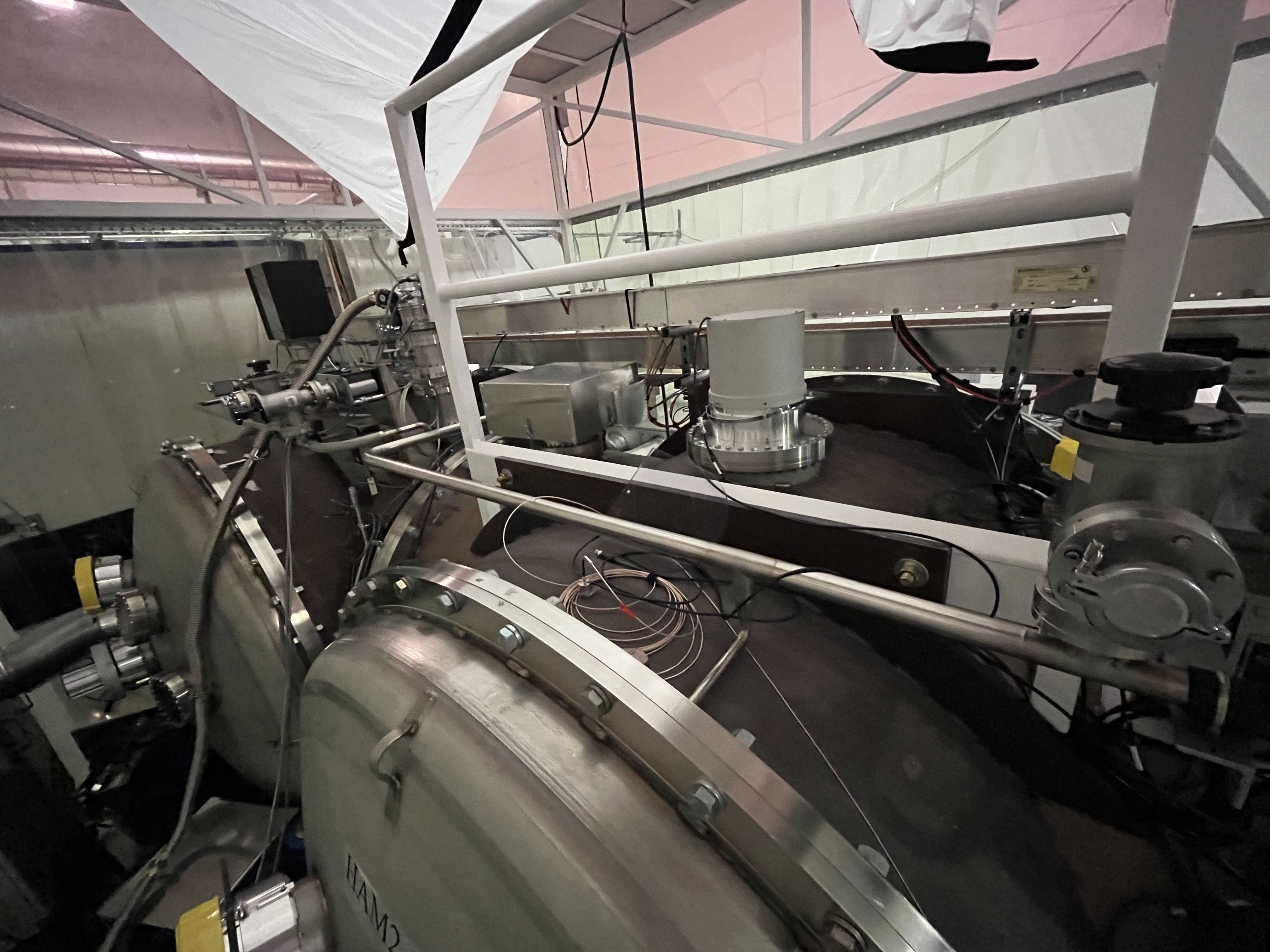
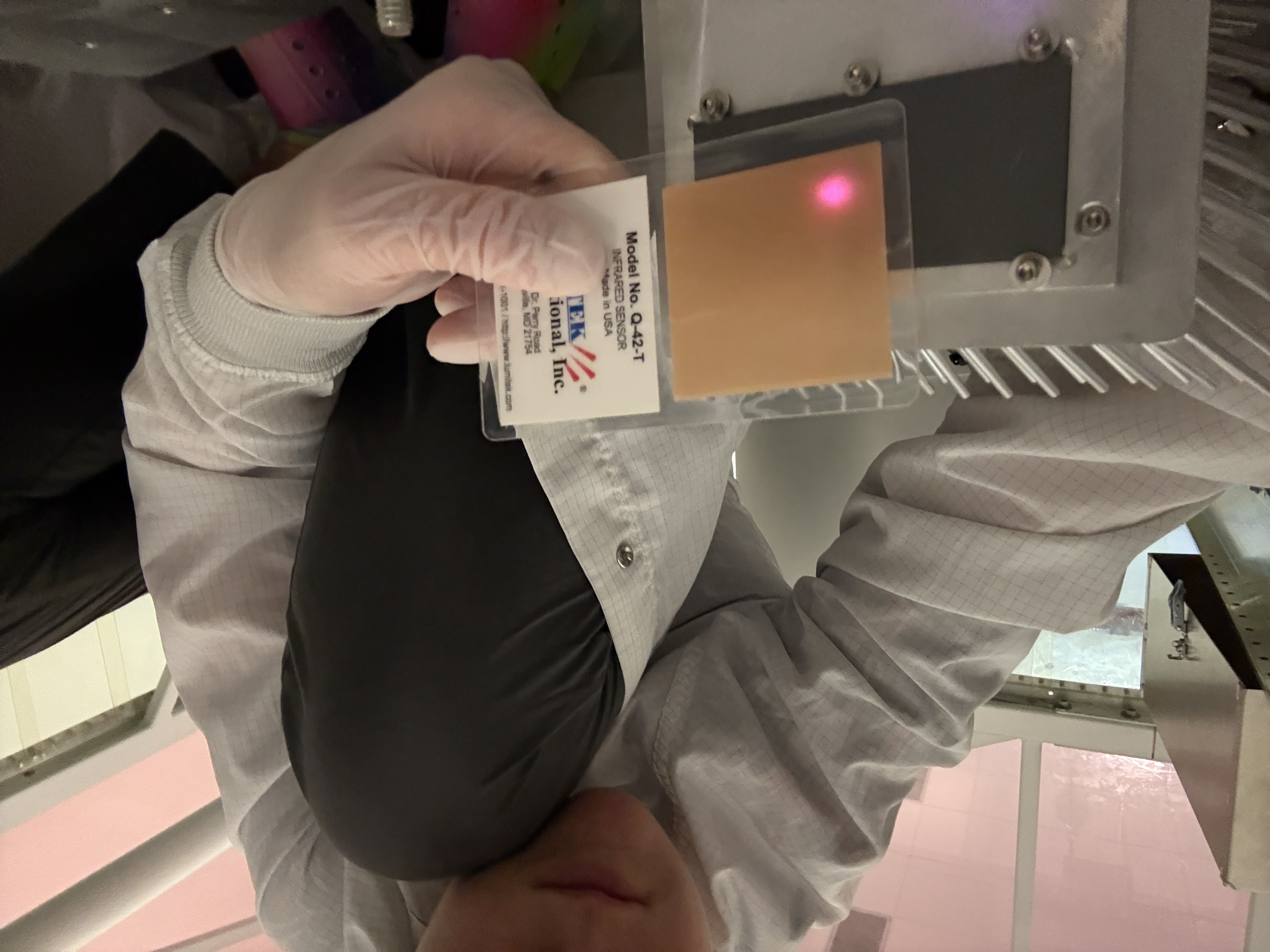
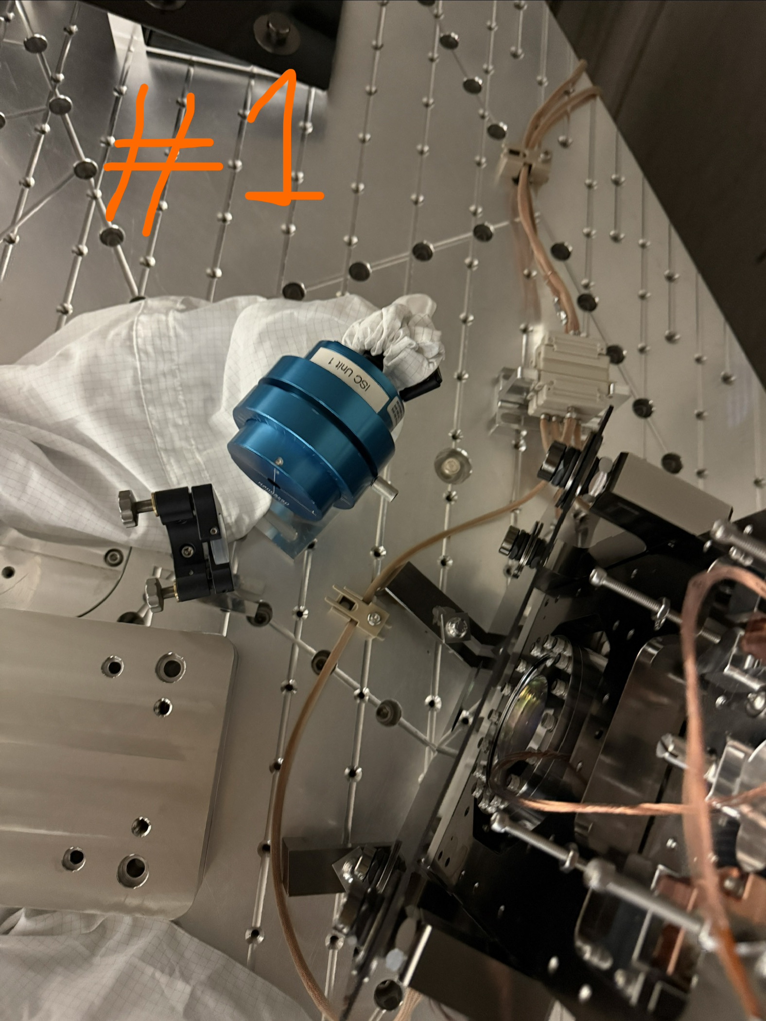
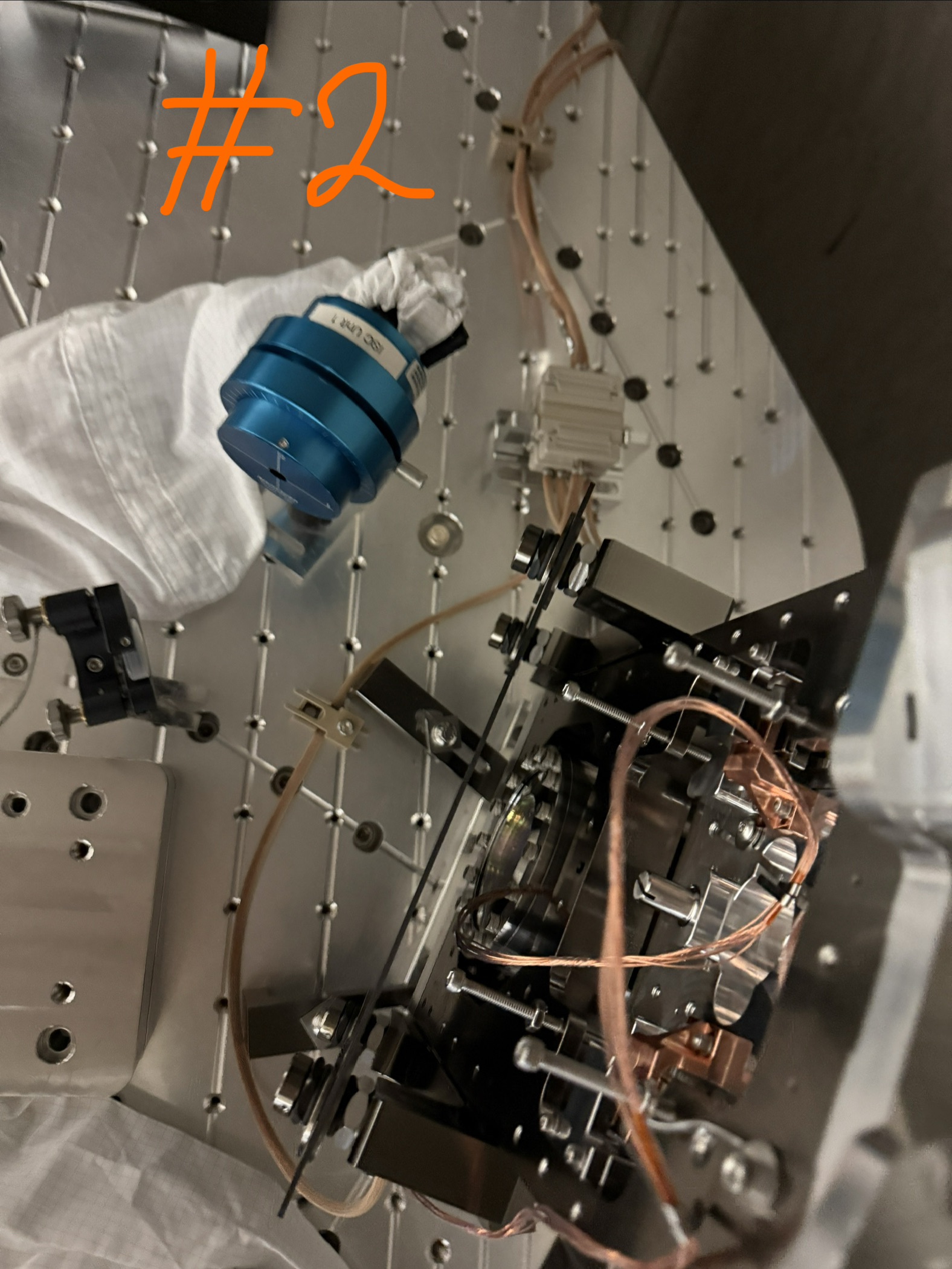
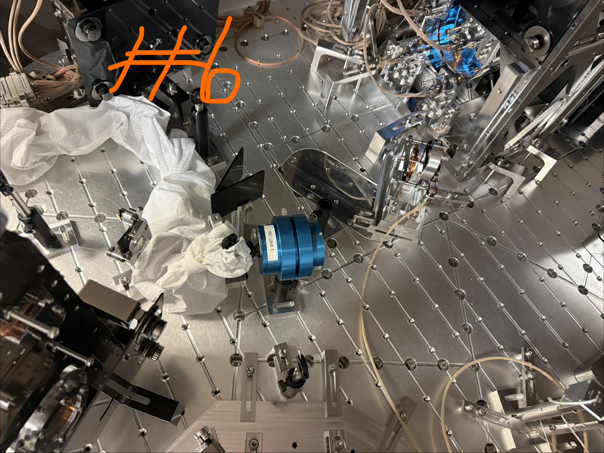
* Received and moved the laser system (RIO+Laser Driver+TEC), and readout (HOQI TIA) in the H2-PSL (see picture 1) 
* Gathered needed electronics from the EE shop (See list below) and plugged them in the lab
* Bagged and tagged the peek HOQI components from VPW (waveplate holders, photodiode holders, in-vac cables)
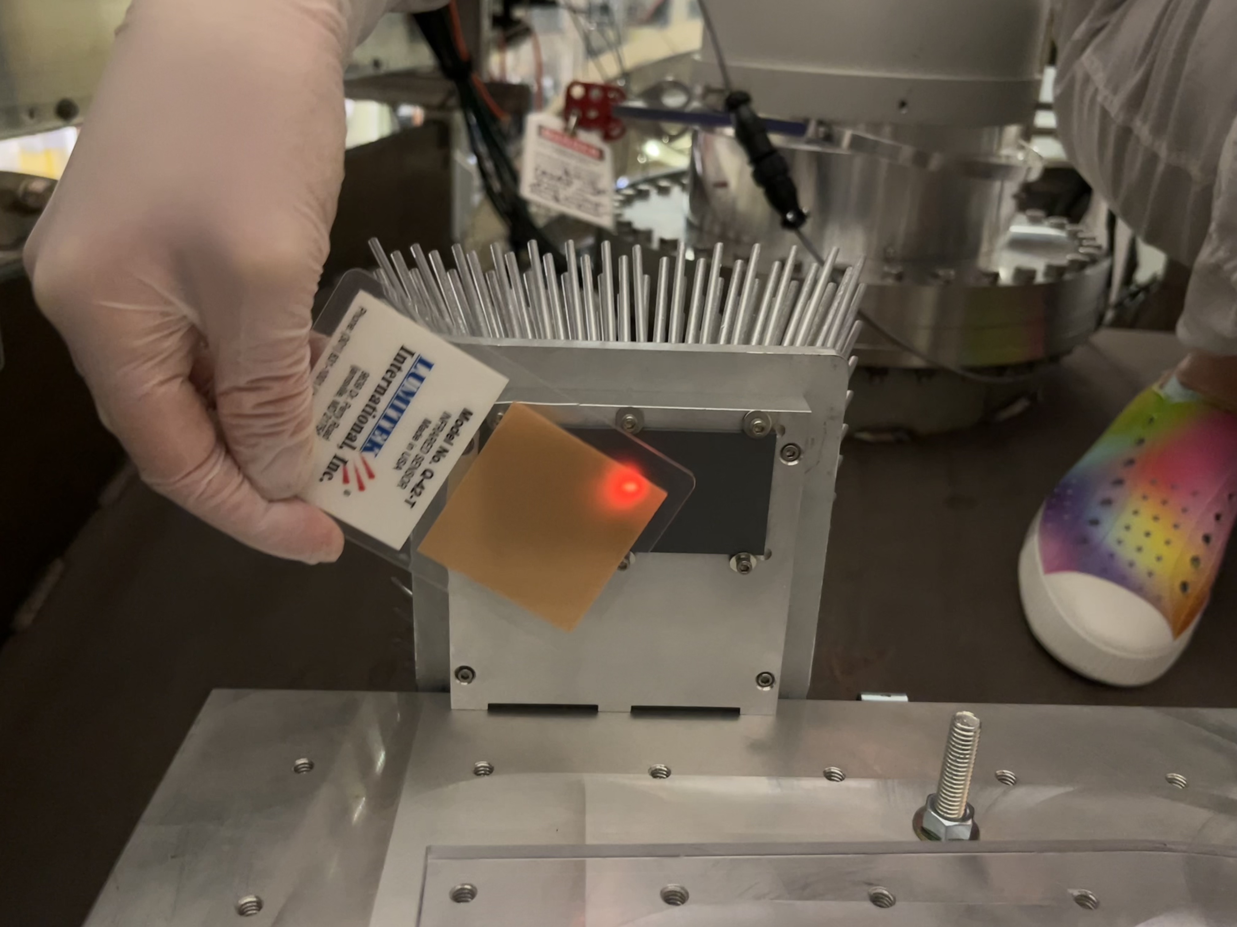
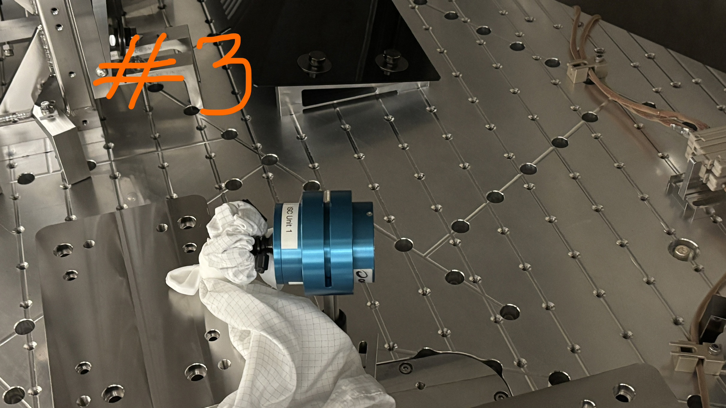
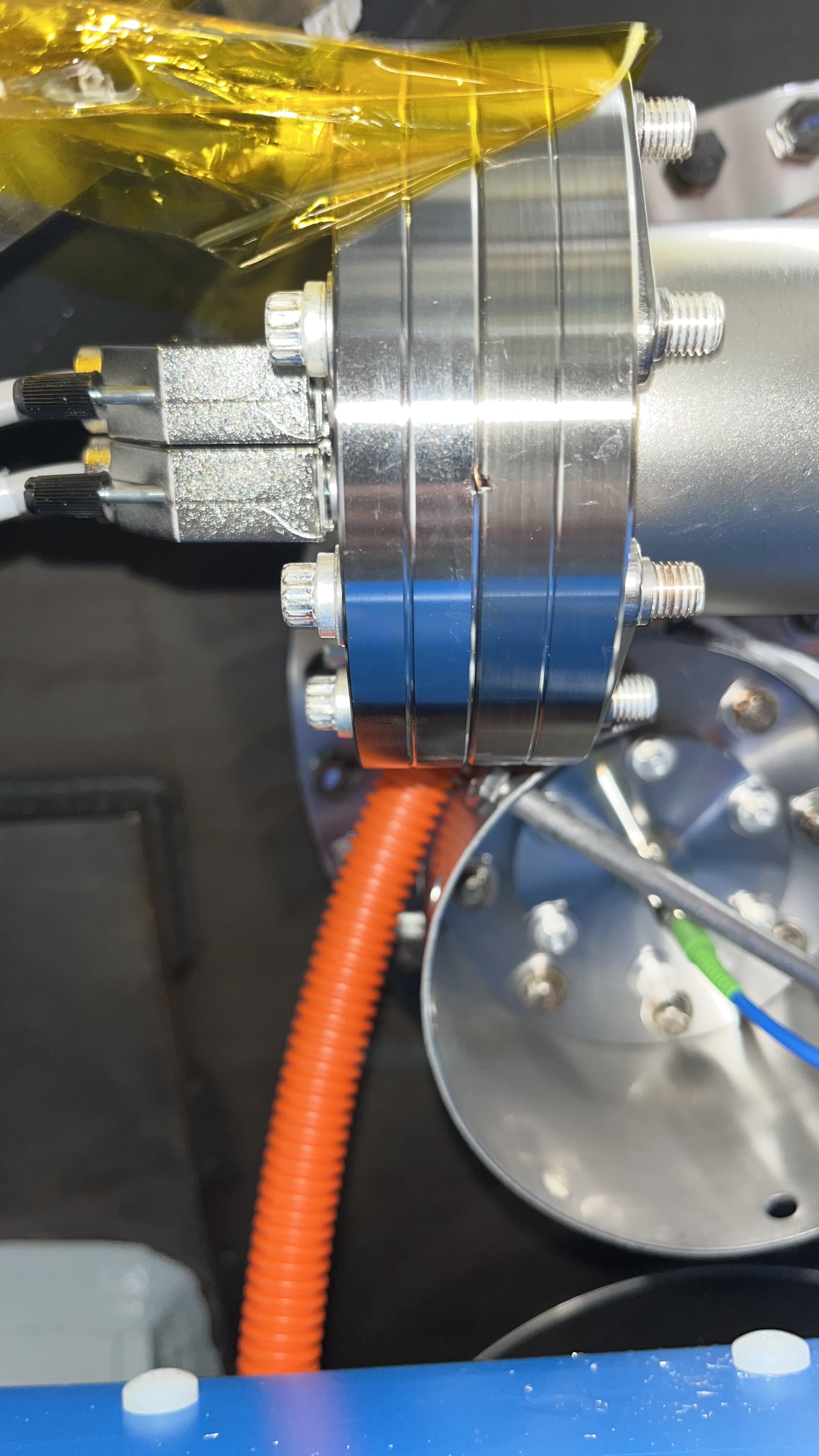
* Visually inspected the new batch of 10 flexures after c&b (see picture 2), and brought them to the H2-PSL (no issues found so far)
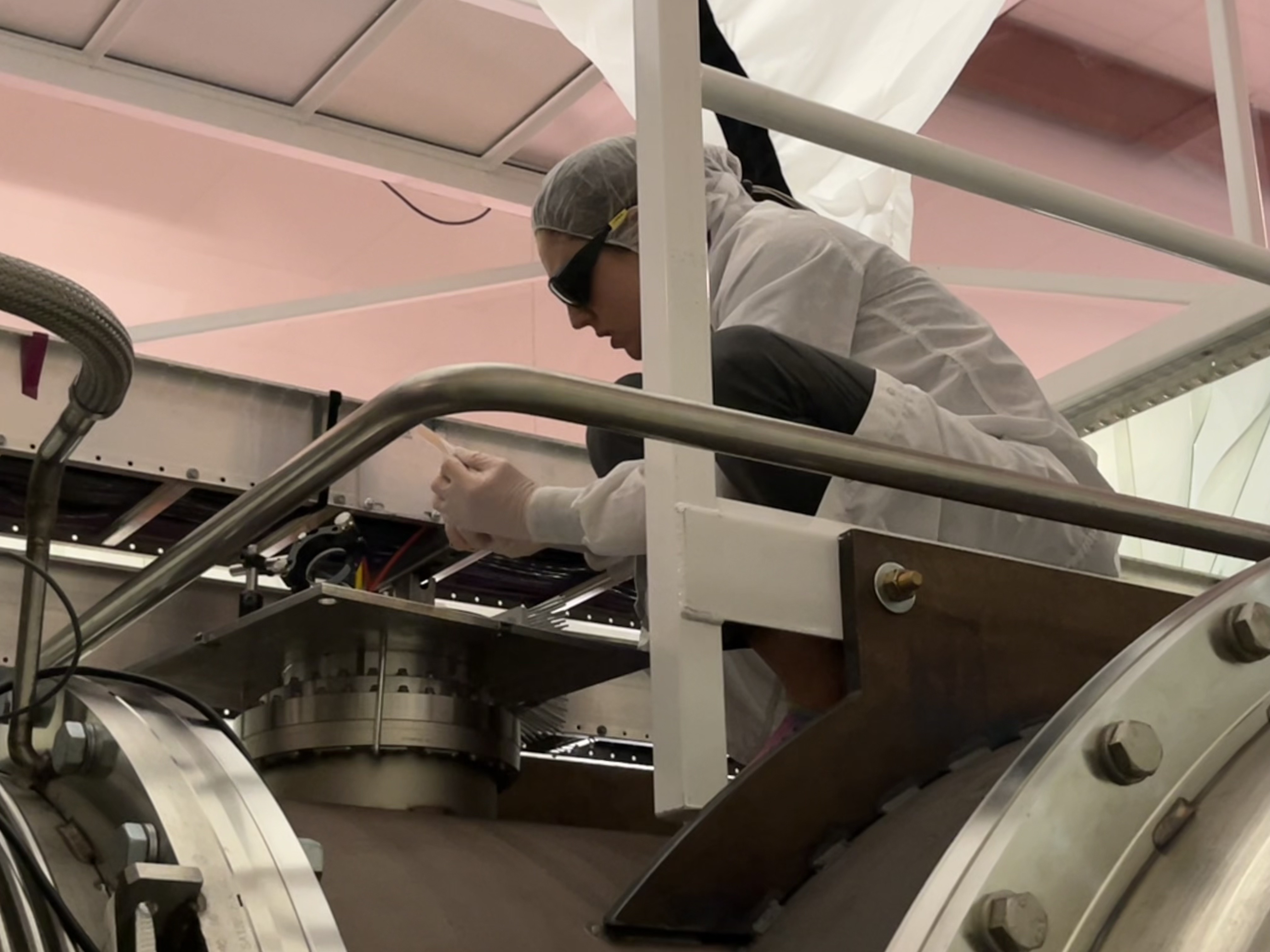
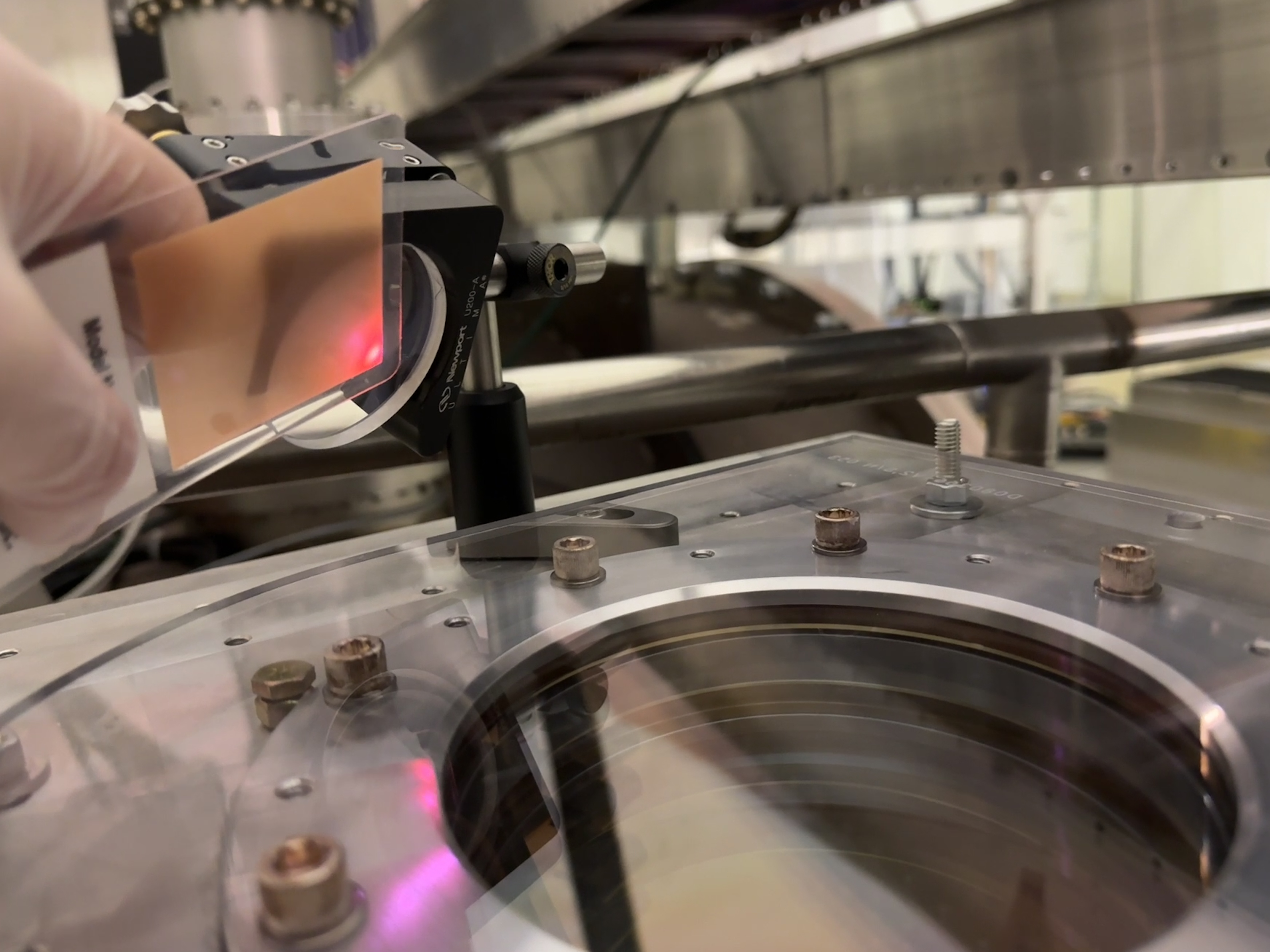
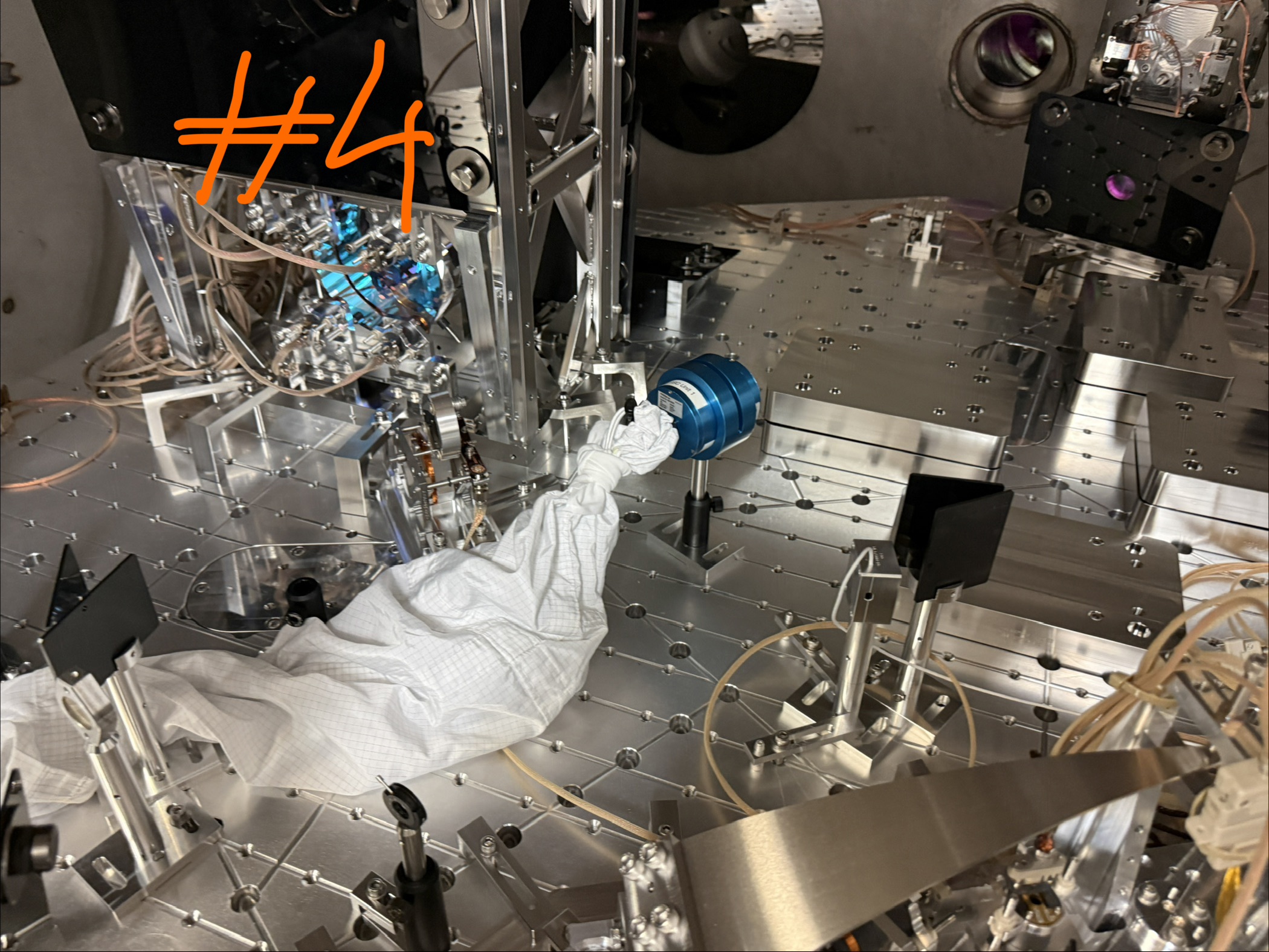
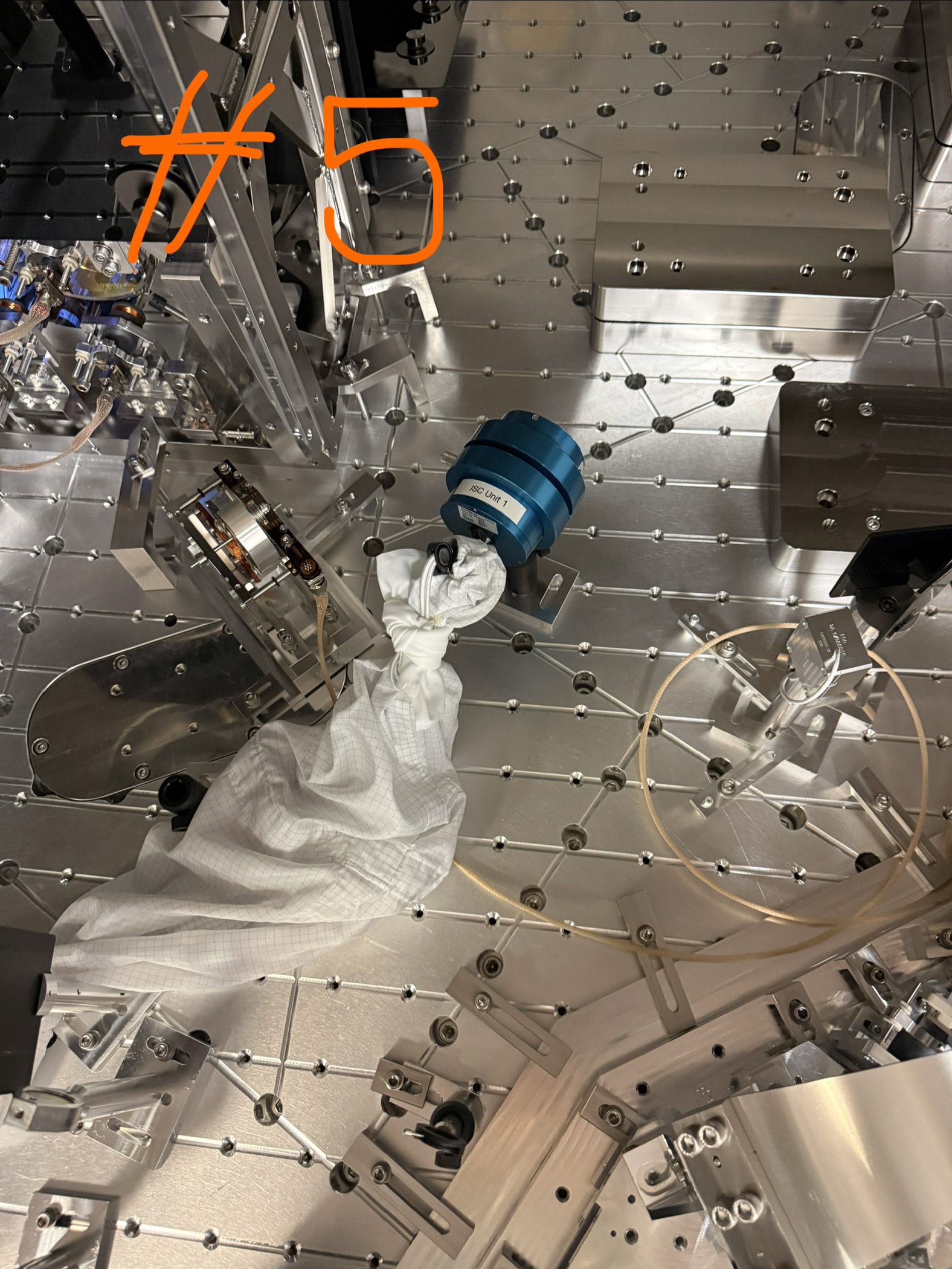
* Started setting up the Panasonic optical readout for CRS balancing. We will need some basic components from the optics lab to hold this readout.

Items borrowed from the EE shop :

x2 GWINSTEK power supply
x1 Hewlett P power supply
x1 multimeter with probes
x1 Techtonik oscilloscope 
x1 Bnc banana plug
x4 bnc to clips
x4 bnc cables
x1 db9 cable
x3 power cables
x3 breakout boards (x2 db9 and x1 db25)
x3 db9 gender changers

Images attached to this report
H1 CDS
jonathan.hanks@LIGO.ORG - posted 17:06, Monday 01 June 2026 (90428)
WP 13286 Migrating the fmcs IOC off of the mac mini failed

As per WP 13286 I tested the copy of the fmcs epics ioc that I had extracted from fmcs-epics-cds.  Unfortunately the IOC would crash each time I ran it.  There was not time to debug and see if it could be fixed today.  So the mac mini is still running the ioc.

H1 AOS
sheila.dwyer@LIGO.ORG - posted 17:03, Monday 01 June 2026 - last comment - 14:47, Tuesday 02 June 2026(90426)
HAM7 started placing irises

Sheila, Camilla, Disha

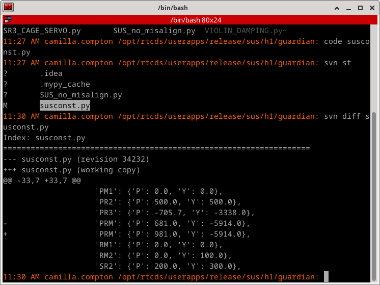
After Jim locked the ISI, Marc bypassed the high voltage interlock, and Camilla restored the psams, we reset the alignment sliders following 90483 which was in air.   The dither locking worked without any issue, and we saw that the beam was low on both the irises in the homodyne path on SQZT7.  Camilla adjusted the alignments of ZM4+ZM5 to center the beam on the irses, screenshot attached shows the alignment that she found.  

We placed an iris in front of ZM4 for this alignment, we were able to look from the +X side of the chamber to check the centering.  We also took photos of the IR/green co-alignment, it looks good coming right off the VIP, but looking right after ZM3 you can see that there is a small misalignment in yaw.  We will continue with placing irses tomorow.  


Images attached to this report
Comments related to this report
sheila.dwyer@LIGO.ORG - 14:47, Tuesday 02 June 2026 (90444)

This morning we reverted the -710 counts on H1:SYS-MOTION_C_PICO_J_MOTOR_3_X_POSITION (H:M2 yaw), undoing the change that we made in 89596.  This seems to have improved the co-alignment, I will attach a photo here to compare to the co-alingment photos from yesterday (90426)

We also lowered the PZT scan range to get the OPO seed dither locking to work well, as it was trying to lock at the top of the PZT range and not staying locked.  (line 654 of the OPO guardian).  

We attempted to go to the alignment in 89694 to check the alignment of FC1, but we saw that FC1 was not actuating.  This is probably why Camilla had to adjust the alignments of ZM4 + ZM5 yesterday.  90426.  The CDS team is working on the issue with FC1 alignment.  


H1 AOS
anamaria.effler@LIGO.ORG - posted 16:38, Monday 01 June 2026 (90425)
Quad cage baffles staged for ITMY

Betsy, Anamaria

With the helpful kits Mitchell had prepared, we assembled the cage baffle brackets and panels on a table by BSC1; this includes CP and HR cage baffles. We chose SN 3's for ITMY and SN 4's for ITMX for both panels and brackets. We also checked that we have the various tools we need chamber side. Still need to make one more set of brackets for ITMX CP baffle, but that can wait. We found and staged two ACB long lockers but only one wedge. 

LHO General
ryan.short@LIGO.ORG - posted 16:35, Monday 01 June 2026 (90424)
Ops Day Shift Summary

TITLE: 06/01 Day Shift: 1430-2330 UTC (0730-1630 PST), all times posted in UTC
STATE of H1: Planned Engineering
INCOMING OPERATOR: None
SHIFT SUMMARY: Very busy day with lots of visitors on site! Essentially everything was recovered following the weekend power outage, doors on HAM7 were removed and SQZ work in the chamber started after the ISI was locked, QOSEM work continued on the BBSS, the ISI was balanced on the test stand, prep began for the ITM cage baffle installation, GV7 was cycled and left closed for venting of the X-manifold, more beam alignment went on in HAMs 2 and 3, turbopumps at EY and MY were tested, FARO surveying began in HAM3, CRS building continued, and SPI work in the optics lab is ongoing. The EDC is still showing several disconnected channels, some of which relate to EY dust monitors.
LOG:

Start Time System Name Location Lazer_Haz Task Time End
19:29 SAF Laser HAZARD LVEA YES LVEA is Laser HAZARD 17:21
14:36 FAC Kim LVEA - Technical cleaning 17:01
14:43 FAC Randy LVEA - Prep for HAM7 doors 15:12
15:01 VAC Jordan LVEA - Checking pumps 15:10
15:37 SPI Jeff Opt Lab Local Turning on laser 17:00
15:38 IAS Ryan C LVEA - Checking on FARO 15:47
15:46 ISC Keita LVEA - Opening light pipe 15:48
15:46 VAC Jordan MY, EY - Turbopump checks 16:40
16:04 PSL Jason LVEA - Powering on PSL CB2 16:22
16:19 VAC Travis Lvea - HAM7 door prep 16:25
16:28 SAF Ibrahim LVEA - Transition to SAFE 17:21
16:54 SUS Oli, Tom LVEA - BBSS QOSEM 18:19
17:21 SUS Ibrahim LVEA - BBSS work 18:19
17:22 FAC Randy LVEA - HAM7 door removal 19:22
17:22 VAC Travis, Jordan LVEA - HAM7 door removal 18:40
17:22 FAC Kim EX, EY - Technical cleaning 18:19
17:24 CDS Erik EY, EX - Power outage recovery 18:27
17:29 VAC Gerardo LVEA - HAM7 door removal 18:41
17:33 SLiC Mitch, Anamaria LVEA - Baffle install planning 17:46
17:38 SPI Corey Opt Lab - Optic cleaning 19:46
18:15 IAS Jason, Ryan C LVEA - FARO surveying HAM3 20:33
19:04 SAF Sheila LVEA YES Transition to Laser HAZARD 19:26
19:09 TCS Camilla MER - Turning on TCS chillers 19:25
19:26 SAF Laser HAZARD LVEA YES LVEA is Laser HAZARD Ongoing
19:27 SEI Shoshana, Arnaud H2 PSL - CRS builds 19:53
19:34 SEI Jim LVEA - Locking HAM7 ISI 19:54
19:55 SEI Jim EX, EY - Bringing up HEPI 20:33
20:13 SPI Jeff, Sina Opt Lab Local SPI alignment 22:04
20:24 VAC Jordan, Jake, Owen EY, MY - Shutting down turbopumps 21:20
20:33 ISC Marc, Keita CER - PZT power supply 20:37
20:50 SLiC Betsy, Anamaria LVEA - Staging for baffle install (Anamaria out @ 23:04) Ongoing
20:59 SEI Jim, Ibrahim LVEA - BBSS ISI balancing Ongoing
21:08 VAC Travis, Gerardo LVEA - X-man vent and open GV2 (Gerardo out @ 23:03) Ongoing
21:24 VAC Jordan, Jake, Owen LVEA - X-man vent and open GV2 22:18
21:28 SEI Marc, Patrick MER - HEPI electronics 21:58
21:30 SQZ Sheila, Camilla LVEA Y HAM7 SQZ beam hunting (Camilla out @ 22:58) Ongoing
21:38 IAS Jason, Ryan C LVEA - FARO surveying HAM3 Ongoing
21:58 ISC Keita, Rahul, Disha LVEA Y HAM2/3 beam alignment Ongoing
22:04 SEI Arnaud, Shoshana, Alex H2 PSL - CRS builds (Alex out @ 23:11) Ongoing
22:32 VAC Jordan, Jake, Owen LVEA - Venting X-manifold Ongoing
22:35 SPI Jeff, Sina Opt Lab Local SPI alignment (Jeff out @ 23:05) Ongoing
23:18 AOS Mitchell LVEA - Delivering garb Ongoing
H1 CDS
erik.vonreis@LIGO.ORG - posted 14:55, Monday 01 June 2026 - last comment - 17:00, Monday 01 June 2026(90422)
Model restart and DAQ restart

[Jonathon, Ollie, Erik v., Tom]

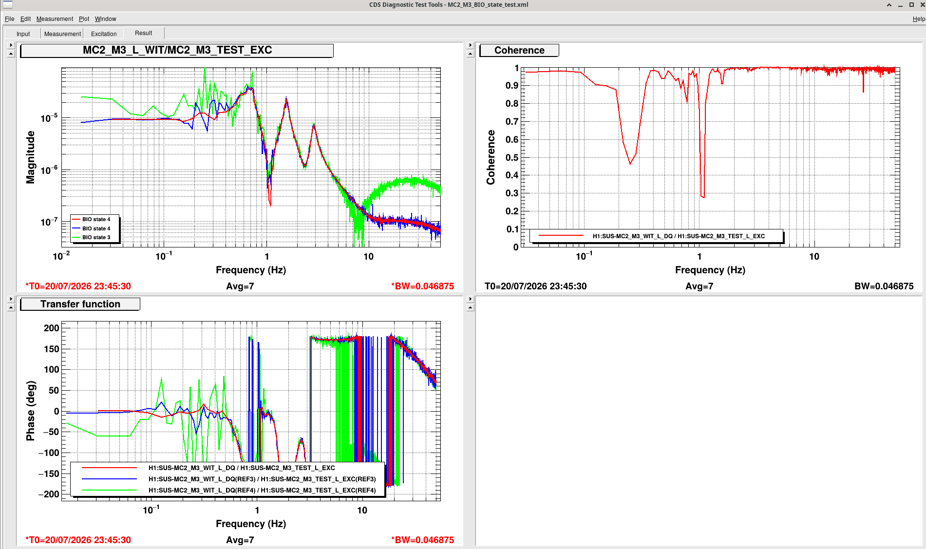
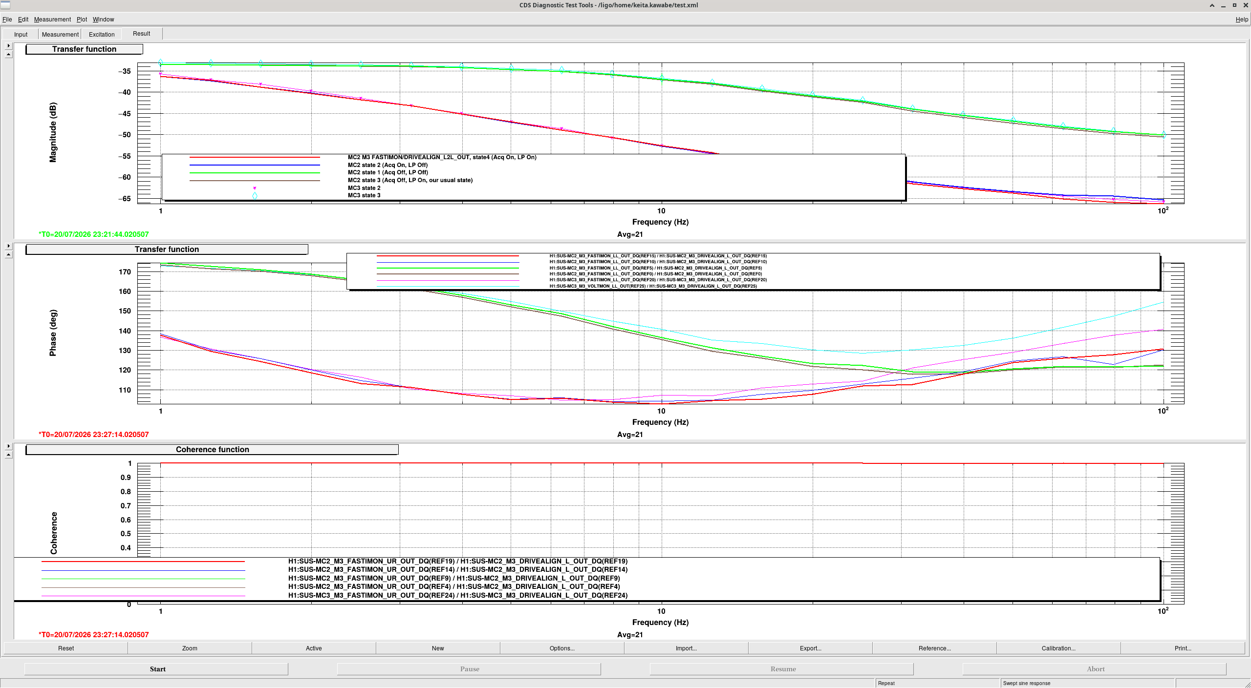
h1susbs front end model was shut down and h1suslo12 was rebuilt and restarted, moving control of mc2 form h1susbs to h1suslo12.

This required DAQ and EDCU restarts.  The DAQ restart ran into problems because some channes were renamed (temporarily, hopefully) from BS to BBSS that were part of the GDS broadcast.  These channels have been renamed in the broadcaster lists for h1daqgds0 and g1daqgds1.

Comments related to this report
jonathan.hanks@LIGO.ORG - 17:00, Monday 01 June 2026 (90427)

The following channels where removed from the broadcast list:

H1:SUS-BS_M1_DAMP_L_IN1_DQ
H1:SUS-BS_M1_DAMP_P_IN1_DQ
H1:SUS-BS_M1_DAMP_R_IN1_DQ
H1:SUS-BS_M1_DAMP_T_IN1_DQ
H1:SUS-BS_M1_DAMP_V_IN1_DQ
H1:SUS-BS_M1_DAMP_Y_IN1_DQ
H1:SUS-BS_M2_WIT_L_DQ
H1:SUS-BS_M2_WIT_P_DQ
H1:SUS-BS_M2_WIT_Y_DQ
H1:SUS-BS_M3_OPLEV_PIT_OUT_DQ
H1:SUS-BS_M3_OPLEV_SUM_OUT_DQ
H1:SUS-BS_M3_OPLEV_YAW_OUT_DQ

They were replaced by BBSS variants:

H1:SUS-BBSS_M1_DAMP_L_IN1_DQ
H1:SUS-BBSS_M1_DAMP_P_IN1_DQ
H1:SUS-BBSS_M1_DAMP_R_IN1_DQ
H1:SUS-BBSS_M1_DAMP_T_IN1_DQ
H1:SUS-BBSS_M1_DAMP_V_IN1_DQ
H1:SUS-BBSS_M1_DAMP_Y_IN1_DQ
H1:SUS-BBSS_M2_WIT_L_DQ
H1:SUS-BBSS_M2_WIT_P_DQ
H1:SUS-BBSS_M2_WIT_Y_DQ
H1:SUS-BBSS_M3_OPLEV_PIT_OUT_DQ
H1:SUS-BBSS_M3_OPLEV_SUM_OUT_DQ
H1:SUS-BBSS_M3_OPLEV_YAW_OUT_DQ

We are told in a future update the original names will be restored.

H1 IOO (IOO, ISC)
keita.kawabe@LIGO.ORG - posted 14:54, Monday 01 June 2026 (90421)
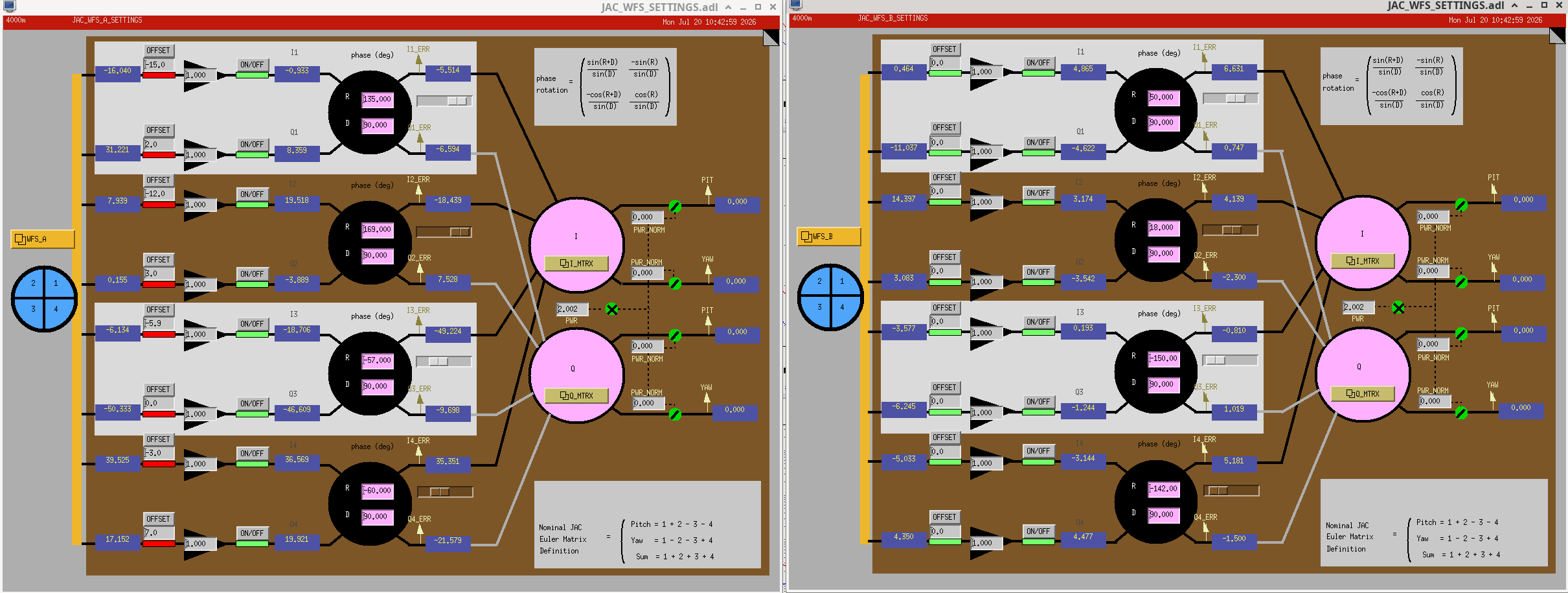
JAC recovery from power outage (Ryan, Patrick, Marc, Rahul, Jenne, Keita)

JAC PZT HV was off -> Mark reset the interlock.

JAC heater chassis was off -> I switched it on at the rack.

JAC error signal was not crossing zero -> I updated the dark offset H1:JAC-REFL_A_RF43_I_OFFSET to a new number 2.4.

Beckhoff was reporting "invalid value" error for JAC PZT whitening -> Patrick did something to clear that.

Rahul restored slider numbers for JM1/3, IMC1/2/3, IM1/2/3/4 and PRM to Friday evening numbers as he reported in alog 90419.

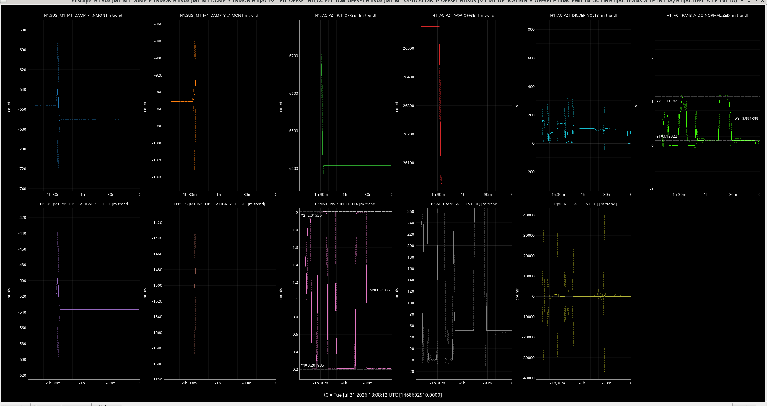
JAC guardian didn't want to lock because H1:JAC-TRANS_A_DC_NORMALIZED kept getting below the threshold of 0.5. -> I temporarily changed it to 0.1.

JAC PZT voltage was drifting quickly for 30 minutes or so and JAC kept unlocking (probably because JAC was heating up) -> waited for a while.

JAC still didn't want to keep lock for a long time. -> I put it to DOWN state, followed the resonance manually using the PZT voltage for a minute or so, changed the state to LOCKED and the guardian liked that.

Jenne refined the JAC alignment using PZT and JM1. H1:JAC-TRANS_A_LF_OUT_DQ momentarily went up to 620 and the best number in the past month before today was like 580. It's trending down in the past two hours, now it's ~580 and that's still a very good number.

Temperature drift is still going on, the symptom is that the PZT voltage drifts down to -10 Volts and at that point JAC unlocks, but the guardian relocks to higher voltage fringe position right away, and the drift is slow enough it's bearable. Last lock lasted for an hour.

Now we can set H1:JAC-TRANS_A_DC_NORMALIZED back to 0.5 if we want to.

H1 ISC
jenne.driggers@LIGO.ORG - posted 14:24, Monday 01 June 2026 (90420)
Quick notebook script to calculate pit/yaw values when beam is flashing

Aligning beams onto QPDs while the IMC is flashing (eg, during a vent) is very challenging.  We want to know what the pit and yaw values are, but can only trust the values at a moment when there is a flash.

The jupyter notebook that has just been placed into git can (with lots of patient help from Jamie Rollins) read data that has been exported from an ndscope (so, can be data that is not DQ'd), and then will calculate the pitch and yaw values at the time of the largest flash in that time window.  

This is a direct link to the notebook right now for a snapshot of this first iteration, and you can see the plots at the very end and a printout of the pit/yaw values of all of the QPDs that I have collected data for.

Hopefully this will help make things a bit quicker as we work to center on our various ASC PDs and close out this vent.

H1 SUS (SUS)
rahul.kumar@LIGO.ORG - posted 14:20, Monday 01 June 2026 (90419)
SUS alignment sliders for HAM1_2_3 restored to Friday evening (6.30pm) values

I have restored the SUS alignment slider values (P/Y) for all the suspensions in HAM1, 2 and 3 chambers (i.e JM1, JM3, MC1, MC2,, IM1, IM2, IM3, IM4) which had changed after the Saturday site power outage. I trended the pitch and yaw slider values for all of the suspensions in these three chambers and restored the ones which I found have changed. I selected Friday evening (29 May 2026, 6.30 PM when Keita et al were done with moving the suspensions).

Images attached to this report
H1 SQZ
camilla.compton@LIGO.ORG - posted 14:05, Monday 01 June 2026 (90418)
HAM7 HiVoltage Bypass On

Marc and I turned on the HAM7 Hi Voltage Bypass in the Mech Rm Mezzanine. We first turned the PSAMS down to zero, they hadn't been zero'ed before Hi-voltage was turned off. WP13282

H1 IOO (INS, IOO, ISC)
keita.kawabe@LIGO.ORG - posted 12:34, Monday 01 June 2026 - last comment - 12:34, Monday 01 June 2026(90404)
IMC, IM2/3/4 and PRM are aligned, cannot center ASC REFL sensors (JennieW, Rahul, Keita)

Belated alog from Friday.

Summary:

After realigning IMC and IM2 on Thursday, we continued aligning IM3 to put the beam in front of the PRM to the nominal position, IM4 to set the beam position in front of PR2, and PRM so the beam retroreflects. IM1 was left untouched, so the only change in IM1-IM2 line is from the change in the IMC alignment.

Clipping on IM4 baffle (HA12) disappeared completely. Beam position on IFI output baffle looked OK. Beam position on IFI input baffle didn't change (as expected) and still looked OK. There are some mystery 

We saw flashes on ASC REFL sensors but they were weak. We tried to center them using RMs but RM2 seems to rail in YAW.

  Before P, Y [urad] After P, Y difference P,Y
RM1 -196, 281.8 -242, -19.3 -46, -301.1
RM2 910, 490 912.1, -2125.15 (railing) +2.1, -2615.15

What to do:

Scan PRM to make sure that we're NOT looking at some kind of ghost beam on ASC REFL sensors.

Assuming that we're looking at the real beam on REFL sensors, we can do either (or some of) these:

Images attached to this report
Non-image files attached to this report
Comments related to this report
keita.kawabe@LIGO.ORG - 01:09, Monday 01 June 2026 (90405)

See screenshot for before/after slider values for RM, IM and other optics.

Images attached to this comment
keita.kawabe@LIGO.ORG - 11:36, Monday 01 June 2026 (90412)

Baffle pictures. Whenever appropriate, there are two pictures (one to access PIT and the other to access YAW) to avoid the parallax problem as the thickness of the baffles cannot be ignored.

IFO REFL looks good on the IFO REFL baffle (HA13) in front of the HAM2-HAM1 septum window (IFO_REFL_HA13.jpg).

IM4 baffle (HA12) is good in PIT (IM4_HA12_PIT_good.jpg), not great in YAW but is OK (IM4_HA12_YAW_OFF.jpg). Next time I'll take a picture through IM4 to show you it's quite acceptable than it looks from these pictures.

IR picture of the IM4 baffle (HA12) shot from IM3 side shows a ghost beam it catches when there's a flash (IM4_HA12_ghostbeam.jpg). Circled in red is the ghost beam (in this case it was 10 mode flash). Circled in green are things that are always visible (IM4_HA12_noflash.jpg) and aren't the ghost beam.

IFI input beam position is great in PIT, not great in YAW (IFI_INPUT_PIT_GREAT_YAW_OFF.jpgIFI_INPUT_PIT_GREAT.jpg).

However, I still see some kind of clipping of bacdkward-going beam once in a while. See the IR photo shot from IM3 direction IFI_INPUT_clipping.jpg. You're looking at the baffle aperture through calcite wedge from the direction of IM1. Compare with IFI_INPUT_noflash.jpg where there was no flashing.

Not every flash shows this clipping-like thing, it seems to happen less frequently than the flashing. 

To make things more confusing, there's a reflection of something shiny in IFI and the edge of that shiny thing is almost on top of the edge of the IFI input baffle aperture so it's hard to say what's going on.  Nothing like this was visible on the input side facing IM2.

We temporarily moved IM1 to move the beam spot on IM2 more centered (IFI_INPUT_IM1movedtocenter.jpg) and I can see something closer to the center (probably scattering from the CWP?) but no clipping. So probably it's a good thing to move IM1 counter-clockwise as I indicated in the alog above. We cannot do it too much as we rail RM2 in the opposite direction, but we can probably move the beam by a mm or so on IM2.

Images attached to this comment
H1 TCS
camilla.compton@LIGO.ORG - posted 12:22, Monday 01 June 2026 (90416)
TCS CO2 Chillers turned back on after power outage

Both CO2X and CO2Y Chillers turned back on with no issue. Interestingly as the laser is off they are currently heating the water. 

H1 CDS
david.barker@LIGO.ORG - posted 11:41, Monday 01 June 2026 (90414)
CDS Recovery Status

All CDS systems have been recovered with the exception of EY dust monitor. The EY Comtrol serial-to-ethernet is not working, Erik is replacing its power supply.

Erik started the HWS code. At EX he powered up the h1cdsrfm expansion chassis and power cycled the BRS_EX. At EY he powered the expansion chassis.

We started h1cdsrfm which has cleared all the long-range-dolphin IPC errors. EY WAP just needed powering up via the Pulizzi.

Patrick started the code on the Beckhoff systems for CHILLER_CS, CHILLER_EX, BRS_EX, BRS_EY, NCALX and  MAINS_EX.

EDC is currently down to 16 disconnected channels, all EY_DUST.

H1 SPI (CDS, Laser Safety)
jeffrey.kissel@LIGO.ORG - posted 11:30, Monday 01 June 2026 (90413)
2026-06-01 SPI Pathfinder Power Outage Recovery: No issues
J. Kissel"
As is all over the aLOG this morning, LHO had back-to-back site-wide power-outages this past Saturday 2025-05-30 -- LHO:90395. Here's the quick, pain-free record of recovering the SPI pathfinder's function to the levels we left it on Friday 2026-05-29 (LHO:90382). 

LASER
State of laser as I found it (entering the lab with laser safety googles ON):
    - Yellow chain and signage across the entry warning of "laser running unattended" still blocking entry. 
    - Magnetic lock of "outer" curtain released, manually hook-locked "inner" curtain still closed.
    - Laser hazard sign OFF
    - Laser STOP Button still "OUT" (in the ON position)
    - Laser Hazard sign still keyed "ON"
    - NPRO shuttered, still keyed ON, but not powered.

In short -- everything worked as expected in the event of a power outage if it happened while a laser system was running unattended.

    RECOVERY (all with laser safety glasses ON; obviously but just saying it "out loud"):
    - Unchained and stored "unattended laser" sign.
    - Pushed in ("OFF") laser stop button.
    - Keyed OFF laser hazard sign.
    - Pulled out ("ON") laser stop button to allow for re-energizing of interlock.
    - Keyed ON laser hazard sign.
    - Closed magnetic "outer" curtain and swiped in, laser hazard sign lit up as expected.
    - Confirmed NPRO laser output is shuttered. 
    - Looked at NPRO controller, red light ON under the OFF button (as expected because it was already/still keyed ON).
    - Plugged in and turned on PD100D interface for on-board S304C power monitor PD (installed within the laser conditioning/fiber collimating bread-board), confirming 1064 [nm] wavelength readout settings.
    - Waited ~2 minutes for the diodes' controllers to settle, then hit the green ON button
    - No issues with diode temp transients, laser worked just fine.
    - Unshuttered laser, and on-board S304C power monitor PD happily confirmed the expect ~198 [mW].

ELECTRONICS
State of electronics as I found it: 
    - Electronics +/-18 V and +/-24.0 V power supplies were ON, with their outputs producing voltage at their nominal settings.
    - Laser prep chassis and PD TIA chassis all showed happy green lights.
    - Keysight 33600A RF source had reset, with outputs off and all the wrong settings.

    RECOVERY (all with laser safety glasses ON; obviously but just saying it "out loud"):
    - Ran through T2600039 to restore all frequency settings
    - Exported March 2026 notes to LHO:90409 and restored CH1 (REF) and CH2 (MEAS) amplitude settings to -1.7 and -1.4 [dBm], respectively
    - Turned CH1 and CH2 output ON.
    
    Laser Prep Chassis SM05PD01A monitor PD ADC voltage: 7.83 [V].
    Laser Prep Chassis RF monitors M2 (REF) and M3 (MEAS) ADC voltage: ~750 and ~750 [mV]
    FBR_PWRIN_REF On-board power monitor PD ADC voltage: 4.68 [V].
    In short :: All these monitor ADC voltages are at normal values.

SPI IFOs
    No actions required after turning on LASER and ELECTRONICS.
    REF IFO Efficiency -- 4.96 V / (2 * 2.69V) = 0.922
    MEAS IFO Efficiency -- 3.00 V / (2*3.95 V) = 0.38

Recovered! 
Hopping back into The Mystery Machine...
H1 TCS
camilla.compton@LIGO.ORG - posted 10:31, Monday 01 June 2026 - last comment - 00:48, Thursday 02 July 2026(90411)
Started to assemble D1700340-type02 for CHETA VPs

Gerardo, Jordan, Camilla. 

On Thursday we assembled VAC sealing part of the CHETA VPs, D1700340-type02. The thinnest part of the optics are at 12o'clock if the VP is oriented with the P/N of D1700338 writing also ~12o'clock. 

D1700338-v2-001 with D1700339-v2-001 and D1700338-v2-003 with D1700339-v2-003. Both have optics D1100439-type02, which are DAR coated for 1064nm and 10.6um. 

Next steps is VAC testing, then first contact the window surfaces and add secondary window.


Images attached to this report
Comments related to this report
gerardo.moreno@LIGO.ORG - 00:48, Thursday 02 July 2026 (90867)VE

(Jordan, Jake, Owen, Gerardo)

Today we pressure and leak tested the viewports for CHETA.  Both of the assemblies passed their tests, no issues to report.
Both viewport assemblies were pressure tested by applying vacuum pressure on the vacuum side of the assembly <1X10-03 Torr with a leak detector, and positive pressure on the air side, 15.5 psig using nitrogen gas.  The new test cap worked great.
Next step is to finish the assemblies and install them.

Since the assemblies do not have an assembly number I'll list them as 003 and 001 due to their components SNs.  The background reported by the LD at startup was at <1X10⁻¹⁰ Torr*L/Sec.  These are LIGO viewports and they have a viton O-ring, thus He will permeate thru the O-ring, also the testing jig has two more O-rings.  The signal did not shot up to the recorded number, it slowly got there.

  • Assembly 003, after spraying it with He for about 5 seconds on two places the LD reported a leak rate of 3.3X10-09 Torr*L/Sec.
  • Assembly 001, same process as above, the LD reported a leak rate of 6.3X10-09 Torr*L/Sec.


Images attached to this comment
LHO General
ryan.short@LIGO.ORG - posted 07:39, Monday 01 June 2026 - last comment - 08:24, Monday 01 June 2026(90407)
Ops Day Shift Start

TITLE: 06/01 Day Shift: 1430-2330 UTC (0730-1630 PST), all times posted in UTC
STATE of H1: Planned Engineering
OUTGOING OPERATOR: None
CURRENT ENVIRONMENT:
    SEI_ENV state: MAINTENANCE
    Wind: 7mph Gusts, 5mph 3min avg
    Primary useism: 0.02 μm/s
    Secondary useism: 0.16 μm/s 
QUICK SUMMARY: Will continue recovery of various sytems following power outages over the weekend and will work on discovering what still needs attention.

Comments related to this report
ryan.short@LIGO.ORG - 08:24, Monday 01 June 2026 (90408)

Current status:

  • Cannot remote login to PSL computer to restart the laser
    • I expect I won't be able to power it on anyway as the benchtop power supply in the PSL racks powering CB2 probably needs to be turned back on manually
    • Site laser interlock is tripped too; can't reset since PSL Beckoff is down
  • HEPI_ETM{X,Y} and CDS_CA_COPY Guardian nodes were in error, reloading fixed
    • Guardian machine does not seem to have gone down as nodes all look okay
  • All suspesnions recovered (except BS and ITMs, did not touch these)
  • All HEPI pump stations are down, cannot untrip HEPI
    • Not untripping ISIs while HEPIs are down
  • ISI HAM8 recovered, ISI HAM7 recovered but then quickly tripped again (chamber is vented, makes some sense)
  • Cannot seem to trend any data via ndscope before the outage on Saturday
  • End BRSs are down (if Beckhoff is still down, this makes sense)
H1 CDS
david.barker@LIGO.ORG - posted 09:36, Sunday 31 May 2026 - last comment - 10:03, Monday 01 June 2026(90403)
State of CDS following recovery from second power outage

Thankfully no more power outages following the second (14:27) outage Sat 30may2026. Here are the systems we left offline which will be restarted tomorrow, Mon 01jun2026.

PSL Diode Room Beckhoff Controls

Long range dolphin end station Adnaco expansion chassis (h1cdsrfm)

NCAL EX

BRS EX, EY

HWS EX, EY

MAINSMON EX

CHILLERMON EX, EY


Comments related to this report
david.barker@LIGO.ORG - 07:36, Monday 01 June 2026 (90406)

Here are all the MSR UPS Emails we received on Saturday. The UPS clock appears to be incorrect and about 14mins fast. No GC UPS emails were received on Saturday.

Sat Morning Outage 09:39

Date: 05/30/2026
Time: 10:12:59
Code: 0x0002
Critical - System: Warmstart. (2 copies received)

Date: 05/30/2026
Time: 10:13:06
Code: 0x0101
Informational - UPS: Restored the local network management interface-to-UPS communication.

Sat Afternoon Outage 14:27

Date: 05/30/2026
Time: 14:45:38
Code: 0x020F
Critical - UPS: An input voltage or frequency problem prevents switching to bypass mode. (4 copies received)

Date: 05/30/2026
Time: 14:45:40
Code: 0x0109
Warning - UPS: On battery power in response to an input power problem. (2 copies received)

Date: 05/30/2026
Time: 14:45:45
Code: 0x010A
Informational - UPS: No longer on battery power. (2 copies received)

Date: 05/30/2026
Time: 14:45:57
Code: 0x0210
Informational - UPS: An input voltage or frequency problem no longer prevents switching to bypass mode. (2 copies received)


erik.vonreis@LIGO.ORG - 10:03, Monday 01 June 2026 (90410)

h1hwsex and h1hwsey are running in a tmux session.  To get to the process, ssh as controls to the server and run "tmux a".

H1 AOS
joshua.freed@LIGO.ORG - posted 15:30, Monday 16 March 2026 - last comment - 09:12, Monday 01 June 2026(89523)
SPI, Prep Chassis RF Input Chain to Monitor output Chassis

J. Freed

For the build of SPI, I measured the expected power output from a dual source Keysight 33600A through SPI's 2W amp D2500004. These measurements were taken with a E4418A EPM power meter using the HP 8484A 30dB attenuator attachment. After analyzing the data it is hard to say that the power meter power readings were accurate but the power the AOMs are receiving should be below the damage threshold of 33dBm.

I measured the power at 2 points in the chain from Keysight -> 2W  -> SPI prep, for both channels. (SPI_Build_RF_Diagram.png) The first point is just before the 2W amp, and the second point is just before the SPI prep for both channels. Then I compared that with what the output monitor voltage was showing on SPI prep for both channels.


Power_Before_2W_Amp.png Is the data collected from power measurements just before the 2W amplifier. The limit of 22dBm is the limit of the keysight. From this it can be seen that there is not a 1-1 measurement between what the keysight says it is outputting and what the HP 8484A sensor is measuring. This difference is also changing based on the input power itself. With lower power overestimating what the keysight says its outputting, and higher power underestimating what the keysight says its outputting. This is a problem with the probe as switching out the probe to an E-series gives a relatively consistent error of -0.2dB between what the keysight says its outputting and what is being measured. Unfortunately the HP 8484A sensor is the only probe that can measure up to the 32-32.5dBm needed for SPI. Interpolating the results of the HP 8484A sensor up to 32 dBm gives approximately a 0.4dB underestimation of the power.


Then I took a measurement of the power after the 2W amp at the end of the cable that would plug into SPI prep. Namely I adjusted the power from Keysight, such that the output measured on the probe was 32dBm which is what SPI prep is expecting accounting for any possible underestimation of the power. Note that power past the 2W amp decreases over time (by about 0.5dB total) as the device warms up so I had to wait a couple of hours after start-up to take this measurement. The results were:

AMP 1 (Which goes into the ref path) measured 32dBm when the keysight displayed: -1.7dBm

AMP 2 (Which goes into the Meas path) measured 32dBm when the keysight displayed: -0.3dBm

Be aware that that 32dBm has an error of +/- 0.5dB due to the factors listed above. 


Then using the fact above, I found that the whole AMP 1 chain has a gain of 33.7 dBm from what the keysight displays. And AMP 2 chain has a total gain of 32.3dBm from what the keysight displays. Using this fact I could find the voltage associated with each of the monitor channels of SPI prep.

Monitor_read_AMP1_REF.png and Monitor_read_AMP2_MEAS.png show the monitor reading voltage vs the approximate input RF power into SPI prep. for both channels. Interpolating the results gives a calibration equation between RF power and monitor voltage of: 

AMP 1 (REF):  [V] = -0.0249*[dBm] + 1.5480

AMP 2 (MEAS):  [V] = -0.0246*[dBm] + 1.5387

With both channels reaching 32dBm around 0.75V on the monitor channel this gives an easy target for controling the power.


Images attached to this report
Comments related to this report
jeffrey.kissel@LIGO.ORG - 09:12, Monday 01 June 2026 (90409)SPI
J. Kissel
Easy look up table after setting up Keysight 33600A per T2600039, and setting the amplitudes as we have had for most of the build ::

CH1 = AMP 1 = REF = M2 MON
    f = 79.995904 MHz (79,995,904 Hz)
    amp = -1.7 dBm
    M2 MON = 740 mV

CH2 = AMP 2 = MEAS = M3 MON
    f = 80.000000 MHz (80,000,000 Hz)
    amp = -1.4 dBm
    M3 MON = 755 mV

Remember to turn the output ON for each channel.
Displaying reports 461-480 of 88291.Go to page Start 20 21 22 23 24 25 26 27 28 End