V. Xu, R. Short, J. Oberling
Short short version: The PSL NPRO swap is done and IFO recovery has begun. I'll get a more detailed alog in tomorrow, right now I'm exhausted.
After the very successful PSL work this week, we're electing to not offload the temp changes for the ALS or SQZ lasers to their physical knobs tonight. This means that they all need Crystal Freqs of something near 1.6 GHz (1600 in the channel H1:ALS-X_LASER_HEAD_CRYSTALFREQUENCY). The new-ish ALS state CHECK_CRYSTAL_FREQ is written assuming that all the lasers have the changes offloaded to their knobs, so that the value in that channel is close to zero. After we went through SDF revert, we lost those values (and the search values, which Daniel has updated in SDF for the weekend), so we we lost the PLL lock of the aux lasers. The CHECK_CRYSTAL_FREQ state was 'fighting' us, by putting in candidate values closer to zero. I've updated its candidate values to be closer to 1600. Once we offload their temps to the knobs on their front panels (early next week), then we'll want to undo this change.
Current crystal frequencies: ALSX +1595 MHz, ALSY +1518 MHz, and SQZ +1534 MHz.
I have now reverted the change to CHECK_CRYSTAL_FREQS, so that when Daniel and Vicky are done offloading the temps to the front panels of the lasers, this state will still work.
While the PSL team finishes up their work, I wanted to get a jump start on alignment, so I moved the ITMs, ETMs, and TMSs back to where their top mass OSEMs said that they were, the last time that we had good transmission for both ALSX and ALSY while trying to lock. This indeed got somewhat okay flashes on both ALSs, so will be a fine place to start from, once the reference cavity is locked again.
However, I found that TMSY's pitch slider has a minus sign with respect to the OSEM readbacks for pitch. This is the only slider (out of pit or yaw, for all 6 optics that affect ALS alignment for either arm) that seems to have this issue.
In the attached screenshot, when I try to move the TMS up the OSEM readbacks say it went down, and vice versa.
Not any kind of urgent matter, but may make it more challenging for ALS auto-alignment scripts to do their work.
TITLE: 11/22 Day Shift: 1530-0030 UTC (0730-1630 PST), all times posted in UTC
STATE of H1: Corrective Maintenance
INCOMING OPERATOR: None
SHIFT SUMMARY:
NPRO Swap work continued today by Jason, Vicky, and Ryan, with quite a bit of progress this morning, but the PSL crew is still on the floor (currently seeing flashes of RefCav Trans) and so the status for the return to observing is not clear for tonight. (I will be in for my DAY shift tomorrow.)
Trend of the new PSL HV monitor H1:PEM-CS_ADC_4_28_2K_OUT_DQ is attached. It has been flat/constant for most of the last 24+hrs, but in the last couple hours it has moved a bit (correlated with PMC locking or ISS?).
LOG:
Adam Mullavey from LLO made some code to move the ETM and TMS in a spiral to scan for flashes in the arm. LLO has been using this for O4, and in terms of an automation step, this would be comparable to our Increase_Flashes state. Increase_Flashes is very simple in how it works - move one direction, one degree of freedom at a time, look for better cavity flashes, move the other way if they get worse. While this is reliable, it is very slow since we have to wait for one period of the quad between each step (20seconds) to ensure we dont miss a flash.
The last two days I spent some time converting Adam's state, Scan_Alignment, for use at LHO, adjusting thresholds and other parameters, and trying to improve on parts of it so it might work a bit more reliably. The most notable change I've made is to get data from the fast channel for the arm transmission, rather than collecting slow channel data. This seemed to help a bit, but this completely relies on nds calls that we've historically found not 100% reliable. I've also lowered minimum thresholds, thanks to the previous change. This allows it to start off from basically no light in the cavity and bring it up to a decent alignment.
After these changes it seems to really improve the flashes from a very misaligned starting point, but I'm not sure it's any faster than the Increase_Flashes state. In the attached example it took around 20-30 min to go from little to no light to a decent amount. I'm testing this without the PLL and PDH locked, so it's hard to say exactly how well aligned it is and how much better it can get. Next I'd like to take some time on a Tuesday to test with a PDH&PLL locked ALS, and compare it to the time it takes compared to Increase_Flashes for a very misaligned cavity and a barely misaligned cavity.
I've committed the changes I've made to ALS_ARM.py, ALS_YARM.py (both in common) to the SVN. This created a new state - SCAN_ALIGNMENT - that I'll keep there, but isn't in the state graph so it cannot be reached.
I've commented out the new import in the ALS_ARM guardian, since it was preventing reload of the ALS guardians.
Closes FAMIS 26342. Last checked in alog 81307.
All trends look well. No fans above or near the (general) 0.7 ct threshold. Screenshots attached.
Here are some plots relevant to understanding our uptime and down time from the start of O4 until Nov 13th, with some comparisions to Livingston. I'm looking at times when the interferometer is in the low noise state (for H1 ISC_LOCK >=600, for L1 ISC_LOCK >=2000).
The first piechart shows what guardian states we spend the most time in, this is pretty similar to what Mattia reported in 79623
The histograms of lock segement lengths and relocking times show that L1's lock stretches are longer than H1s, and that we've had 34 individual instances where we were down for longer than 12 hours. (And that H1 has a lot of short locks)
The rolling and cumulative avergage plot shows how the drop in duty cycle in O4b compare to O4a is due to individual problems, including the OFI break, pressure spikes, and laser issues.
Lastly, the final plot shows how we accumulate uptime and down time bined by length of the segments. This shows that L1 accumulates more uptime than Hanford by having more locks in the 30-50 hour range. The downtime accumulation shows that just under half of our downtime is from times when we were down for more than 16 hours (serious problems), and about 1/4 of it is due to routine relocking that takes less than 2.5 hours.
The script and data used to make these plots can be found in DutyCycleO4a.py and H1(L1)ISCLockState_04.txt in this git repo.
Closes FAMIS#26018, last checked 81331
Nothing looks out of the norm
Yesterday Gerardo noticed that the south most section of the EY wind fence had some broken cables on the lower half of the fence on the panel we did NOT replace last summer. I think we have a couple of ways we could go about repairing this. We will discuss options, but the weather is not great for this kind of work.
Fri Nov 22 10:10:42 2024 INFO: Fill completed in 10min 39secs
Gerardo confirmed a good fill curbside through the tumbleweeds. Minimum TC temps are getting close to their trip temps (trip=-100C, TCmins=-117C,-115C). I have increased the trip temps to -90C for tomorrow's fill. Looking at a yearly trend, we had to do this on 25 Nov last year, so we are on schedule.
On Tuesday NOV 19th Eric started the replacement of the ceilign light fixtures in the PCAL Lab.
Francisco and I grabbed 3 HAM Door covers to stretch out over the PCAL table to minimize dust particles on the PCAL optical bench.
I also put all the Spheres away in the cabinet and made sure that they all had their apature covers on.
I went in to shutter the laser using the internal PCAL TX module shutter, and the shutter stopped working.
I then just powered off the laser, removed the shutter, and repaired the shutter in the EE lab.
Put in an FRS ticket: https://services1.ligo-la.caltech.edu/FRS/show_bug.cgi?id=31730
The Shutter is repaired and just waiting for the FAC team to finish the Light fixture replacement to reinstall.
Update: Friday NOV 22nd, there are 2 more light fixtures in the PCAL LAB that need to be replaced. One directly above the PCAL Optics table.
PCAL Laser Remains turned off with the key out.
Since this event the Lab shutter from inside the Tx module hasn't been reading back correctly. Today Fil and I figured out why after replacing the switching regulator LM22676.
There is a reed switch Meder 5-B C9 on the bottom of the PCB that gets switched on via a magnet mounted on the side of the shutter door.
One of these reed switches is stuck in the "closed" position, which leaves the OPEN readback LED on all the time. Parts incoming.
Obviously, lots of reds and zeros due to ongoing NPRO work.
Laser Status:
NPRO output power is 1.839W
AMP1 output power is -0.6214W
AMP2 output power is 0.07093W
NPRO watchdog is GREEN
AMP1 watchdog is RED
AMP2 watchdog is RED
PDWD watchdog is RED
PMC:
It has been locked 0 days, 0 hr 0 minutes
Reflected power = -0.4062W
Transmitted power = -0.02552W
PowerSum = -0.4317W
FSS:
It has been locked for 0 days 0 hr and 0 min
TPD[V] = -0.01703V
ISS:
The diffracted power is around 4.0%
Last saturation event was 0 days 22 hours and 52 minutes ago
Possible Issues:
AMP1 power is low
AMP2 power is low
AMP1 watchdog is inactive
AMP2 watchdog is inactive
PDWD watchdog is inactive
FSS TPD is low
Service mode error, see SYSSTAT.adl
TITLE: 11/22 Day Shift: 1530-0030 UTC (0730-1630 PST), all times posted in UTC
STATE of H1: Corrective Maintenance
OUTGOING OPERATOR: None
CURRENT ENVIRONMENT:
SEI_ENV state: MAINTENANCE
Wind: 15mph Gusts, 9mph 3min avg
Primary useism: 0.04 μm/s
Secondary useism: 0.30 μm/s
QUICK SUMMARY:
H1 is DOWN due to continued work for another PSL NPRO swap which continues.
Microseism has drifted beneath the 95th percentileover the last 24hrs. Winds are somewhat low and it was a rainy drive in.
J. Oberling, R. Short
Since we've convinced ourselves that the new glitching is coming from the recently-installed NPRO SN 1661, we are swapping it out for our final spare, SN 1639F. This is the NPRO originally installed with the aLIGO PSL back in the 2011/2012 timeframe; it was removed from operation in late 2017 (natural degradation of pump diodes) and sent back to Coherent for refurbishment, and has not been used outside of brief periods in the OSB Optics Lab since.
We first installed the power supply for this NPRO and tweaked the potentiometers on the remote board to make sure our readbacks in the PSL Beckhoff software were correct. We then swapped the NPRO laser head on the PSL table and got the new one in position. The injection current was set for ~1.8W of output power; we need 1.945A for ~1.805 W output from the NPRO. We test the remote ON/OFF, which worked, and the remote noise eater ON/OFF, which also worked. We optimized the polarization cleanup optics (a QWP/HWP/PBSC triple combo for turning the NPRO's naturally slightly elliptically polarized beam into vertically polarized w.r.t. the PSL tabletop). The power was turned down and the beam was roughly aligned using our alignment irises (with the mode matching lenses removed). At this point we did a beam propagation measurement and Gaussian fit in prep for mode matching to Amp1. The results:
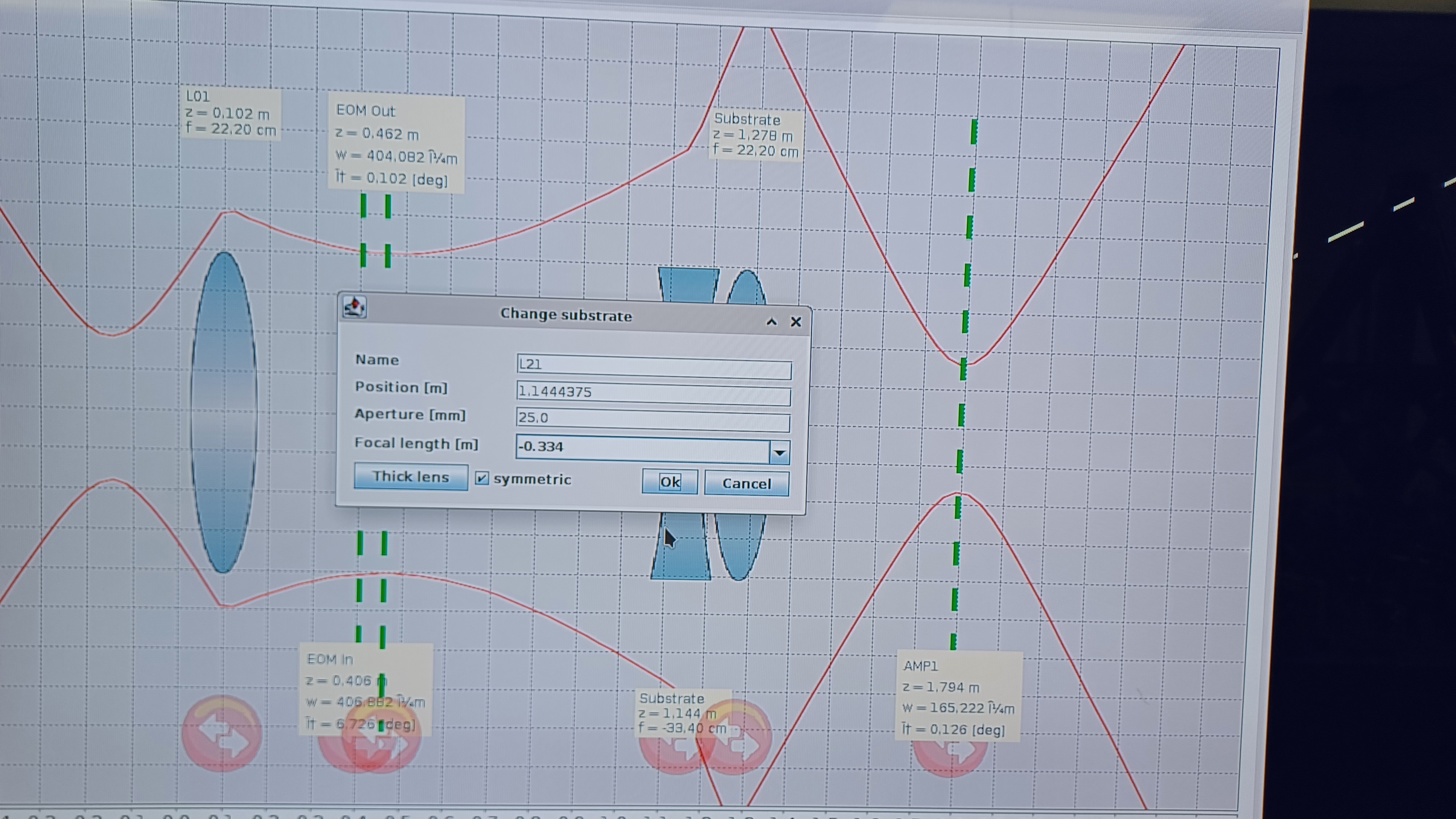
Using this we got a preliminary mode matching solution in JamMT, using the same lenses we used for NPRO SN 1661, so we installed it. I managed to get a picture before JamMT crashed on us, see first attachment. Before tweaking mode matching we checked our polarization into Faraday isolator FI01. We have ~1.602 W in transmission of FI01 with ~1.701 W input, a throughput of ~94.2%. We then proceeded with optimizing the mode matching solution. It took several iterations (7, to be exact), but we finally were able to get the beam waist and position correct for Amp1 (the target is a 165 µm waist 60mm in front of Amp1, or 1794.2mm from the NPRO):
To finish, we set up a temporary PBSC to check that the polarization going into Amp1 was vertical w.r.t. the PSL tabletop. We put a power meter in transmission of the temporary PBSC and adjust WP02 to minimize the transmitted power; the lowest we could get is 0.41 mW (with a roughly 1.6 W beam) in the wrong polarization, which matches what we had during the most recent NPRO swap, so we were good to go here. We forgot to measure the final lens positions before leaving the enclosure, we will do that first thing tomorrow morning. The new NPRO is now set, aligned, and mode matched to Amp1 and we will continue with amplifier recovery tomorrow.
We left the NPRO running overnight with enclosure in Science mode; the first shutter (between the NPRO and Amp1) is closed.
Using the lockloss page, I picked out some times when the tag "IMC" or "FSS_OSSCILATION" was triggered. Then, I just made some simple time series comparison plots between several PSL channels and PSL PEM channels. In particular, the PSL channels I used were:
H1:PSL-FSS_FAST_MON_OUT_DQ, H1:PSL-FSS_TPD_DC_OUT_DQ, H1:IMC-MC2_TRANS_SUM_IN1_DQ, H1:PSL-PWR_NPRO_OUT_DQ, H1:PSL-PMC_MIXER_OUT_DQ, H1:PSL-PMC_HV_MON_OUT_DQ. I compared those to the following PSL PEM channels:
H1:PEM-CS_ACC_PSL_PERISCOPE_X_DQ, H1:PEM-CS_ACC_PSL_PERISCOPE_Y_DQ, H1:PEM-CS_ACC_PSL_TABLE1_X_DQ, H1:PEM-CS_ACC_PSL_TABLE1_Y_DQ, H1:PEM-CS_ACC_PSL_TABLE1_Z_DQ, H1:PEM-CS_ACC_PSL_TABLE2_Z_DQ, H1:PEM-CS_MIC_PSL_CENTER_DQ. For this analysis, I've only looked at 3 time periods but will do more. Below are some things I've seen so far:
From my very limited dataset so far, it seems like the most interesting area is where the PSL_PERISCOPE_X/Y and PSL_TABLE1_X/Y/Z channels are located.
For the same 3 time periods, I checked if the temporary magnetometer H1:PEM-CS_ADC_5_18_2K_OUT_DQ witnessed any glitches that correlate with the IMC/FSS/PMC channels. Attached are some more time series plots of this. During the time period on September 13th, I do not see anything interesting in the magnetometer. However, during the other two periods in November I do see a glitch that correlates with these channels. The amplitude of the glitch isn't very high (not as high as what is witnessed by the periscope_x/y and table1_x/y/z channels), but it is still there. Like in the original slides posted, I don't see any correlations with the PWR_NPRO channel with any glitches in the pem channels on any of the days.
WP12214
Marc, Ryan C, Dave:
h1susex has been fenced from Dolphin and powered down in preparation to re-establishing the LIGO DAC 28ao32 as the driver of the ETMX L1/L2 and ESD channels, essentially undoing what was done on Tuesday.
Marc has completed the cable move, h1susex is powered back up.
All watchdogs have been cleared, Ryan is recovering SUSTEMX, SUSTMSX and SUSETMXPI.
Thu21Nov2024
LOC TIME HOSTNAME MODEL/REBOOT
13:37:36 h1susex h1iopsusex
13:37:49 h1susex h1susetmx
13:38:02 h1susex h1sustmsx
13:38:15 h1susex h1susetmxpi
Fil is borrowing one of the PEM adc channels I was borrow for the Guralp 3T huddle testing. He unplugged one of the horizontal readbacks from the Guralp on ADC4, leaving the other 2 dofs plugged in. Channel he connected to is ADC 4 28, H1:PEM-CS_ADC_4_28_2K_OUT_DQ.
Sheila and I spent some time today trying to calibrate the PMC channels into units of frequency so we can compare the glitches seen by the PMC with other channels. Peter's alog comment last night (81375) leads us to understand the glitches are around 2 kHz in frequency, so above the PMC bandwidth. Therefore, we want to calibrate the PMC error signal.
Luckily for us, Jeff Kissel recently did some PMC scans to determine the PMC PZT Hz/V calibration for a different purpose, alog 73905 (thanks Jeff!). We used his DTTs to determine the time it took to scan one FSR, see screenshot. We determined that it took 0.52 seconds to scan one FSR, and the scan rate is approximately 6.75 V/s (we know the PZT is nonlinear, but we figure this estimate is good enough for our purposes). This gives us 3.51 V/FSR on the PZT, or 0.0236 V/MHz, using the FSR = 148.532 MHz from T0900616.
We are still thinking about how to calibrate the PMC mixer signal.
Daniel calibrated the PMC mixer signal using the PMC PDH signal, lho81390.
H1:PSL-PMC_MIXER_OUT_DQ calibration is 1.25 Vpp / 1.19 MHz (fwhm) = 1.05 V / MHz.
See his note about H1:PSL-PMC_MIXER_OUT_DQ: "the channel recorded by the DAQ has a lot of gain and clips around +/-80mV, but it is calibrated correctly" compared to live traces on an oscilloscope.
2024 Nov 12
Neil, Fil, and Jim installed an HS-1 geophone in the biergarten (image attached). HS-1 is threaded to plate and plate is double-sided taped to the floor. Signal given was non-existent. Must install pre-amplifier to boost signal.
2024 Nov 13
Neil and Jim installed an amplifier (SR560) to boost HS-1 signal (images attached). Circuitry checked to ensure signal makes it to the racks. However, when left alone there is no signal coming through (image attached, see blue line labelled ADC_5_29). We suspect the HS-1 is dead. HS-1 and amplifier are now out of LVEA, HS-1's baseplate is still installed. We can check one or two more things, or wait for more HS-1s to compare.
Fil and I tried again today, we couldn't get this sensor to work. We started from the PEM rack in the CER, plugging the HS1 through the SR560 into the L4C interface chassis, confirming the HS1 would see something when we tapped it. We then moved out to the PEM bulkhead by HAM4, again confirmed the HS1/SR560 combo still showed signal when tapping the HS1. Then we moved to the biergaren and plugged in the HS1/SR560 right next to the other seismometers. While watching the readout in the DAQ of the HS1 and one of the Guralps I have connected to the PEM AA, we could see that both sensors could see when I slapped the ground near the seismometers, but the signal was barely above what looks like electronics noise on the HS1, while the Guralp showed lots of signal that looked like ground motion. We tried gains from 50-200 on the SR560, none of them really seemed to improve the snr of the HS1. The HS1 is still plugged in over night, but I don't think this particular sensor is going to measure much ground motion.
One check for broken sensors - A useful check is to be sure you can feel the mass moving when the HS-1 is in the correct orientation. A gentle shake in the vertical, inverted, and horizontal orientations will quickly reveal which orientation is correct.
Promised details from the final day of the NPRO swap.
Summary
Mode Matching Lens Positions
We first measured the new positions of mode matching lenses L02 and L21, I'll update the As-Built table layout with the new values. The new positions:
Amplifier Recovery
With the previous day's work resulting in the NPRO being ready for amplifier recovery, this is where we started our recovery work. Amplifier recovery was straightfoward. As a reminder, we first measure the power into the amp and the unpumped power out, to assess our intial alignment. Then we raise the amp pump diode operating current in 1A intervals until we get to the locking point, adjusting beam alignment into the amplifier at each step in current (so alignment follows the formation of the thermal lenses in the amplifier crystals). For Amp1 we had 1.612 W input and an unpumped output of 1.252 W. This is 77.6% throughput, which is above our requirement of 65% throughput before starting to pump the amplifier, so we proceeded with recovery of Amp1 (see Amp1 columns in below table). We finished Amp1 recovery with ~70.2 W output, so we calibrated the Amp1 power monitor PD to this value (was off by a couple Watts). We then lowered the light level in the Amp1/Amp2 path (using the High Power Attenuator (HPA) after Amp1) and checked alignment, all looked good. We increased the Amp2 seed with the HPA to ~1.8 W and checked the unpumped output from Amp2. This measured at ~1.5 W, which is ~83% throughput and above our 65% threshold, so we proceeded with recovery of Amp2. This also went very well, see the Amp2 column in the below table; we had ~64.0 W output from Amp2 with an ~1.8 W initial seed power (the power was bouncing between 63.9 W and 64.0 W). With Amp2 fully powered we then used the HPA to increase the Amp2 seed to max, which resulted in ~140.2 W output from Amp2.
Stabilization System Recovery
PMC: After lunch we began recovering the PSL stabilization systems in order: PMC, ISS, FSS. We began by using the HPA after Amp2 to lower the power to ~100 mW to check our beam alignment up to the PMC. All looked good here so we increased the power to max and measured the power incident on the PMC at ~129.4 W. We then toggled the PMC autolock to ON and it locked without issue. We needed to use the picomotor-equipped mirrors (M11 and M12 on the layout) to tweak the beam alignment into the PMC, but were only able to get ~102.0 W in transmission with ~27.0 W in reflection. This is 9 W more than we had after our last NPRO swap, indicating that we really need to take a look at PMC mode matching; since we still had more than enough power to deliver to the IFO we decided to defer the mode matching work to a later Tuesday and continue with PSL recovery. The PMC Trans and Refl monitor PDs were calibrated to the newly measured values; they were pretty close to begin with, but were still 1-2 W different than our power meter was measuring. We then returned the amplifer pump diode currents to their previous operating values (9.0 A and 8.8 A for Amp1, 9.1 A and 9.1 A for Amp2), which lowered Amp1 output power from ~70 W to ~68 W and Amp2 output power from ~140 W to ~139 W; this also changed PMC Refl to ~24 W and PMC Trans to ~104 W, indicating our beam is better matched to our current mode matching solution at these pump diode currents.
ISS: Moving on to the ISS, we first measured the amount of power in our 1st order diffracted beam (the "power bank" for the ISS). With the loop off and the AOM diffracting a default of 4% we expect ~5.7 W in this beam, and this is what we measured. AOM alignment was good, so moved on to the ISS PDs in the ISS box. A voltmeter get plugged into the DC Out ports on the ISS box and a HWP inside the box is adjusted until PD voltages read ~10.0 V. We did this, but noticed the DC voltage reading on the ISS MEDM screen was much higher, ~12.5 V for PDA and ~13 V for PDB. We tried to lock the loop and, as expected with PD voltages that high, the loop thought it needed to removed more power from the beam and ran the diffracted power up really high. We immediately unlocked the ISS and began looking into what could be the problem, as the MEDM reading on the ISS PDs generally matches the voltmeter reading (I say "generally matches" because, for reasons unknown to me, the ISS does not use the DC out from its PDs, it uses a Filter out and "derives" the DC and AC PD voltages from that). The PDs appeared to be working correctly, and we found no large dark voltages that would indicate a PD failure/malfunction. When we unplugged the Filter output the PD reading in MEDM began to slowly climb, but when we blocked the light onto the PDs the MEDM reading went to zero. Looking back at trends we saw the PDs behaving as expected before this most recent NPRO swap, only reading these higher values in MEDM with the relock of the PMC an hour or so prior. I had never seen this behavior in the past, so wasn't quite sure where the problem could be. Thinking maybe something had gone wrong in either the ISS inner loop servo box or maybe something in the CER, we called Fil and asked if he could take a look at the CER electronics for the ISS while we moved on to FSS recovery. It was at this point we found the problem. When the FSS MEDM screen was opened the first thing we saw was one NPRO noise eater (NE) light green, and the other red. The green light was our NE enable monitor, indicating that the NE toggle was switched ON in the PSL software; the red light was our NE monitor, which reads the Check output from our NPRO monitor PD that indicates whether or not the NPRO's relaxation oscillation was being supressed. So we had the NE toggled ON but it was clearly not working, so we toggled it off and on again. The NE monitor went green and the channel monitoring the relaxation oscillation indicated it was working properly, and the ISS PD values on the ISS MEDM screen now read the correct values. So I learned that we have another measure of if the NE is working or not, the ISS PD readings on the MEDM screen go higher. Trending back, the NE stopped working at ~16:58 PST on Thursday, right before Ryan and I left the enclosure for the day. We'll keep an eye on this, as right now it's not clear why the NE turned off. At this point everything looked good for the ISS so we moved on to the FSS.
FSS: For the FSS, we first tried to see if the RefCav would lock with the autolocker; it would not. We had to manually tune the NPRO temperature to find a RefCav resonance, one was found with a slider value of ~ +0.06. The temperature search ranges were adjsuted to this new value and we tried the autolocker again. While we could see clear flashes the autolocker would not grab lock for some reason. The FSS guardian was paused so it would stop yanking the gains around upon lock acquisition, but this did not help, the autolocker refused to hold lock for some reason. So I did it manually (from the FSS manual screen, manually change NPRO temperature until a resonance flashed through, then really quickly move the mouse up to turn the loop on; if the loop grabs go back to the FSS MEDM screen and turn on the Temperature loop, if not then turn the loop off and try again), which worked. With a locked RefCav we measured a RefCav TPD voltage of ~ 0.84 V. The RefCav Refl spot looked pretty centered so we did not do any alignment tuning. This completed our work in the enclosure so we cleaned up, turned the computers and monitors off, left the enclosure, and put it into Science mode. Outside, we scaned the NPRO for mode hop regions and measured TFs of the stabilization loops.
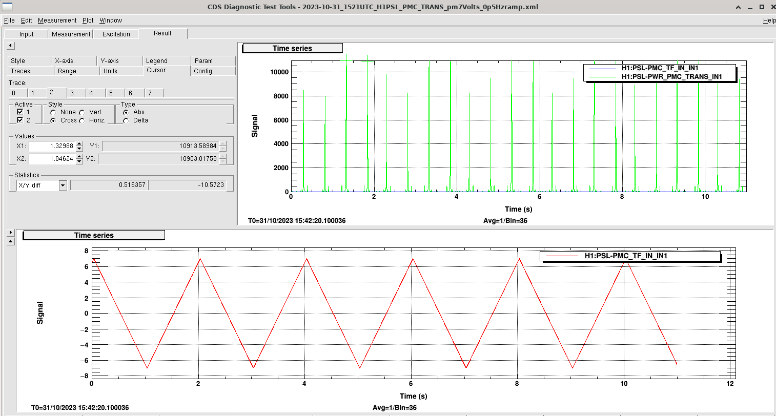
NPRO Temperature Scan
Now outside the enclosure we set up to scan the NPRO temperatures to check for mode hopping. We took the HV Monitor output from the PMC fieldbox to trigger an oscillscope on the PZT ramp and used the PMC Trans PD to monitor the peaks. We set the PMC's alignment ramp to +/- 7.0 V and a 1 Hz scan rate, and monitored the peaks as we tuned the NPRO crystal temperature. We used the slider on the FSS Manual MEDM screen, which gives us a total range of approximately +/- 0.8 °C (0.01 on the slider changes the NPRO crystal temperature by roughly 0.01 °C and the slider goes from -0.8 to +0.8). Since we were close to zero on slider, sitting at ~ +0.07, we started by moving lower (which reduces the NPRO crystal temperature); our starting crystal temperature, as read at the NPRO power supply front panel, was 24.22 °C. We got all the way to the negative end of the slider, which gave a crystal temperature of 23.38 °C, and did not see any evidence of mode hopping on the way down. Heading back up we finally started to see early evidence of mode hopping near the top end of the slider; we could clearly see a new forest of peaks show up in the PMC PZT scan and one of them started to grow noticebly as the temperature was further increased. This mode hop region began at a crystal temperature of 24.76 °C, and the slider maxed out at 24.91 °C. At this point we still had not fully transitioned through the mode hop region, but we did have a peak starting to grow very large indicating that we were almost there. Since we saw no evidence of mode hopping by making the temperature colder, we went back to our starting place of 24.22 °C and then reduced the temperature further to the next RefCav resonance below that; this resulted in a crystal temperature of 23.96 °C at a slider value around -0.17. Again I had to lock the RefCav manually, as the autolocker did not want to grab and hold lock. With all of the stabilization systems locked we moved on to TF measurements.
Transfer Functions and Gains
We started with the PMC. With the current settings we have a UGF of ~1.6 kHz and 60° of phase margin, see first attachment. Everything looked good so we left the PMC alone.
For the ISS, we have a UGF of ~45 kHz and a phase margin of 37.5°, see second attachment. Again, everything look normal here so we left the ISS alone.
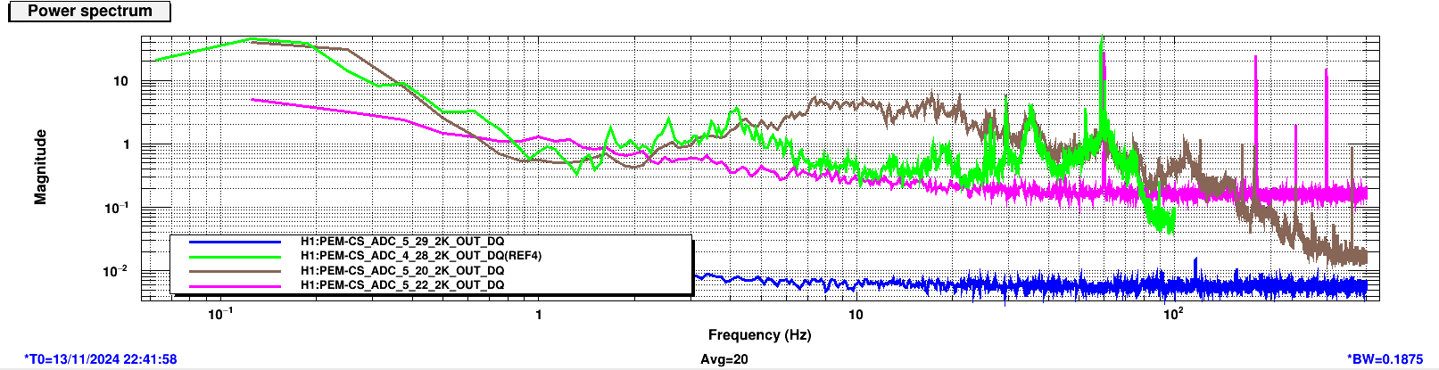
For the FSS, we started with a Common gain of 15 dB. Everything looked OK, but since we had seen some potential zero crossings that like to hide in the longer range scans we did a "zoomed in" scan from 100 kHz to 1 MHz. Sure enough, there were a couple peaks in the 500 kHz to 600 kHz range that were pretty close to a zero crossing. We lowered the Common gain to 14 dB to move them away from the potential crossing; the third attachment shows this zoomed in area with the Common gain at 14 dB, and the peaks in question are clearly visible. With this Common gain we have a UGF of ~378 kHz with ~60° of phase margin, see fourth attachment; we took this TF out to 10MHz to check for any weirdness at higher frequency and did not see anything immediately concerning. To finish we took a look at the PZT/EOM crossover (around 20 kHz) to set the Fast gain. The final attachment shows this measurement (a spectrum of IN1) at a Fast gain of 5 dB; this looks OK so we left the Fast gain as is.
At this point the NPRO swap was complete, the PSL was fully recovered, and we handed things over to the commissioning team for IFO recovery. We still need to look at PMC mode matching, and will do so during future Tuesday maintenance periods. This closes WP 12210.