[Stefan and Kiwamu] (Translated by J. Kissel)
Approximately 2 months ago (see alog 7490), Stefan and Kiwamu modified the output matrix of the IMC's ASC control system, such that the caviy-axis-basis ("DOF" basis) alignment is decoupled with the input pointing alignment.
Jeff K. asked me to write some more details for the procedure of how we did it 
Here it is, translated by Jeff.
The procedure of the adjustment :
- Lock IMC and engage all the IMC ASC loops.
-
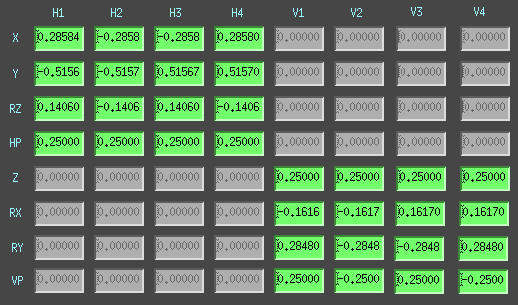
Make sure the output matrix is as follows
- DOF1 feeds to just MC2 (1.0)
- DOF2 feeds to MC1 and MC3 (+,+0.5 for Pitch and +,-0.5 for Yaw)
- DOF4 has all zeroed elements
- There is only one non-zero element in the DOF3 drive matrix namely H1:IMC-OUTMATRIX_P(Y)_4_3. (Computing the rest of the elements is our goal.)
-
Make sure the input matrix is as follows
- DOFs 1 and 2 are a derived by a linear combination of WFSA and WFSB
- DOF 3 is only measured by MC2 TRANS (1.0).
- DOF4 has all zeroed elements
We're going to use the closed-loop, control output signals for these cross-coupled, cavity-axis-basis, loops as our metric of where the cross-coupled sensors think the cavity axis lies. We will then offset the error point of DOF3 (which controls the input pointing, with the PZT) at DC, to see how this affects all our controlled degrees of freedom (again at DC). Before we get started, there is some residual DC value of this control signal because the static alignment had not yet been tuned, and the integrators in the loops found the best spot for us. To make things easier to calculate later, we can offload this DC alignment control signal to the mirror/actuator basis (after the output matrix that we're trying to make better), such that the cavity-axis-basis control output signal is zero at DC. We have a script that already does this:
-
/opt/rtcds/userapps/release/ioo/h1/scripts/imc/mcwfsrelieve- This moves the DC output control signal from H1:IMC-DOF_1(2, 3)_P(Y)_OUTPUT to H1:IMC-MC1(2,3)_PIT(YAW)_OFFSET and H1:IMC-PZT_PIT(YAW)_OFFSET.
- Now the control output for all three DOFs is zero (or close to zero with some fluctuation since the servos keep running).
-
Introduce a small offset at the DOF3 error point in either YAW of PIT (Let's say we do this in PIT)
- We introduced an offset of 0.2 in H1:IMC-DOF_3_P_OFFSET, which moves the PZT, changing the input pointing
- This shifts the error point of the DOF3 loop such that it is parked at -0.2.
- But ALSO, it changes the alignment of the input pointing and therefore of the MC REFL beam on WFSA and WFSB
- WFSA and WFSB interpret this as the cavity axis changing, which inform DOF1 and DOF2
- So DOF1 and DOF2 loops move all the mirrors to move in order to realign the cavity eigen axis to where they think it should be.
-
Record the newly accumulated, static offset in all three control signals after all the servos settle down
- This is H1:IMC-DOF_1/2/3_P_OUTPUT
-
We have only introduced an offset in DOF3, and we *want* it to only control DOF3. So, we take the control output of DOF1 and DOF2, and compute the [DOF3 > MC1], [DOF3 > MC2], and [DOF3 > MC3] matrix elements of the output matrix to make this true, which "diagonalizes" the cavity-axis-basis. We do so with some maths:
- DOF3 > MC1 = (DOF2 OUTPUT) / [DOF2 > MC1] * [DOF3 > PZT] / (DOF3 OUTPUT )
- DOF3 > MC2 = (DOF1 OUTPUT) / [DOF1 > MC2] * [DOF3 > PZT] / (DOF3 OUTPUT )
- DOF3 > MC3 = (DOF2 OUTPUT) / [DOF2 > MC3] * [DOF3 > PZT] / (DOF3 OUTPUT )
-
(or in channel form)
- H1:IMC-OUTMATRIX_P_1_3 = (H1:IMC-DOF_2_P_OUTPUT) / ( H1:IMC-OUTMATRIX_P_1_2) * (H1:IMC-OUTMATRIX_P_4_3 ) / (H1:IMC-DOF_3_P_OUTPUT)
- H1:IMC-OUTMATRIX_P_3_3 = (H1:IMC-DOF_2_P_OUTPUT) / ( H1:IMC-OUTMATRIX_P_1_2) * (H1:IMC-OUTMATRIX_P_4_3 ) / (H1:IMC-DOF_3_P_OUTPUT)
- H1:IMC-OUTMATRIX_P_2_3 = (H1:IMC-DOF_1_P_OUTPUT) / ( H1:IMC-OUTMATRIX_P_2_1) * (H1:IMC-OUTMATRIX_P_4_3 ) / (H1:IMC-DOF_3_P_OUTPUT)
- Turn off the DOF3 pitch offset, enter in these values, and DOF3_PIT is done. (We keep the mirror/actuator basis offsets in place, because this is what the original loops said was the best alignment and we want to consistently return there regardless of whether the cavity-axis-basis loops are on or off.)
- Move on to YAW and do the same process in YAW.

