· BSC1 - ITMY
o ISI + HEPI - Unlocked, Previously commissioned. Performance Spectra
· BSC2 - BS
o ISI + HEPI - Unlocked, Previously commissioned. Performance Spectra
· BSC3 - ITMX
o ISI : Chamber-Side testing complete. Report validated. Ready for cartridge install.
o HEPI : Locked. Model is running. Electronics ready for turn on.
· BSC9 - ETMX
o ISI : Locked. Chamber-Side testing complete. Report Validated. Cartridge installed.
Needs balancing
o HEPI : Unlocked, ongoing initial alignment.
· BSC10 - ETMY
o ISI : Currently installed in BSC6. Will be pulled out and installed in BSC10. Payload (SUS) will be moved then. Electronics are disconnected
o HEPI : Unlocked.
HAM 1
o HEPI: Locked (09/18/13) and vented.
Low priority testing
One L4C needs to be replaced: H2
One actuator is weak: V4 It is 20% weaker than its counterparts. Likely clogged. May require replacement further down the line.
· HAM2
o ISI: previously commissioned with HEPI locked (recent performance spectra - not calibrated in higher frequencies), currently unlocked, in vacuum
o HEPI - IPS position loops and alignment offsets installed - recent performance spectra
Unlocked 07/23
· HAM 3
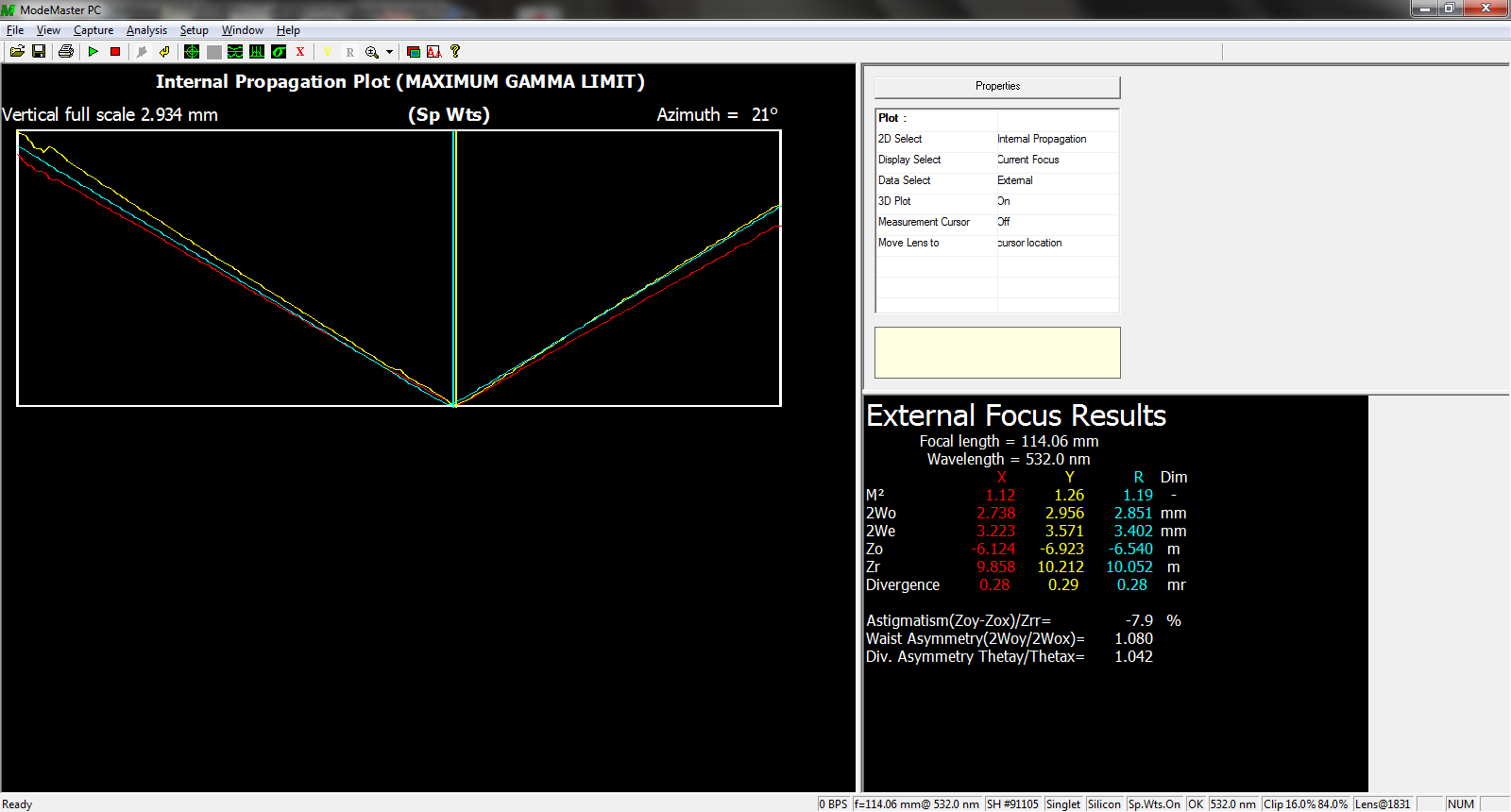
o ISI: previously commissioned with HEPI locked (recent performance spectra - Calibrated), currently unlocked, in vacuum
Sensor correction installaton started.
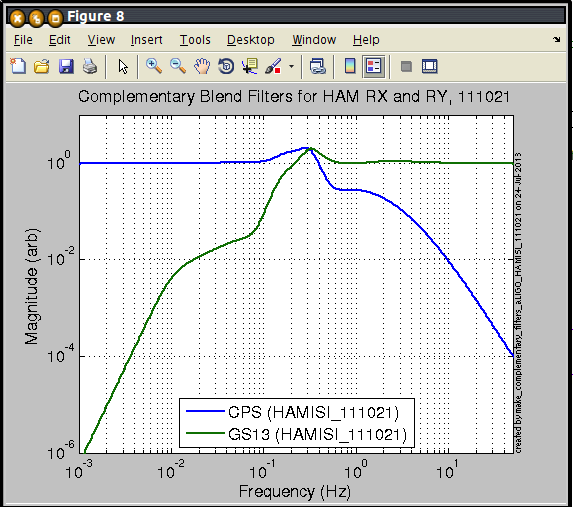
New blend filters installed. aLigo Blend filters on all DOF but RX and RY. eLigo high roll off blend filters on RX and RY. Performance Spectra.
o HEPI - IPS position loops and alignment offsets installed - recent performance spectra
Unlocked 07/23
· HAM 4
o ISI: In chamber, Previously tested during assembly validation, currently locked, no suspension installed, in-vac cables not connected.
Electronics ready, in field cables ready, in-rack cables ready. Temporary STS cables
Model is running, and MEDM screens are available in the Sitemap.
o HEPI: Currently locked, to be commissioned
Electronics ready, in field cables ready, in-rack cables ready. Temporary STS cables
Model is running, and MEDM screens are available in the Sitemap.
· HAM 5
o ISI: In Chamber, Previously tested during assembly validation, currently locked, no suspension installed, in-vac cables not connected,
Chamber temporarily closed.
Electronics ready, in field cables ready, in-rack cables ready. Temporary STS cables
Model is running, and MEDM screens are available in the Sitemap.
o HEPI: Currently locked, to be commissioned
Electronics ready, in field cables ready, in-rack cables ready. Temporary STS cables
Model is running, and MEDM screens are available in the Sitemap.
· HAM 6
o ISI:
in chamber.
Unlocked, no SUS
Mechanical adjustments complete
Initial in-chamber testing complete, but not validated yet
o HEPI: Unlocked - Ongoing commissioning
· Guardian:
Transition scripts ready
Transition scripts work under guardian interpreter
alarm.txt files ready
snap files ready


