david.barker@LIGO.ORG - posted 10:23, Thursday 30 April 2026 (90071)
Thu CP1 Fill
Thu Apr 30 10:06:27 2026 INFO: Fill completed in 6min 24secs
Images attached to this report

Thu Apr 30 10:06:27 2026 INFO: Fill completed in 6min 24secs
TITLE: 04/30 Day Shift: 1430-2330 UTC (0730-1630 PST), all times posted in UTC
STATE of H1: Planned Engineering
OUTGOING OPERATOR: None
CURRENT ENVIRONMENT:
SEI_ENV state: MAINTENANCE
Wind: 4mph Gusts, 2mph 3min avg
Primary useism: 0.07 μm/s
Secondary useism: 0.14 μm/s
QUICK SUMMARY: Several projects continue today, including surveying of the BS on the test stand and setting up new electronics for the BBSS.
Yesterday, Betsy had turned the HAM3 QPD chassis back on after having it off for replacement of the chamber feedthru, and comparing at least the NSUMs of ASC POP A and B to before the chassis was turned off, the levels are a little lower and a bit noisier (see attached).

State of CDS
We are currently running with some RED on the Overview, these are:
1. h1suslo12 (BBSS) has its DACKILL part triggered
2. Removed h1susbs IPC senders are causing some IPC receive errors
3. BSC2 SWWD has SEI tripped
4. Pending SPI filter load

a-Plus O5 SUS BSC2 HAM3 HAM4 (susb2h34) System Wiring Diagrams - D2300383
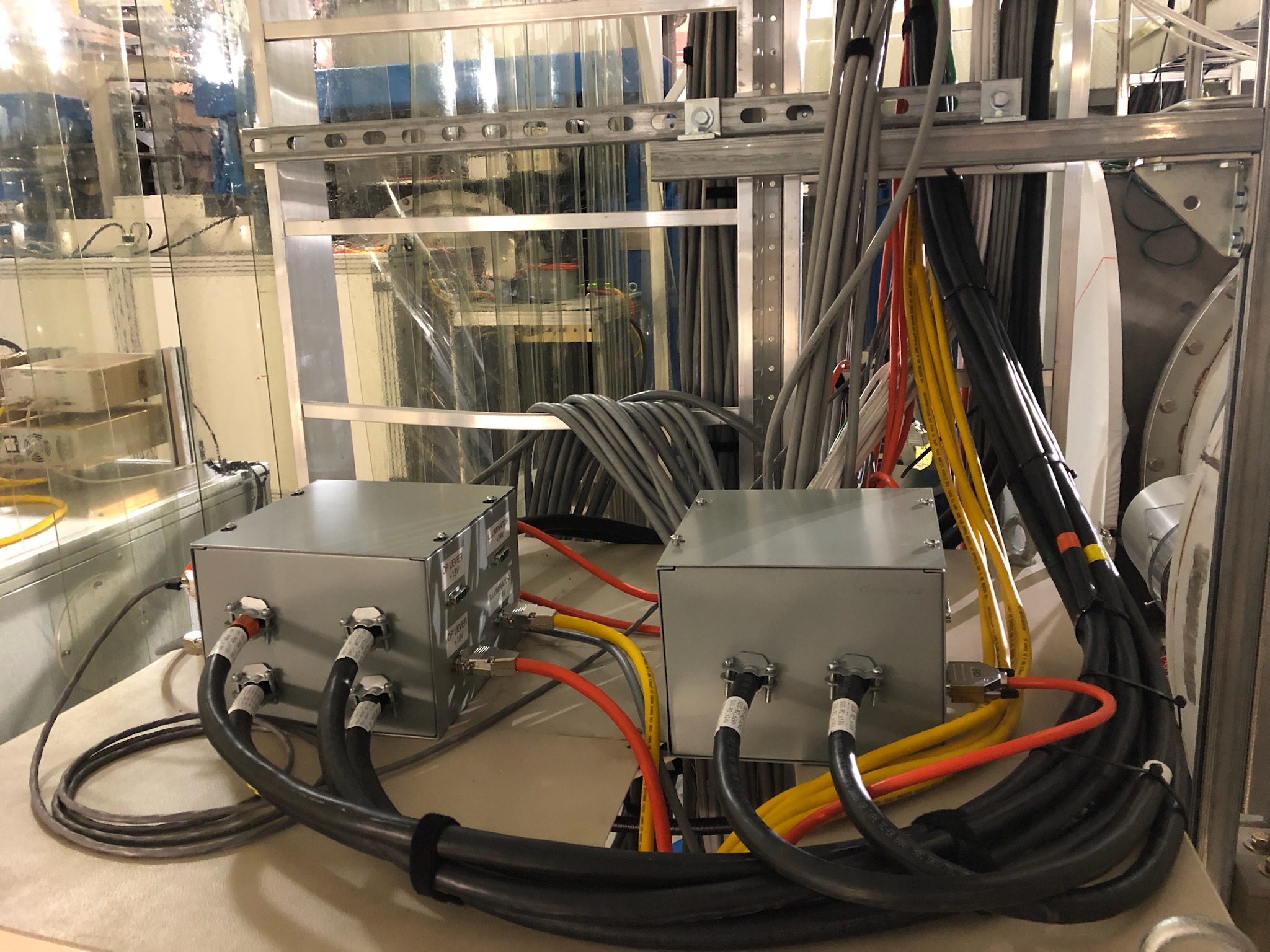
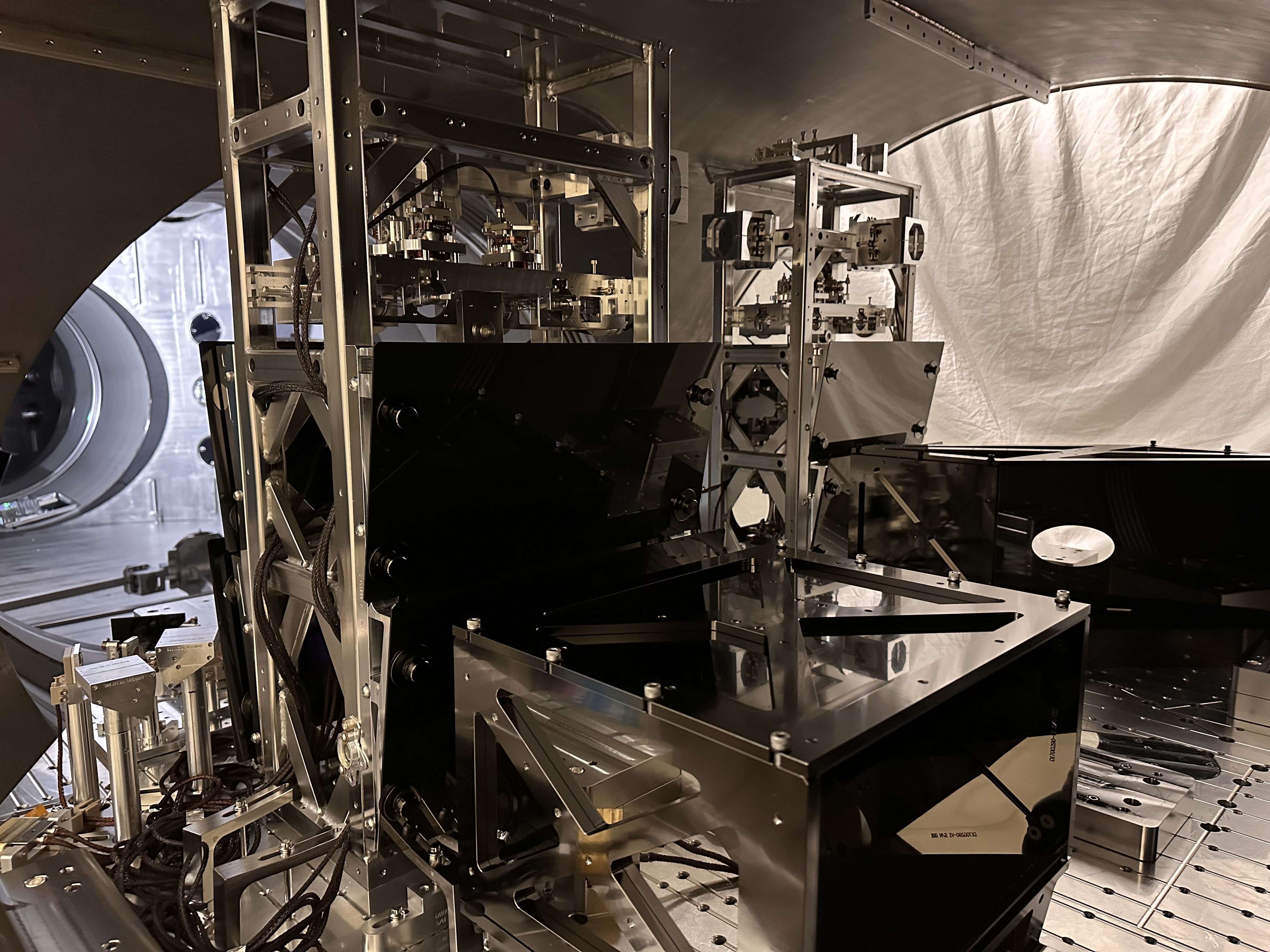
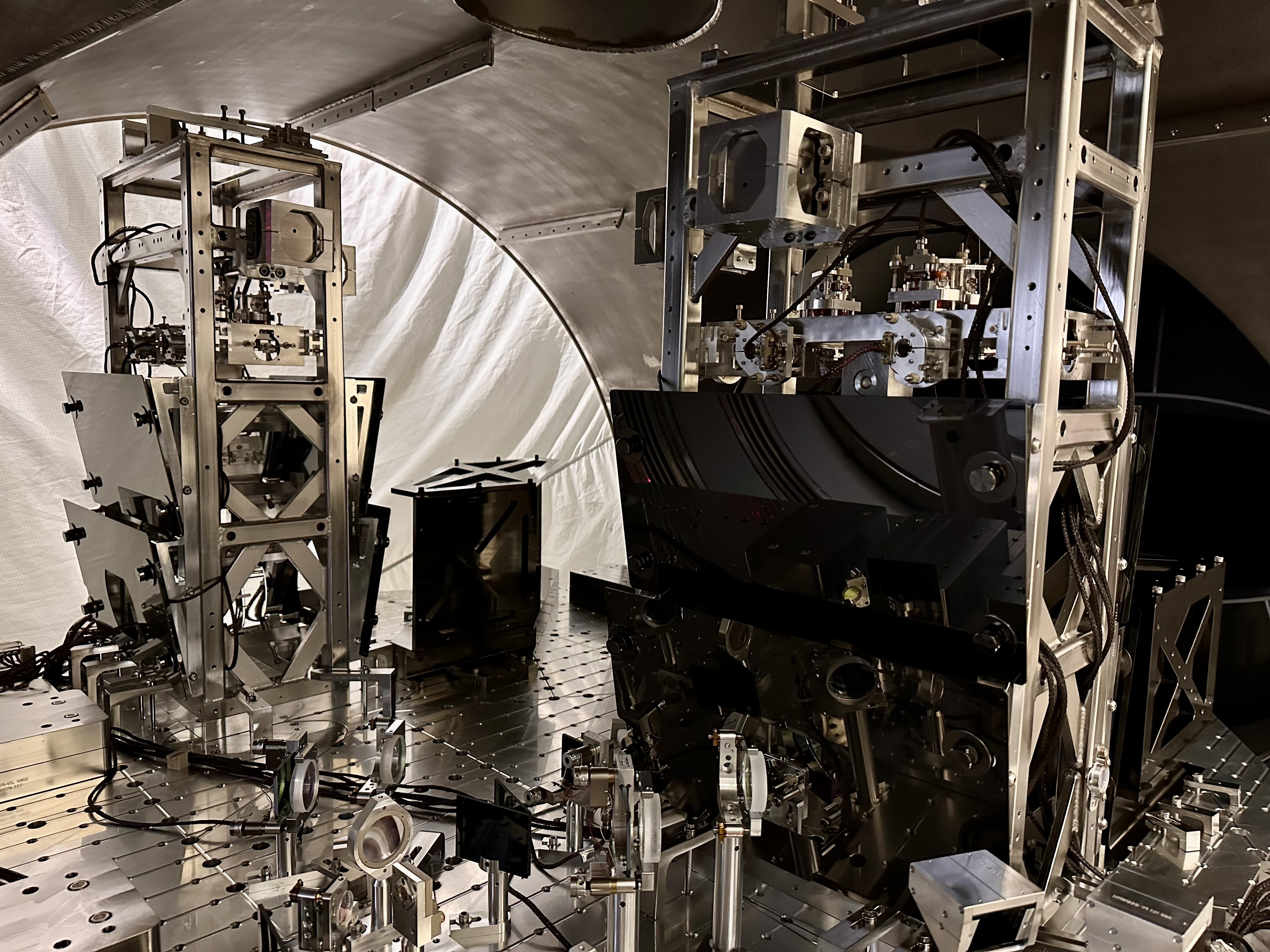
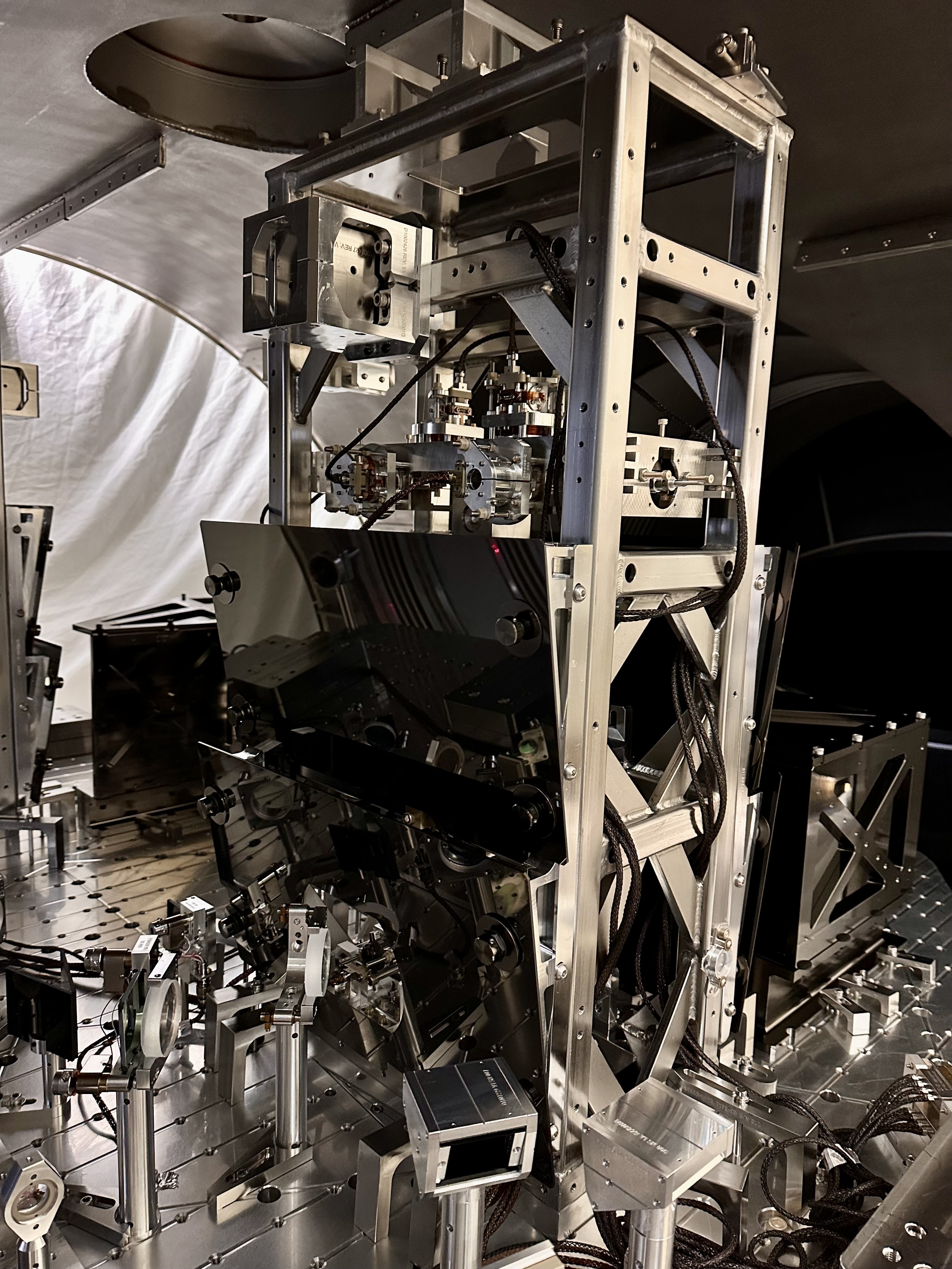
Electronics and cabling for BSC2 and HAM3 suspensions (BBSS, LO1, LO2) completed per D2300383. The new HAM-A and Triple Acquisition Drivers were left powered off (BS Bot, LO1, LO2).
Four Kepco supplies were installed in the CER Mezzanine. Supplies provide power to the SUS-R2 rack. A second junction box was added to SUS-R2. They have been set to ±18V and ±24V, shared between SUS and SPI
Final dressing of the field cables going from the biergarten to the West Bay Mechanical Test Stand completed. They will be used for testing of the old and new BS. Some cable swapping in the CER is required for testing the QOSEMs (some old BS electronics will be reused).


I connected the temp cables which Fil routed for us to the BS Satellite Boxes in the rack in the biergarten.  I disconnected the "to chamber" cables on the Sat amps and connected our temps to those.  After some resorting of the BS Top Stage BOSEM cabling at the ISI, I was able to get the appropriate signals from the appropriate 6 BOSEMs on the medm.
I am not sure that we will reuse these cables but for the record (since I couldn't find an old BS alog with this info), the Cable Bracket on the ISI is stuffed with these D1000225 cables:

S1106798 Against ISI (Top floor) - BS F1, F2, F3, LF
S1106797 Middle floor - RT, SD
S1104787 Lowest floor - M2 - medm no longer connected tho, says Oli - not plugged in right now anyways

We have more trending to do tomorrow but the F1, 2, 3 Face BOSEMs seem to be "in deeper" while the LF, RT, SD DOFs all show about nominal OSEM position from when it was in the chamber a few days ago.  Chewing on what this means wrt the structure position and ISI/Test Stand level, etc.
M2 cable is unplugged, but if plugged in, we would see the readbacks for that stage on the BBSS M2 stage. So still would be possible to get some info
Note, I also had to partially uncover the front of the ISI to get the cables out and pinned in such a way to connect to the mock feedthru and then dirty cables.


WP13200 Tony and I reattached the bellows between ISCT1 and HAM1.
TITLE: 04/29 Day Shift: 1430-2330 UTC (0730-1630 PST), all times posted in UTC
STATE of H1: Planned Engineering
INCOMING OPERATOR: None
SHIFT SUMMARY: More surveying was done on the BS on the test stand, and electronics were connected to that the suspension can be damped.
LOG:
| Start Time | System | Name | Location | Lazer_Haz | Task | Time End |
|---|---|---|---|---|---|---|
| 14:37 | FAC | Kim | LVEA | - | Technical cleaning | 17:54 |
| 14:37 | FAC | Randy | LVEA | - | Work on HAM5/6/7 cleanroom | 18:30 |
| 15:41 | AOS | Betsy | LVEA | - | Walkabout | 15:58 |
| 16:08 | SUS | Fil | LVEA/CER | - | QOSEM susrack work | 18:46 |
| 16:32 | IAS | Jason, Ryan C | LVEA | - | BS FARO surveying | 19:15 |
| 17:00 | AOS | Mitchell | LVEA | - | Checking totes by HAM6 | 17:32 |
| 17:55 | FAC | Kim | EX | - | Technical cleaning | 19:15 |
| 18:25 | SEI | Jim | LVEA | - | Replacing spring on BSC2 HEPI | 19:10 |
| 18:29 | AOS | Mitchell | LVEA | - | Bagging parts for LLO | 18:51 |
| 18:40 | ISC | Elenna, Sheila | Opt Lab | - | BHSS build | 19:45 |
| 19:46 | SEI | Jim, Randy | LVEA | - | Replacing spring on BSC2 HEPI | 20:17 |
| 19:59 | SUS | Oli | CER | n | Checking BS cabling | 20:47 |
| 20:12 | SUS | Fil | LVEA/CER | - | QOSEM susrack work | 21:41 |
| 20:18 | FAC | Randy | FCES | - | Forklifting a table to hi-bay | 21:08 |
| 20:30 | VAC | Travis | LVEA | - | Finishing HAM3 feedthru | 21:41 |
| 20:42 | IAS | Jason, Ryan C | LVEA | - | BS FARO surveying | Ongoing |
| 21:02 | SUS | Betsy | LVEA | - | BS surveying | 23:05 |
| 21:11 | SUS | Oli | LVEA/CER | - | Check in w/ Fil | 21:19 |
| 21:18 | VAC | Jordan | LVEA | - | Staging parts by CP1 | 21:38 |
| 22:04 | SUS | Tom, Oli | LVEA | - | QOSEM electronics | 23:15 |
| 22:21 | ISC | Sheila | LVEA/Opt Lab | - | Looking for laptops | 22:33 |
| 22:24 | AOS | Mitchell | LVEA | - | 22:35 | |
| 22:40 | ISC | Camilla | LVEA | - | ISCT1 bellows, putting away parts | Ongoing |
| 23:00 | AOS | Travis | LVEA | - | Check in w/ Betsy | 23:05 |
| 23:02 | AOS | Mitchell | LVEA | - | 23:06 | |
| 23:15 | ISC | Tony | LVEA | - | ISCT1 bellows | Ongoing |
FAMIS 39862 Vibration Sensors To Gauge Health Of HVAC Fans Site Wide


I had a look at the three SRC gouy phase measurements listed in 88155, this is related to commissoning modeling git issue 33
To do this, Evan Hall helped get me started using the current version of finesse (3.13.13) in the control room. Anyone can use this conda environment by using conda activate finesse.
In the first plot, the upper left subplot shows the cold gouy phase measurement, which is reasonably close to the finesse prediction using nominal parameters from the LHO_O4.yml. I've added traces to show what happens when the SR3 ROC and SR2 ROC are changed by the rss error given by Garilyn, +/-6mm for SR3 and +/-3.7mm for SR2, and varied the distance between SR2 and SR3 around the value in the finesse yml. The gray band shows the measurement result, indicating that the gouy phase measurement could be explained by the nominal ROCs if the SR3-2 distance is longer than the value used in finesse by 3mm, or if the distnace is nominal the SR3 ROC could be shorter by 6mm to explain the measurement.
The next two panels show the two measurements made in October 2019, before the ITM replacement (52638 and 52658). The ring heaters were on for both of these measurement, decreasing the expected gouy phase, and central heating was also on which should increase the gouy phase. Using the TCS actuation strengths from 90004 we cannot easily explain these measurements as compatible with the cold state measurement.
The last panel shows the impact of each indivdual TCS actuator on the gouy phase measurement. The fact that all these lines are fairly close to parallel suggests that a series of measurements where we change only one actuator at a time could be a useful check of the actuation strengths.
In the second attached plot, I plotted the difference in gouy phase between having the heater on and off, which we can get from the comparison of the two 2019 measurements, with various parameter changes. I was wondering if we could use this difference to get information about the SR3-SR2 distance if we trust the HWS measurement of the SR3 heater strength. The 1.8 degree systematic uncertainty on the gouy phase measurements is large enough to make this seem not very promising.
The script used to make these plots is in the commissoning modeling repo here commit 8635b914


WP13209 Add DUST LVEA3 to EDC for trending
Ryan C, Jonathan, Dave:
The EDC+DAQ were restarted to add DUST LVEA3 channels. A new H1EPICS_DUST.ini was created with a modified create_edcu_dust_ini_file.py script.
Before the full DAQ restart Jonathan took the opportunity to install new code on FW2.
There were no issues with the DAQ restart.
Tagging OPS. Counts for the dust monitor inside the cleanroom at the test stand (LVEA West bay, currently housing the BSC2 cartridge) are now trendable.

Dave, Jeff, Oli
Model-wise, BSFM is good to damp for IAS work and the QOSEMs are ready to test using the BBSS overview screen found on the sitemap under BS / ITM -> BBSS (temp). Channel names for the old beamsplitter (BSFM) are the same, and channel names for the BBSS are 'SUS-BBSS'. This is temporary - once the BBSS is installed, its model will overwrite the current BSFM model.
Yesterday Betsy, Jeff, Tom, and I came up with a plan for how we want to test out the BBSS, QOSEMs, and build up the BBSS infrastructure while keeping the BSFM (currently on the test stand) damped for now. The plan can be found at T2600169.
The first part of the plan required figuring out how to split up the BSFM electronics with the BBSS in a way that allowed us to keep damping the BSFM while also having sufficient electronics for testing the QOSEMs. I built up a temporary BBSS model called h1susbbss.mdl and compared it to the h1susbs.mdl, as well as using the 2026 google slides in G2301306 to compare the ADC and DAC lineup for the BSFM vs BBSS.
Model needs
BSFM
M1: Damping aka ADC and DAC
M2: Not needed
M3/OPLEV: Oplev not needed
BBSS
M1: Readbacks for QOSEMs aka ADC
M2: Not fully necessary
M3/OPLEV: Not fully necessary
M1
Since we needed to have damping available for the BSFM, we needed to keep the ADC to BSFM M1 as well as the BSFM M1 to DAC how it's been. Luckily, the BBSS M1 QOSEMs use different ADC channels, so we can still have readbacks for the QOSEMs. The readouts are supposed to go to the same DAC channels as the BSFM M1 readouts, so I've terminated these outputs, but that's okay since we won't be wanting to drive the coils for a bit. After BSFM work is done, we will be putting the BBSS on the test stand and taking transfer functions with BOSEMs first, so this setup also means that we'll be able to use the BSFM model (WITH DIFFERENT OSEM2EUL MATRIX VALUES) to take those measurements before needing to swap to driving those CDs/DACs with the QOSEMs instead. The QOSEM connections were done according to the proper order of F1 F2 F3 SD LF RT (D080273). The BOSEM connections in the BSFM model were NOT changed, and so are currently F1 F2 F3 LF RT SD.
M2
Regarding M2 for each suspension, we don't need M2 on the BSFM anymore, so I've taken those ADC and DAC connections away. I've connected them to the BBSS model though. We obviously don't need them now but they will be good to have already ready.
M3 / OPLEV
Similar to M2, on the BSFM I've disconnected the ADC -> OPLEV connections since we don't need them anymore. For the BBSS, I connected up M3 OSEMs, but I did not connect the ADC -> OPLEV since the channels that the OPLEV uses with the BBSS are the same as the first four channels of ADC -> BSFM M1, which we still want.
To make sure the BBSS model channels would be named correctly, I renamed the BBSS block from BS to BBSS. I also removed any IPC channels in the BBSS model that will be needed in the future, and also removed these IPC channels from the BSFM model to be safe, even though it probably would've been fine.
Updating h1susbs model
h1susbs was updated with the changes listed above (r35127), built, and installed. before vs now
Turning "h1suslo12" into "h1suslo12 but actually it's for the BBSS/QOSEMs"
h1susb2h34 has a model running called h1suslo12, meant to be for LO1 and LO2. Since neither of these suspensions are currently needed, Dave decided it would be easiest to install the BBSS model as an updated h1suslo12 model instead of removing h1suslo12 and replacing it with h1susbbss. To do this all we needed to do was change the dcuid in h1susbbss to h1suslo12's dcuid of 188, and then copy h1susbbss over to overwrite h1suslo12. h1suslo12 was built and installed with these changes (r35136). before vs now
Dave documented installing these models in 90043.
Guardian notes (tagging GRD and OPS):
The SUS BS guardian has been STOPPED to keep it from doing anything weird. Please leave it stopped. There is no SUS BBSS guardian, and we don't want there to be. We will be controling both suspensions manually.


Wed Apr 29 10:08:08 2026 INFO: Fill completed in 8min 4secs
The D3 feedthru on HAM3 was swapped from the 3-port version with 3x Dual DB25 feedthrus to the single piece 12x DB25 connector feedthru. We re-attached the in-vac cables that were originally in that port and Betsy re-attached the in-air cables so that the SUSes can be controlled overnight.
Cables were unplugged on both the vac and air sides, so keeping track was a bit tedious.  I have started an AS-BUILT cheatsheet which tracks the serial numbers as we go on the main LHO HAM3 Flange Layout DCC page https://dcc.ligo.org/D1002874-v10, see the google doc.  Attached is a snapshot of the sheet with the D3 work logged so far.
TBC...
Note, for the 24hours that this feedthru work and recabling was happening, I turned off the chassis that powers this ISC/IO_245 cable to POPA/POPB at the transimpedence amp SLot U25 of the ISC_R4 rack near the PSL (Thanks Kissel for the consult to get me there). Per Fil, the picomotors had already been "turned off" when their plug in was disconnected at the ISCT2 picomotor "box", so I didn't do anything for that one.
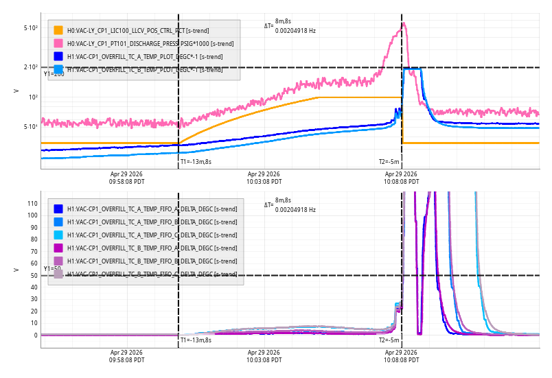
Last week I tripped the HEPI pump controller valving out the BSC2 actuators, it took me until today to try to recover it. In the process of investigating this I found that one of the 4 corner station HEPI pump carts has been more or less off since a power outage in December. The remaining pump stations have been running at about 95% drive to cover for the lost cart. I am working on some revisions to the famis and asking to Tony to add a verbal notification if there is a mismatch in the manifold pressures for the 4 corner pump stations.
Nice to know that we have overhead to lose one pump station and still supply the corner HEPI with pressure. Drive is much lower now that all 4 are running again.
Attached image shows how long we have been running with only 3 pumps. Crosshair in the upper left plot shows approximate time of the power outage. Bottom right shows we have been running at ~1900 cts drive out of 2048 total available since then. We are back around 1100 cts drive now.

I've added a message to DIAG_MAIN and to VerbalAlarms to "Check HEPI pump station pressures" if any of the four CS pump stations manifold pressures are more than 5% different than any other (this threshold may need to be updated in the future if we find it's too tight, but right now it's okay). All updates committed to svn.
The channels being used for this comparison are H1:HPI-PUMP_L0_PS{1,2,3,4}_PRESS1
Mitchell, Rahul
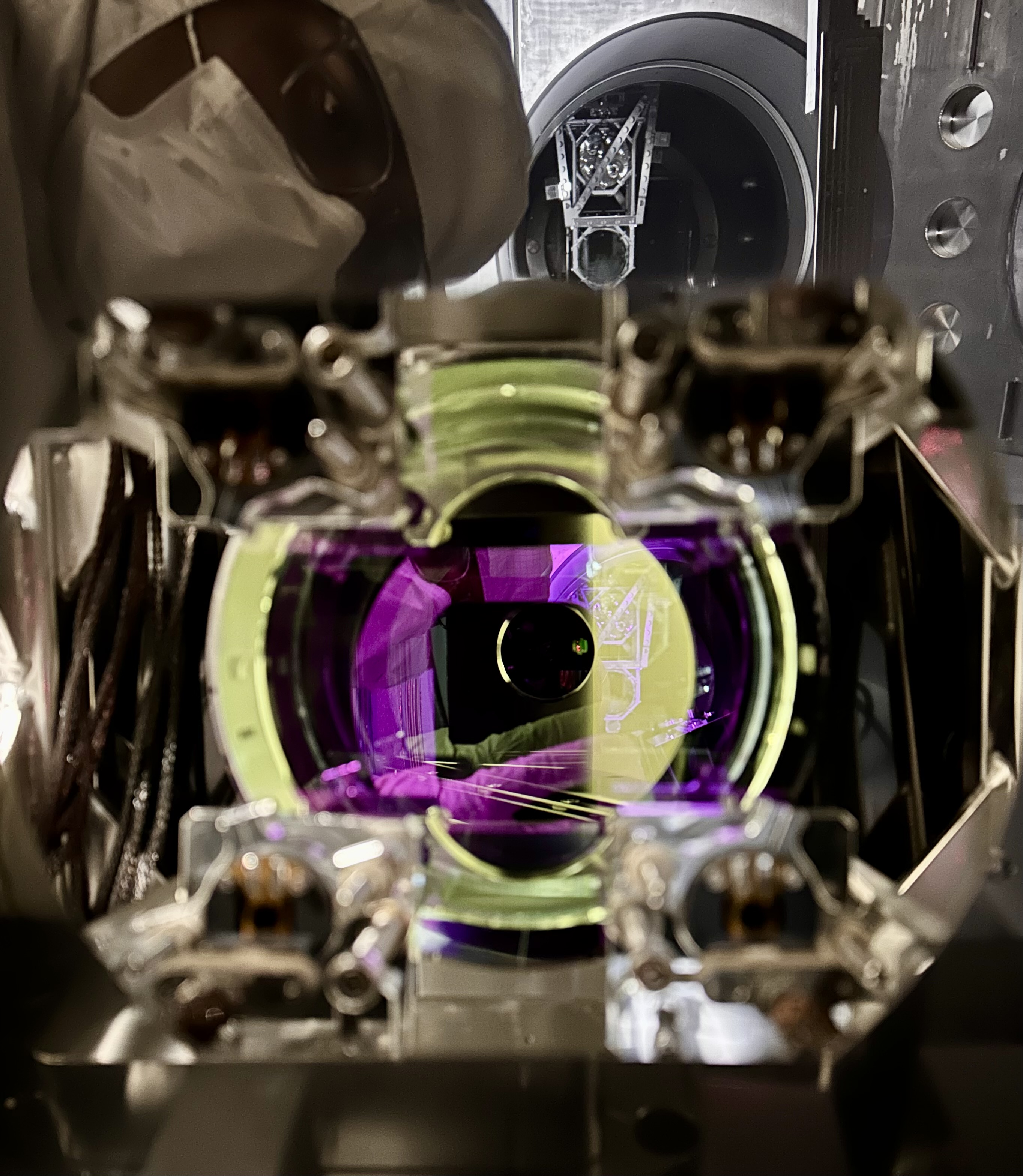
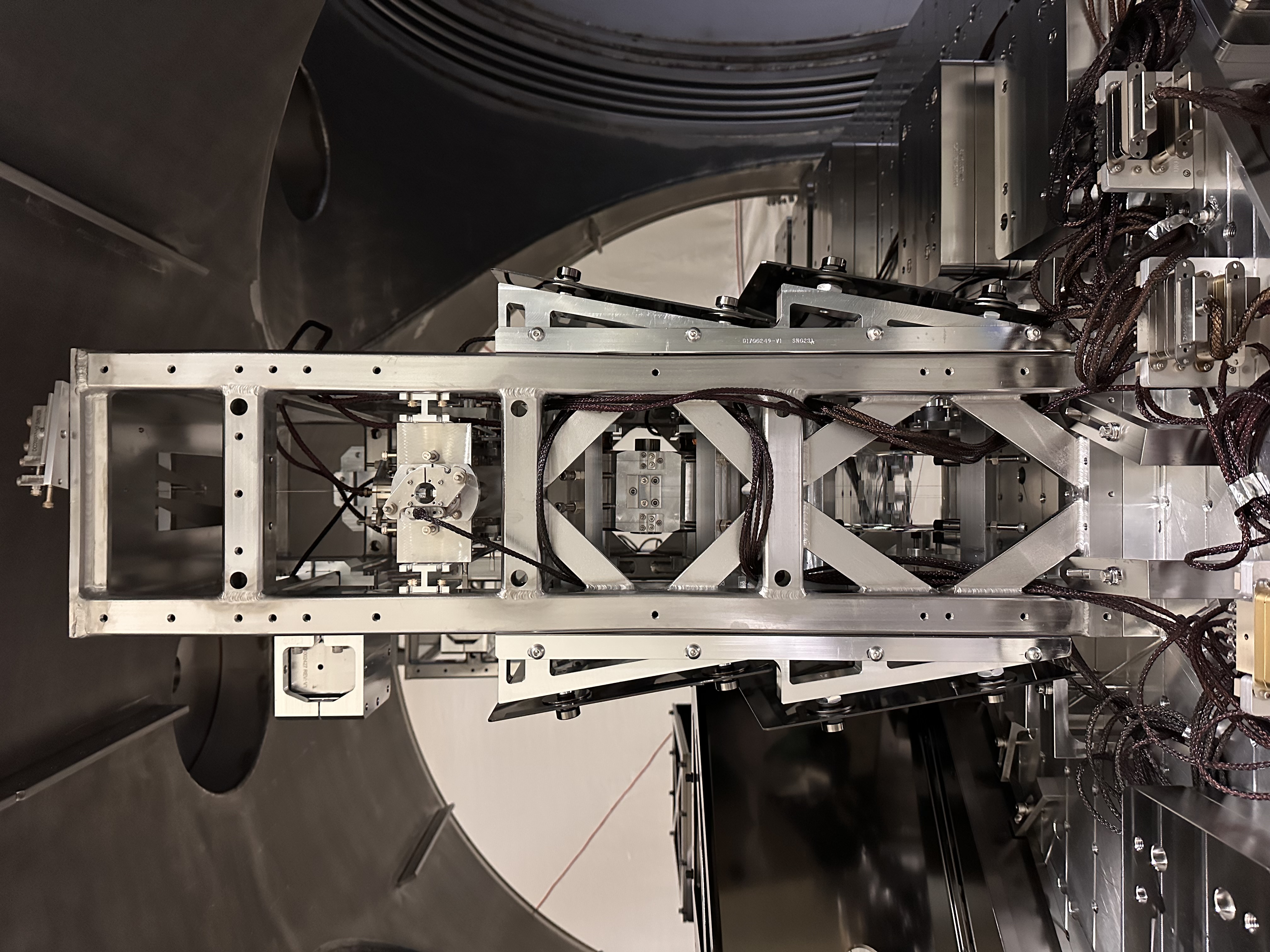
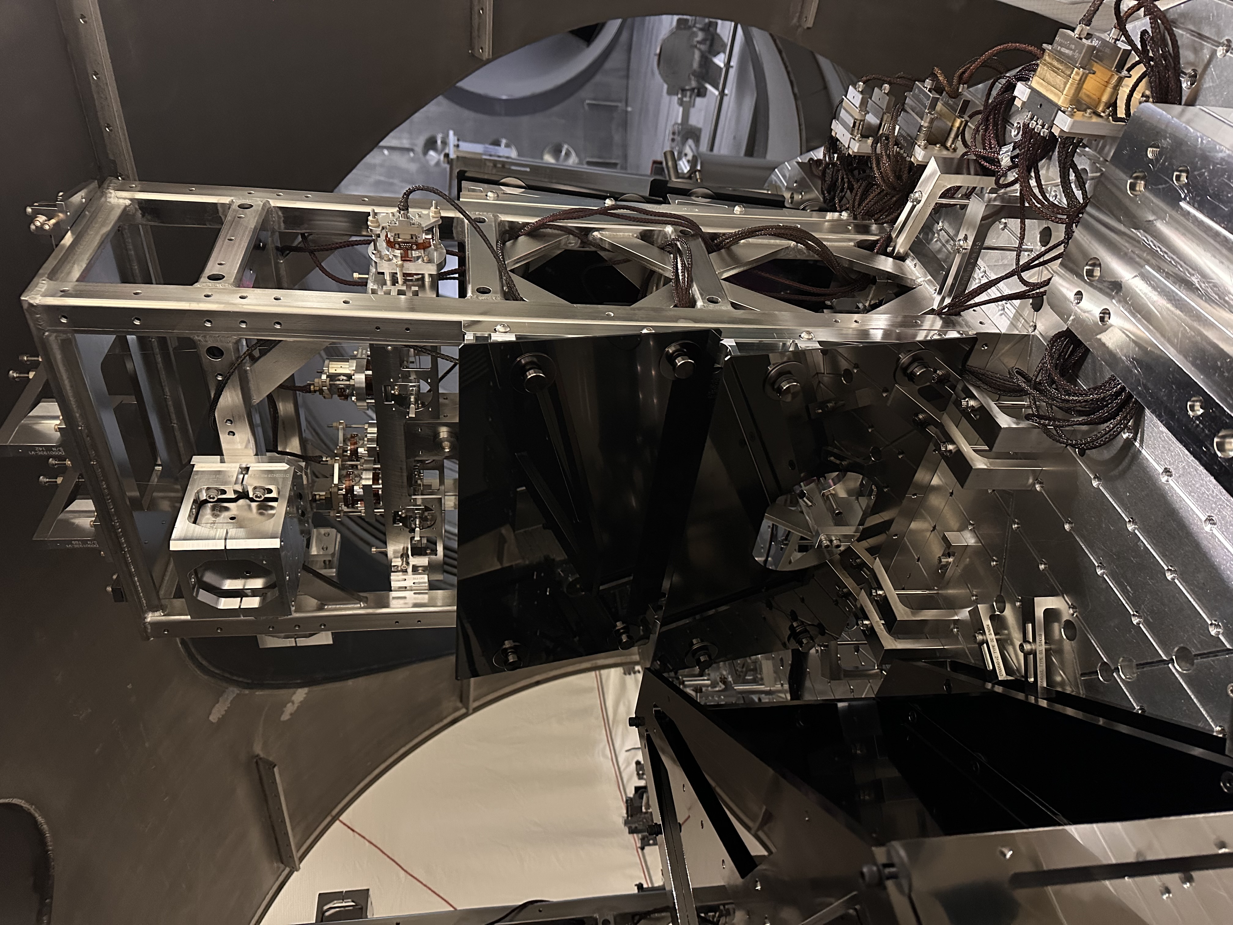
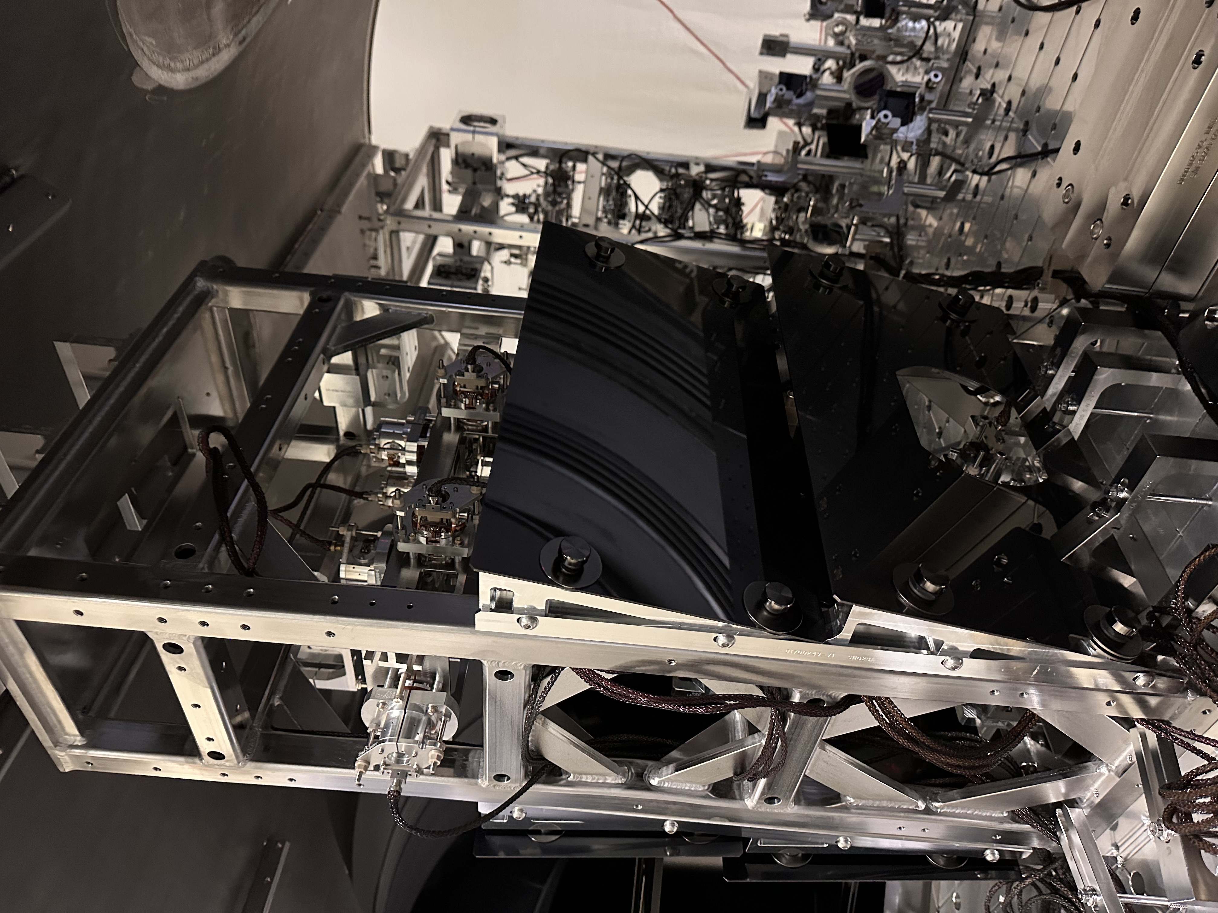
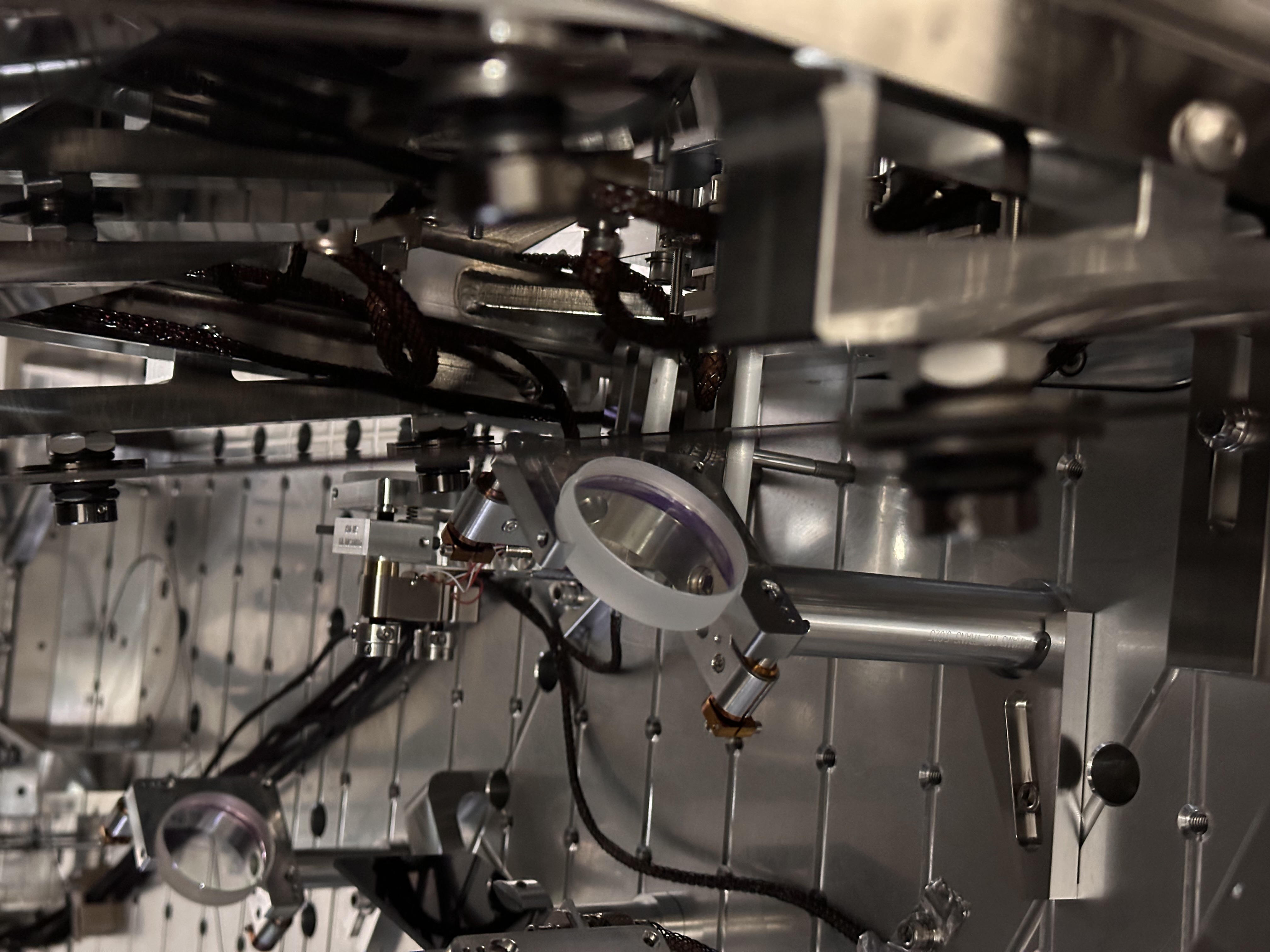
This morning we entered HAM3 chamber and attached the baffles (for stray light control) to both PR2 (HSTS) and MC2 (HSTS) suspensions. The baffle assembly design is shown D1700257_V5. These baffles were attached (directly mounted on the HSTS structure) on both the sides of the optic, i.e HR and AR side.
Before attaching the baffles I inspected both the optics and they looked nice and clean, hence didn't needed any First Contact cleaning.
I am attaching pictures below for reference.
We found that both PR2 and MC2 had two missing 1/4-20 threads on the HR side for attaching the mounting rail (D1700249_v1) of the baffle (Mitchell will attach a picture showing the same). Typically, these rail need four holes on the structure for securing them. However, we used the lower two threaded holes for attaching these mounting rail and they were rigidly secured. On the DCC I found that both PR2 and MC2 have D020023_V3 of the HSTS_Structural Weldment Assembly, latest D020023_V7 has more holes on the frame.
We also noted that one of the Siskiyou mount is very close to the MC2 baffle (AR side) as shown in the picture here. However, I can confirm that they are not touching and there is a decent amount of clearance between them.
I still need to perform health checks on both the suspensions to rule out any rubbing and will post the results as a comment over here.
Note - counts on dust monitor were in single digit before and after entering/exiting the chamber (Thanks to Ryan C for arranging this).


WP13211 closed.
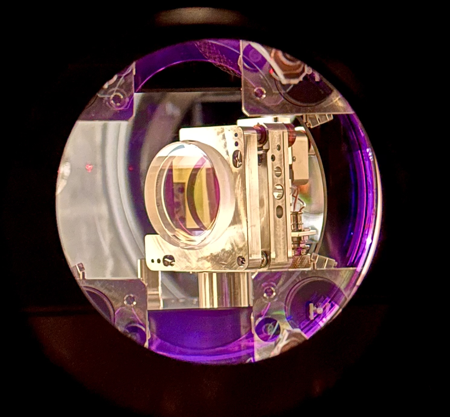
Pictures of the HR side of PR2. No upper mounting holes for the HRST Baffle rail.


Note:- All the mounting holes looked centered and they aligned nicely and we found no issues (except the one mentioned above) during installation.
IIET ticket filed - https://services1.ligo-la.caltech.edu/FRS/show_bug.cgi?id=37761
One D2600143 bracket was installed on the door side of MC2 and PR2. These bracets were installed due to lack of upper holes in the cage for mounting the baffles rails.
B&K tests can be found in alog 90905. Additional brackets can be installed later if they are needed.
These brackets should fufill FRS 37761


