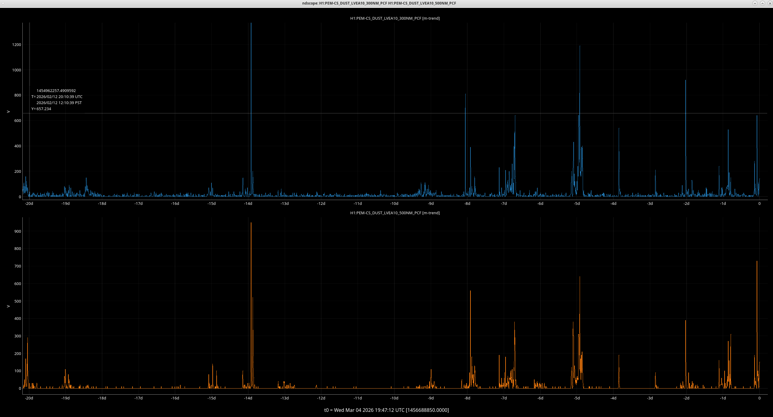
I took the .5-800hz tfs last night on HAM1 ISI, to see if the 70hz feature was improved by the periscope brace. Short version, it has been and I now see the ~170hz that I measure here. There's also a feature at ~102hz that could be a number of things, but I didn't see that in the B&K measurement of the periscope+stiffener.
First attached image are the L2L gs13 tfs I took last night. Data below .5hz is from measurements I took last year, I don't expect those to have changed. Above .5hz is new data. These new measurements were taken with HEPI locked, so features around the pier modes at 15hz might not be permanent. I might also get better resolution above 200hz when the pumpdown is done and it's a little quieter at the chamber.
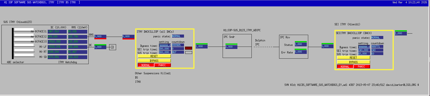
Second image are the data from last year, after adding the viton to the periscope dog clamps. That viton is still in place, but we now also have the stiffener added, so the sharp feature at 70hz is now moved to 170hz.
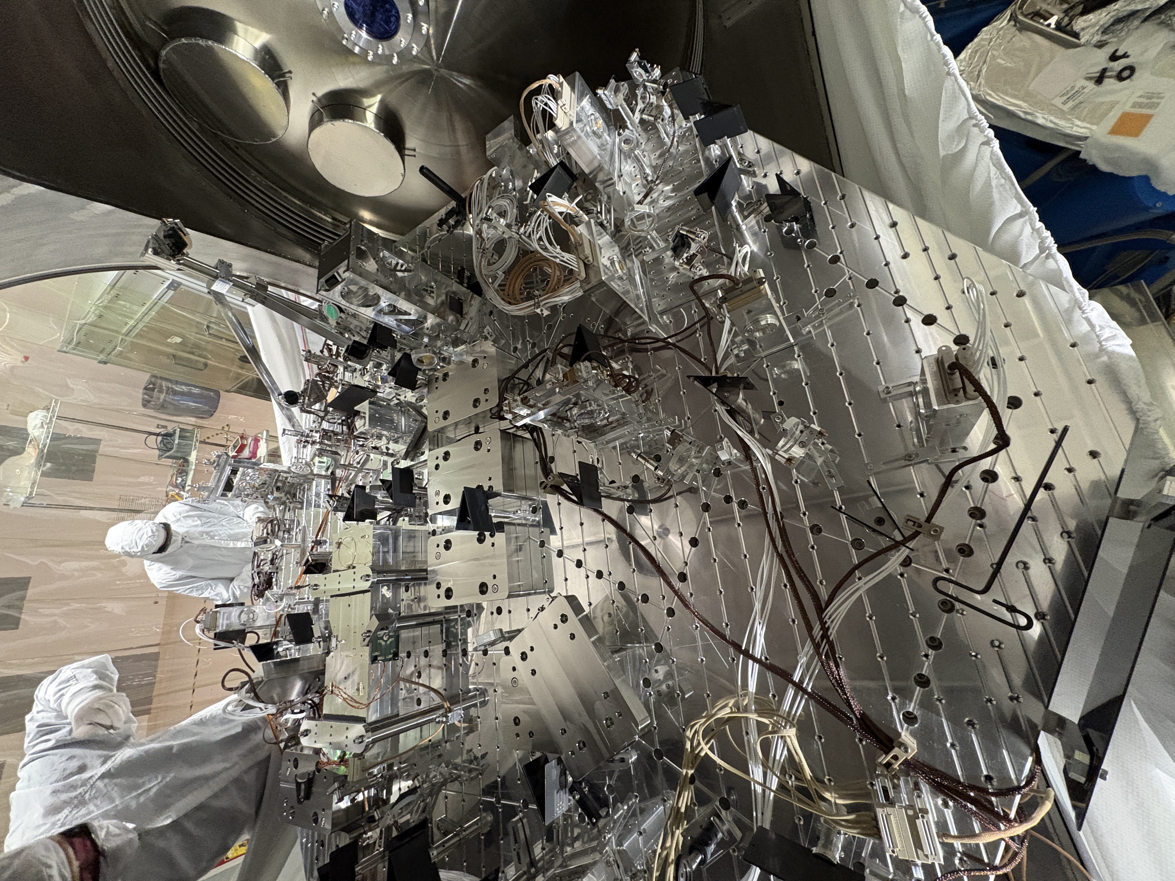
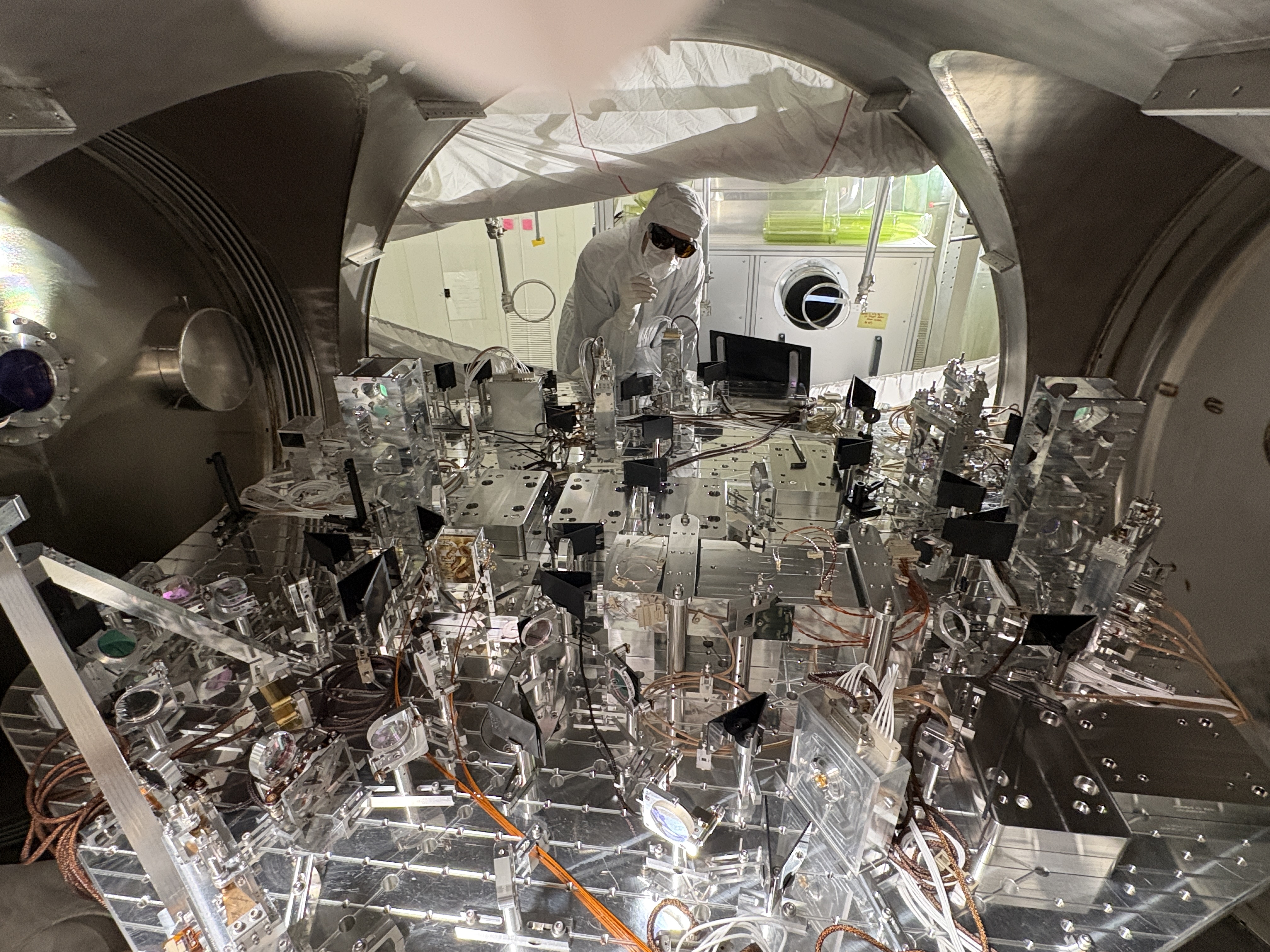
Third and fourth images are the CPS tfs. These are harder to compare because HEPI was unlocked for the fourth image (june 2025 tf) and locked for the third (last night).
I will post C2C tfs when I get there. Hope to see if I can increase the loop gain on HAM1 with the 70hz feature gone, we'll see.


These are the gs13 c2c tfs. First image is the data from last night, second image is the data from last year. Similar story, the new tfs look a little easier to wrap loops around, but the 170hz feature will require some notching. There is also still some feature at 75hz in the X and Z dofs. Hmm.


I've touched up the isolation loops, removing the 70hz notches where I could and increased ugfs to more normal levels, from 22hz before to 25-30 hz. This should mostly help below 10hz.


