jeffrey.kissel@LIGO.ORG - posted 15:43, Wednesday 08 April 2026 - last comment - 16:11, Wednesday 08 April 2026(89825)
SPI Cable Installation Status: Essentially Ready to Go
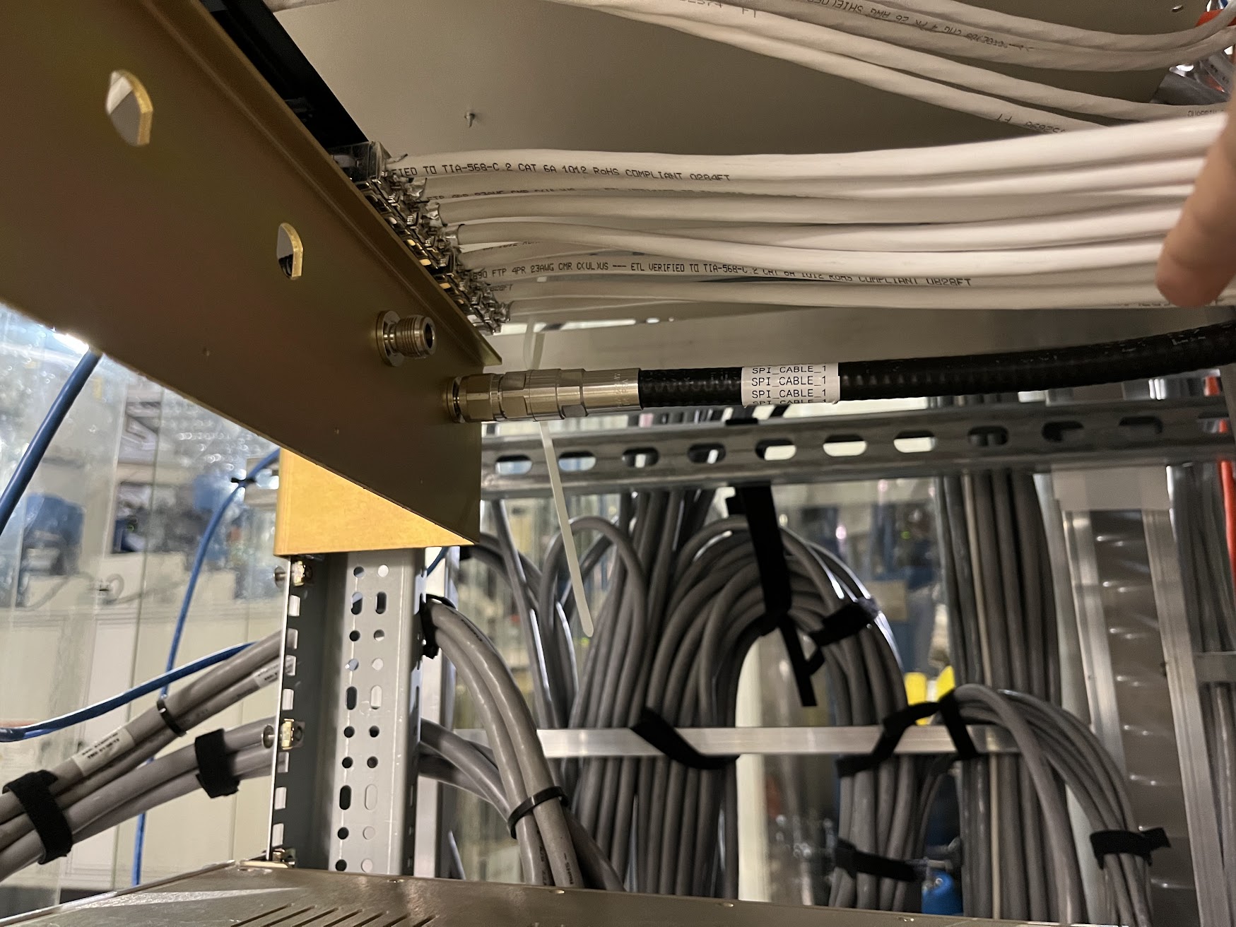
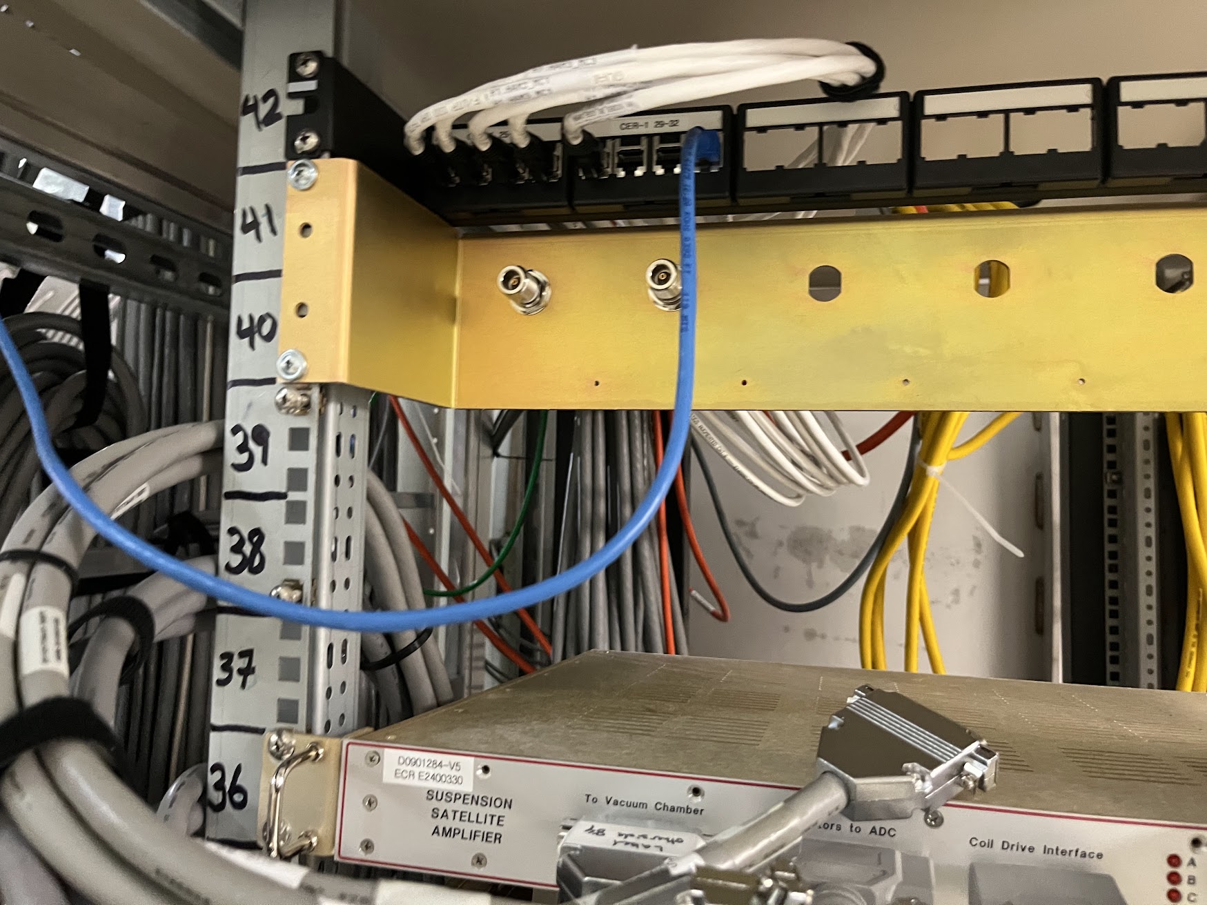
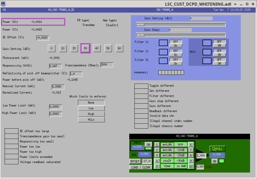
F. Clara, M. Pirello, J. Kissel
D2400111
G2401479

Fil and Marc have been doing the bulk of the work installing the diversity of cabling for SPI, as governed by D2400111 (and aided by slides in G2401479). What they started in LHO:89641 they've continued to the point of "we're as ready as we can be before we get the last of the electronics from the optics lab."

Here're some pictures of the status as of this afternoon. I'll attach them as comments to group them into a more digestible format.

A further step we can and will take in the coming days is to set up and power-budget the RF signal chain up to the point of the double mixer chassis, since this is not needed for the remaining optics-lab testing of the ISIK transceiver (which now must be redesigned; see E2600106).
Comments related to this report
Images attached to this comment


Images attached to this comment


Images attached to this comment

Images attached to this comment


Images attached to this comment


